


Model 76
Dehumidifier Control
Installation Instructions
READ AND SAVE THESE INSTRUCTIONS
The Model 76 is for use with any dehumidifier as an EXTERNAL CONTROL, including Aprilaire Models 1830, 1850 Series, and 1870 Series.
The Model 76 can also be used as a communicating REMOTE CONTROL with all Aprilaire Models 1830, 1850 Series, and 1870 Series.
(See OVERVIEW on page 3 for details.)
SAFETY INSTRUCTIONS
 WARNING
1.Improper installation may cause property damage or injury. Installation, service, and maintenance must be performed by a qualified service technician.
2.120 Volts may cause serious injury from electric shock. Disconnect electrical power before starting installation or servicing. Leave power disconnected until installation/service is completed. This control is not a 120 Volt (line voltage) device.
 CAUTION
1.Read all instructions before beginning installation.
2.Do not use in pool applications. Pool chemicals can damage the control.
3.Do not use solvents or cleaners on or near the display and circuit board. Chemicals can damage components.
1

TABLE OF CONTENTS |
|
|
OVERVIEW |
|
|
|
|
|
|
|
|
SAFETY INSTRUCTIONS . . . . . . . . . . . . . . . . . . . . . . . . . . . . . . . . . . . . . . . . . . . . . . |
. 1 |
. . . . . . . . . . |
The Aprilaire® Model 76 Dehumidifier Control provides control of the dehumidifier from the living. . . . . . . . . |
||
OVERVIEW |
3 |
|
space.. |
|
|
. . . . . . . . . . . |
. . . . . . |
|
|
||
SPECIFICATIONS |
3 |
|
The control can be installed as an EXTERNAL CONTROL, allowing the homeowner to set and |
||
|
adjust the humidity setting and turn dehumidification on or off from a convenient location.. In this |
||||
LOCATION RECOMMENDATIONS |
4 |
|
|||
. . . . . . . . . . |
application, the Model 76 uses an onboard sensor to monitor the relative humidity (%RH) in the. . . . . . |
||||
|
|
|
|||
INSTALLATION |
|
|
space in which it is located and displays the measured relative humidity on the digital display.. |
||
Mount Control . . . . . . . . . . . . . . . . . . . . . . . . . . . . . . . . . . . . . . . . . . . . . . . . . . . . . . . . . . . . . . . . . . . . . . . . . |
. 5 |
|
The control can also be installed to function as a REMOTE CONTROL if the dehumidifier is located |
||
Wiring |
|
|
|||
|
|
where it is not easy or convenient to access.. The control can be installed in any location within |
|||
. . . . . . . . . . . . . . . . . . . . . . . . . . . . . . . . . . . . . . . . . . . . . . . . . . . . . . . . External Control |
.7 |
. . . . . . . . . . . . |
the living space, with the dehumidifier installed in the area to be dehumidified, such as a crawl |
||
Remote Control |
9 |
|
|||
|
space, sealed attic, or basement.. The dryness level is set on the control and communicated to the |
||||
|
|
|
|||
SYSTEM CHECKOUT |
|
|
dehumidifier.. The dehumidifier communicates the measured relative humidity in the space being |
||
Power Up . . . . . . . . . . . . . . . . . . . . . . . . . . . . . . . . . . . . . . . . . . . . . . . . . . . . . . . . . . . . . . . . . . . . . . . . . . . . . |
.11 |
|
dehumidified back to the Model 76 Control where it is displayed on the digital display.. |
||
Test Mode . . . . . . . . . . . . . . . . . . . . . . . . . . . . . . . . . . . . . . . . . . . . . . . . . . . . . . . . . . . . . |
13. |
. . . . . . . . . . . |
. . . |
|
|
Humidity/Dryness Level Setting |
13 |
|
|
|
|
|
SPECIFICATIONS |
|
|
||
Offset . . . . . . . . . . . . . . . . . . . . . . . . . . . . . . . . . . . . . . . . . . . . . . . . . . . . . . . . . . . . . . . . . . . . . . . . . . . . |
.13. |
. . |
|
|
|
. . . . . . . . . . . . . . . . . . . . . . . . . . . . . . . . . . . . .Turning On and Setting the Control |
. .14 |
. . . . . . . . . . |
. . . . |
|
|
Sequence of Operation |
|
|
|
|
|
|
|
ELECTRICAL |
External |
Remote |
|
External Control |
15 |
|
|||
. . . . . . . . . . . |
|
|
|
||
|
|
Voltage: 24VAC +/-20% |
|
||
Remote Control . . . . . . . . . . . . . . . . . . . . . . . . . . . . . . . . . . . . . . . . . . . . . . . . . . . . . . . . . . . . . . . . . . . . . |
15 |
|
Input Voltage and Current |
Voltage: 9VDC (supplied by |
|
|
|
|
Current: 25mA (nominal), |
||
TROUBLESHOOTING |
|
|
dehumidifier control board) |
||
|
|
|
50mA (max..) at 24VAC |
||
Error Codes |
|
|
|
|
|
|
|
|
|
|
|
|
|
Output |
Dry Contact, Normally Open |
Communication |
|
External Control . . . . . . . . . . . . . . . . . . . . . . . . . . . . . . . . . . . . . . . . . . . . . . . . . . . . . . . . |
16. |
. . . . . . . . . . . |
|||
. . . . . . . . . . . . . . . . . . . . . . . . . . . . . . . . . . . . . . . . . . . . . . . . . . . . . . . . . . . . . . . . . . . . . Remote Control |
16 |
|
|
|
|
Table 2 – Error Codes |
17. |
|
|
|
|
|
CONTROL |
External |
Remote |
||
Table 3 – Troubleshooting Guide |
19 |
|
|||
|
|
|
|
||
|
Control Range |
40% – 80% RH |
1 (less dry) – 7 (more dry) |
||
|
|
|
|||
|
|
|
65°F – 42°F Dew Point |
||
|
|
|
|
|
|
|
|
|
|
|
|
|
|
|
Accuracy |
+/-5% RH |
See Dehumidifier Specifications |
|
|
|
|
|
|
|
|
|
Differential |
3% |
|
|
|
|
|
||
|
|
|
|
|
|
|
|
|
Low Limit |
40°F Dew Point |
50°F Dry Bulb |
|
|
|
|
|
|
|
|
|
High Limit |
99°F Dry Bulb |
105°F Dry Bulb |
|
|
|
|
|
|
2 |
3 |

LOCATION RECOMMENDATIONS
As a REMOTE CONTROL, the Model 76 can be mounted wherever is convenient for the homeowner..
Follow the recommendations below when installing the Model 76 as an EXTERNAL CONTROL..
MOUNT CONTROL
•In an area the homeowner wants to monitor and control moisture levels..
•On an interior wall..
•Approximately 5 feet off the floor..
•At least 18" from an outside wall..
DO NOT MOUNT CONTROL
•In the flow of a supply register.
•Behind doors, in corners or other dead air spaces..
•In direct sunlight, near lighting fixtures, or other appliances that give off heat..
•On an outside or unconditioned area wall..
•In stairwells or near outside doors..
•On a wall with concealed pipes or ductwork..
FIGURE 1 – MOUNTING LOCATION |
|
18" |
|
MINIMUM |
|
NO |
NO |
|
5 |
|
FEET |
NO |
|
|
90-1640 |
4 |
|
INSTALLATION
MOUNT CONTROL
FIGURE 2 – DISASSEMBLE CONTROL
APART
PULL
 BACK PLATE
 FRONT COVER
90-2486 |
FIGURE 3 – MOUNT BACK PLATE |
ANCHOR |
BACK PLATE |
SCREW |
90-2485 |
5 |
REQUIRED COMPONENTS
•18-24 gauge wire (field supplied) – 4 wires required, run new cable as needed..
•(2) #8 x 1-1/2" mounting screws (supplied)
•(2) Anchors (supplied)
1.Level the back plate on the wall and mark the mounting holes and wire access location on the wall..
2.Drill two 3/16" mounting holes and a 3/4" wire access hole.. See FIGURE 3..
3.Install the drywall anchors flush with the wall surface.. Note: Mounting holes on the back plate are designed to fit on a horizontal J-box..
4.Run a 4-wire cable from the dehumidifier to the wall mount location and through the square hole in the back plate..
5.Secure the back plate to the wall using the two #8 x 1-1/2" screws..
WIRING
WIRING MODEL 76 EXTERNAL CONTROL TO 1830 / 1850 SERIES / 1870 SERIES
1.Disconnect power to the dehumidifier and HVAC system.
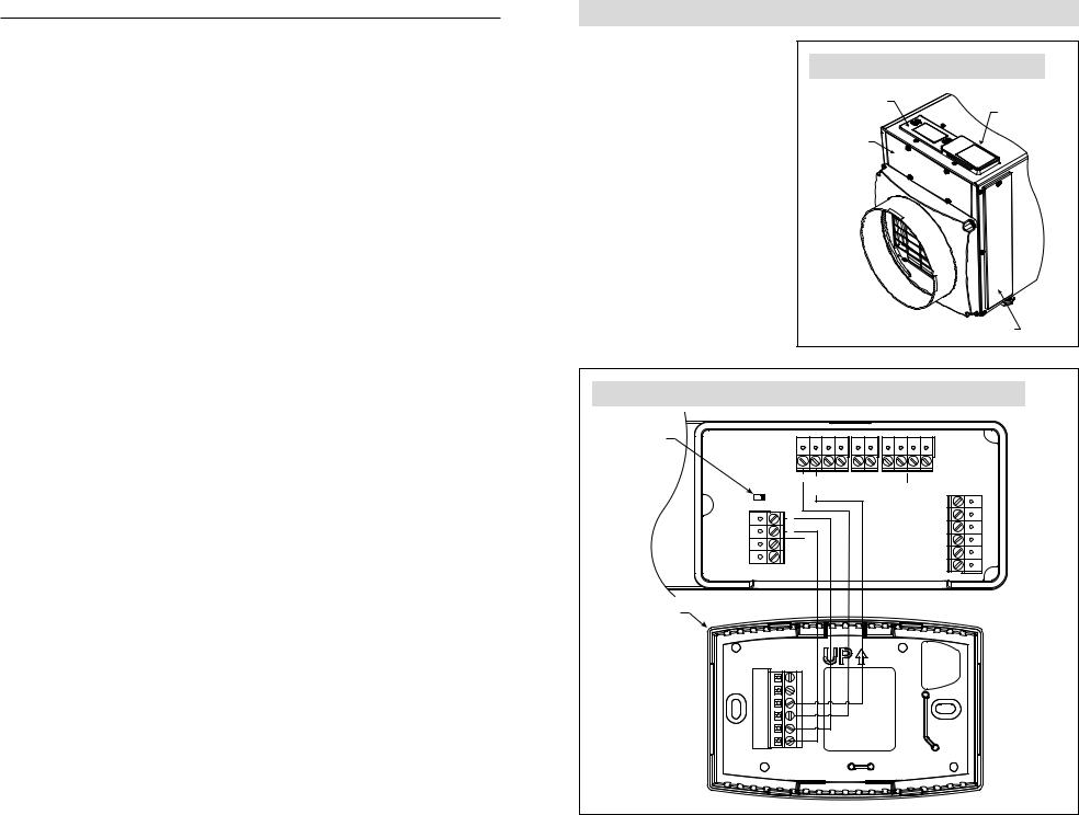
2.Remove the wiring access cover next to the control on the dehumidifier.. See FIGURE 4..
3.Wire the Model 76 to the dehumidifier as shown in FIGURE 5..
4.Ensure the NO/NC switch on the dehumidifier control is set to NO (see FIGURE 5)..
FIGURE 4 – WIRING ACCESS COVER LOCATION
CONTROL
WIRING ACCESS COVER
CONTROL PANEL COVER
FILTER ACCESS DOOR
90-1884
FIGURE 5 – WIRING MODEL 76 EXTERNAL CONTROL TO 1830 / 1850 SERIES / 1870 SERIES
NO/NC |
|
|
|
|
|
SWITCH |
|
|
|
|
|
+ |
- A |
B |
ODT |
VENT |
DEH |
|
Remote |
|
Sensor |
Dampers |
|
NC NO |
|
|
|
|
Gh |
|
|
|
|
Y W Gs Cf Rf .EQUIP HVAC |
|
FLOAT DH DH Switch |
|
|
|
|
|
MODEL 76 |
|
|
|
|
|
CONTROL |
|
|
|
|
|
A |
|
|
|
|
|
B |
|
|
|
|
|
C/- |
|
|
|
|
|
R/+ |
|
|
|
|
|
DH |
|
|
|
|
|
DH |
|
|
|
|
|
90-2489
6 |
7 |
 Loading...