


6404

Model 6404 & 6403 Zoned Comfort Control
®
Safety & Installation Instructions
READ AND SAVE THESE INSTRUCTIONS
61001165A 6403-6404 Zoned Comfort Control Install.indd 1 11/3/15 2:55 PM

SAFETY INSTRUCTIONS
Read this installation manual before beginning installation of the Aprilaire®
Zoned Comfort Control® system. For questions call Aprilaire customer
support at (800) 334-6011 or visit AprilairePartners.com.
WARNING
1. 120 Volts may cause serious injury from electrical shock. Leave
power disconnected until installation is complete.
2. The zone panel is designed for indoor use only. Do not expose
any of the components to moisture.
CAUTION
1. Turn o the system power before removing or installing any
wires into the terminals of any component on the system.
Wiring with a live circuit can lead to electrical shorts that can
damage components.
2. Installation must be done in accordance with all applicable
codes.
3. Installer should touch a grounded metal object before handling
the zone panel. This will prevent any static discharge that may
cause damage.
4. A zone panel may not control temperature properly unless the
heating and cooling system is properly sized and balanced.
5. Insucient air flow or excessive temperatures through the
heating and cooling system could result in equipment damage.
Refer to the manufacturer’s recommendations for minimum
safe airflow and temperature requirements.
6. Install an outdoor control to prevent non-seasonal equipment
starts if using auto changeover thermostats.
7. Do not mount the zone panel on any exterior wall or equipment
supply ductwork.
8. Do not install the zone panel where temperatures exceed 158°F
(70°C) or are below 32°F (0°C), non-condensing.
9. Improper system installation could cause water damage from
frozen pipes. Check system operation after installation.
TABLE OF CONTENTS
SAFETY INSTRUCTIONS . . . . . . . . . . . . . . . . . . . . . . . . . . . . . . . . . . . . . . . . . . 2
SPECIFICATIONS . . . . . . . . . . . . . . . . . . . . . . . . . . . . . . . . . . . . . . . . . . . . . . . . . 3
APPLICATION & ACCESSORIES . . . . . . . . . . . . . . . . . . . . . . . . . . . . . . . . . . . . 3
ZONE PANEL LAYOUT . . . . . . . . . . . . . . . . . . . . . . . . . . . . . . . . . . . . . . . . . . . . 4
INSTALLATION . . . . . . . . . . . . . . . . . . . . . . . . . . . . . . . . . . . . . . . . . . . . . . . . . . . 5
Mounting . . . . . . . . . . . . . . . . . . . . . . . . . . . . . . . . . . . . . . . . . . . . . . . . . . . . . . 5
Installation Location Recommendations . . . . . . . . . . . . . . . . . . . . . . . . . . 5
WIRING . . . . . . . . . . . . . . . . . . . . . . . . . . . . . . . . . . . . . . . . . . . . . . . . . . . . . . . . . 6
Select and Wire the Transformer to the Control Panel. . . . . . . . . . . . . . 6
Zone Damper Wiring . . . . . . . . . . . . . . . . . . . . . . . . . . . . . . . . . . . . . . . . . . . 7
Discharge Air Temperature Sensor (Included) . . . . . . . . . . . . . . . . . . . . . 8
Outdoor Temperature Sensor (Optional) . . . . . . . . . . . . . . . . . . . . . . . . . . 8
Wireless Outdoor Temperature Sensor (Optional). . . . . . . . . . . . . . . . . . 8
Expansion Panels (Optional – Model 6404 Only) . . . . . . . . . . . . . . . . . . 9
Thermostat Terminal Definitions . . . . . . . . . . . . . . . . . . . . . . . . . . . . . . . . 10
HVAC Terminal Definitions. . . . . . . . . . . . . . . . . . . . . . . . . . . . . . . . . . . . . . 10
Two-Stage Furnace and A/C. . . . . . . . . . . . . . . . . . . . . . . . . . . . . . . . . . . . . 11
Two-Stage Heat Pump . . . . . . . . . . . . . . . . . . . . . . . . . . . . . . . . . . . . . . . . . .11
Boiler and A/C . . . . . . . . . . . . . . . . . . . . . . . . . . . . . . . . . . . . . . . . . . . . . . . . . 11
Radiant Floor First-Stage Heat,
Furnace Second-Stage Heat and A/C. . . . . . . . . . . . . . . . . . . . . . . . . . . 11
INSTALLER SETUP. . . . . . . . . . . . . . . . . . . . . . . . . . . . . . . . . . . . . . . . . . . . . . . 12
How to Configure. . . . . . . . . . . . . . . . . . . . . . . . . . . . . . . . . . . . . . . . . . . . . . 12
LCD Installer Screen Settings & Descriptions. . . . . . . . . . . . . . . . . . . . . . 13
Sequence of Operation. . . . . . . . . . . . . . . . . . . . . . . . . . . . . . . . . . . . . . . . . 14
LCD Home Screen Display & Descriptions . . . . . . . . . . . . . . . . . . . . . . . . 16
INSTALLER CHECKOUT . . . . . . . . . . . . . . . . . . . . . . . . . . . . . . . . . . . . . . . . . . 17
LIMITED WARRANTY . . . . . . . . . . . . . . . . . . . . . . . . . . . . . . . . . . . . . . . . . . . . 18
2 English
61001165A 6403-6404 Zoned Comfort Control Install.indd 2 11/3/15 2:55 PM
SPECIFICATIONS
INPUT RATINGS
Voltage: 18-30VAC 50/60 Hz
MAXIMUM CURRENT
Damper output per zone (fused): 18VA at 158°F, 30VA at 90°F
Zone panel and thermostats (fused): 18VA at 158°F, 30VA at 90°F
Zone panel consumption: 4VA max
Note: Use 18 or 20 AWG solid (non-stranded) wire
ENVIRONMENT
Temperature (operating): 32°F – 158°F
Temperature (shipping): -40°F – 165°F
Humidity: 5% – 90%, non-condensing
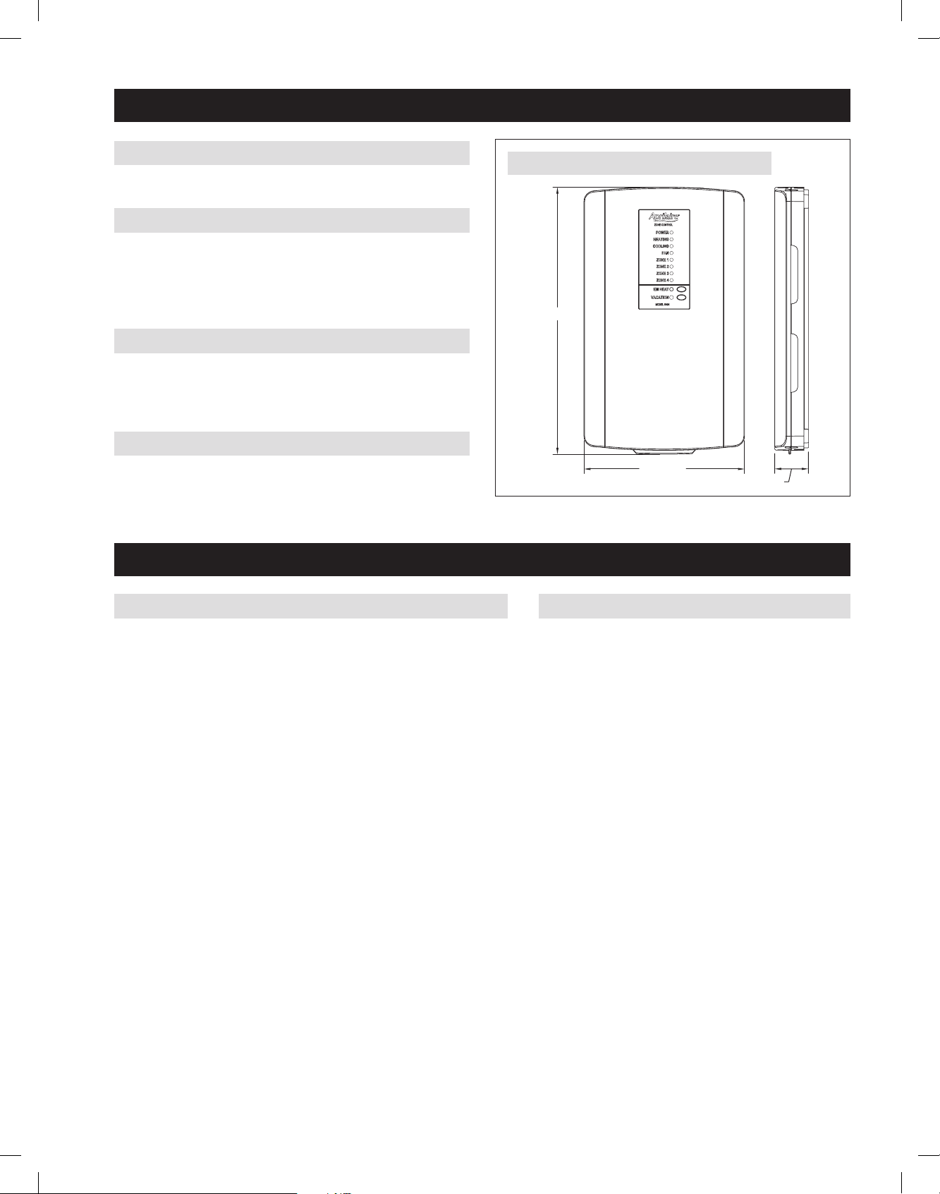
DIMENSIONS
See FIGURE 1.
8.85 (225)
1.86 (47)
14.72 (374)
90-2071
FIGURE 1 – ZONE PANEL DIMENSIONS IN INCHES (mm)
APPLICATION & ACCESSORIES
APPLICATION
The Model 6404 or 6403 Zone Panel can be configured to control heat pump
or conventional applications. The Model 6403 can control up to 3 zones. The
6404 can control up to 4 zones and is expandable up to 12 with the use of
the Model 6401 two-zone expansion panel. The features include:
• 2 heating and two 2 cooling stages (conventional)
• 4 heating and 2 cooling stages (heat pump)
• Integrated balance point control
• Equipment protection
ACCESSORIES
• Discharge Air Temperature Sensor (DAT):
Model 8052 (included)
• Outdoor Temperature Sensor (ODT):
Model 8052 (optional)
• Wireless Outdoor Temperature and Humidity Sensor:
Model 8056 (optional)
• Two Zone Expansion Panel:
Model 6401 (optional)
English 3
61001165A 6403-6404 Zoned Comfort Control Install.indd 3 11/3/15 2:55 PM
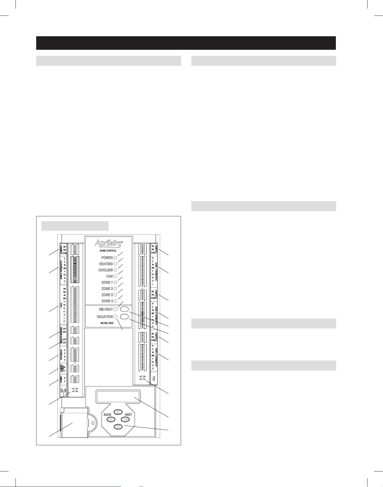
ZONE PANEL LAYOUT
TERMINALS
1. HVAC – HVAC connection
2. ZONE 1 THERMOSTAT – Thermostat connection
3. ZONE 2 THERMOSTAT – Thermostat connection
4. ZONE 3 THERMOSTAT – Thermostat connection
5. ZONE 4 THERMOSTAT (6404 only) – Thermostat connection
6. DAMPER 1 – Zone 1 damper connection
7. DAMPER 2 – Zone 2 damper connection
8. DAMPER 3 – Zone 3 damper connection
9. DAMPER 4 (6404 only) – Zone 4 damper connection
10. REMOTE SENSORS DAT (Discharge Air Temperature)
11. REMOTE SENSORS ODT (Outdoor Air Temperature)
12. EXPANSION (6404 only) – Expansion port (Model 6401)
13. DAMPER POWER – Damper power (dedicated 24VAC)
14. POWER – Zone panel and thermostat power (dedicated 24VAC)
LEDs
15. POWER – Green: 24VAC is present. Flashing: TDO button is pressed.
16. HEATING – Green: Heating is active. Flashing: DAT high temperature
limit reached.
17. COOLING – Green: Cooling is active. Flashing: DAT low temperature
limit reached.
18. FAN – Green: Fan output is active.
19. ZONE 1 – Green: Damper is open. Red: Damper is closed.
20. ZONE 2 – Green: Damper is open. Red: Damper is closed.
21. ZONE 3 – Green: Damper is open. Red: Damper is closed.
22. ZONE 4 – Green: Damper is open. Red: Damper is closed.
23. EM HEAT – Amber: Emergency Heat mode is enabled using the
EM Heat button or an Emergency Heat call is active based on a
thermostat Emergency Heat call.
24. VACATION – Green: Vacation mode is enabled.
BUTTONS
25. EM HEAT – Used to enable/disable Emergency Heat mode. In
Emergency Heat mode the compressor will be locked out and only
auxiliary heat will be used to satisfy heating calls. Note: The EM
Heat button does not function when the zone panel is configured to
control conventional equipment.
26. VACATION – Used to enable/disable Vacation mode. In Vacation
mode all zones will be controlled by the thermostat in Zone 1.
27. Navigation buttons – Used for installer setup and checkout.
28. TDO (Time Delay Override) – Accelerates timing (6 seconds = 1
minute). Used to speed up minimum on and off timers.
29. Wireless Outdoor Sensor Connect – Used to link an optional outdoor
temperature sensor to the zone panel.
LCD
30. In normal operation, displays zone panel status. In installer setup,
used to configure the zone panel. In installer checkout, used to step
through the installer test.
WIRELESS OUTDOOR SENSOR
31. Placement of optional Model 8056 wireless outdoor radio module.
15
26
25
8
7
6
9
27
28
11
10
5
29
1
12
13
14
31
2
16
17
18
19
20
21
22
24
3
4
23
30
90-2084
FIGURE 2 – ZONE PANEL LAYOUT
4 English
61001165A 6403-6404 Zoned Comfort Control Install.indd 4 11/3/15 2:55 PM
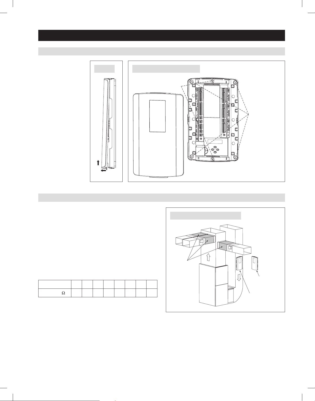
USE TWO SCREWS WHEN
ATTACHING TO A WALL STUD
USE FOUR SCREWS
WHEN ATTACHING TO
DRYWALL/PLASTER
LOCATE DAT
SENSOR IN
SHADED AREA.
(SUPPLY DUCT)
ZONE CONTROL
MOUNTED ON
WALL OR STUD
ZONE CONTROL
MOUNTED ON
RETURN DUCT
1
2
90-2072
90-2089
90-2107
FIGURE 4 – MOUNTING HOLE LOCATIONS
FIGURE 5 – LOCATION RECOMMENDATIONS
FIGURE 3
INSTALLATION
MOUNTING
1. Separate the zone
panel cover from the
base. See FIGURE 3.
2. Use the base as a
template to drill
mounting holes.
See FIGURE 4 for
mounting hole
locations.
3. Attach the base to an
interior wall, stud or
return duct.
INSTALLATION LOCATION RECOMMENDATIONS
1. Mount the zone panel near the HVAC equipment. Locate the panel
on an interior wall, stud or return duct. See FIGURE 5.
2. Locate the Discharge Air Temperature (DAT) in the supply trunk,
downstream of the heat exchanger and cooling coils, and before the
zone dampers (refer to the shaded areas of FIGURE 5). Note: Do
not mount the sensor in direct line-of-sight of the heat exchanger,
cooling coils or UV lights as this may cause the sensor to report false
temperature readings. Do not route wires along 120VAC lines.
3. Before wiring the sensor to the control panel, measure the resistance
across the sensor. The resistance corresponds (approximately) to the
sensed temperature according to the following table:
Temperature (°F) 30 40 50 60 70 80 90 100
Resistance (k ) 34.6 26.1 19.9 15.3 11.9 9.4 7.4 5.9
English 5
61001165A 6403-6404 Zoned Comfort Control Install.indd 5 11/3/15 2:55 PM
WIRING
WARNING
120 volts may cause serious injury from electrical shock. Sudden operation
may cause serious injury from moving parts. Leave power disconnected
until installation is complete.
Follow these steps for all system connections. Wiring will vary depending on
equipment.
See page 11 for complete wiring diagram examples.
Wiring of the zone panel must comply with applicable codes, ordinances and
regulations.
• Use only 18 or 20 gauge solid (non-stranded) wire.
• Strip off 7/16" of insulation from the wire.
• Push wire into the terminal of the zone panel.
• To release the wire, press down on the top of the terminal and pull the wire out.
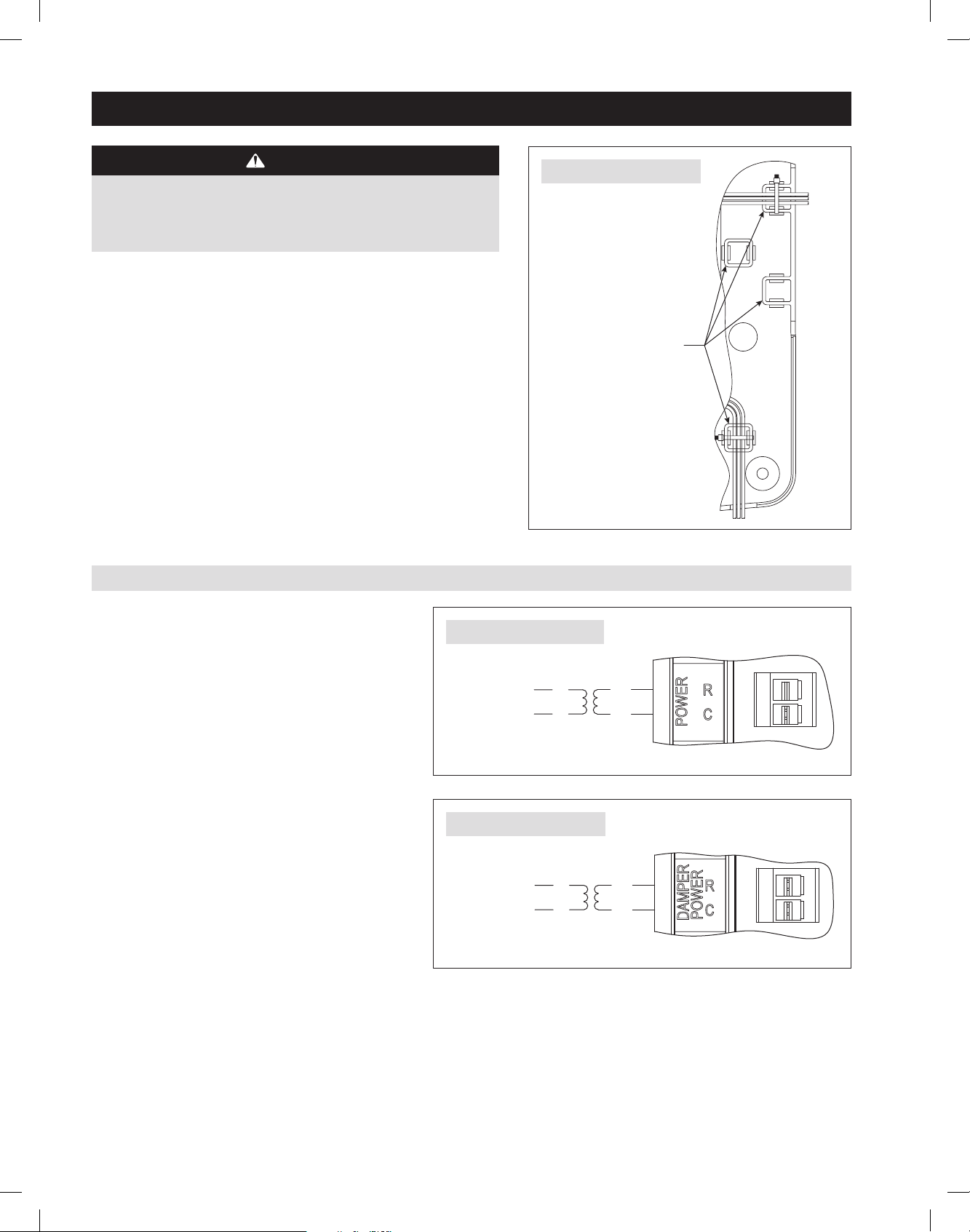
• The zone panel supports multiple options to route and anchor wires to the
housing. See FIGURE 6.
WIRE TIE MOUNTS
TRANSFORMER #1
DEDICATED
24 VAC
120 VAC
24 VAC
120 VAC
TRANSFORMER #2
DEDICATED
90-2073
90-2092
90-2093
FIGURE 6 – WIRE TIE MOUNTS
FIGURE 7 – TRANSFORMER #1
FIGURE 8 – TRANSFORMER #2
SELECT AND WIRE THE TRANSFORMER TO THE CONTROL PANEL
1. Two separate 24-volt transformers are required for the
system. The HVAC Equipment transformer cannot be used
for power. Transformer #1 is used to power the zone panel
and thermostats. Transformer #2 is used to power the
zone dampers.
2. Wire 24VAC from Transformer #1 to the POWER, R & C
terminals (see FIGURE 7) .
3. Wire 24VAC from Transformer #2 to the DAMPER POWER,
R & C terminals (see FIGURE 8).
4. Sizing Transformer #2:
a. Add up all the zone dampers that are in the system.
b. Subtract the number of dampers in the zone with the
least number of dampers.
c. This is the most number of dampers that could be
energized at one time. Multiply this number by 10 to
determine the transformer size.
Example: If you have a 4-zone system, and there
are two dampers per zone, then the total number of
dampers that could be energized at one time is,
8 - 2 = 6 dampers
6 dampers x 10VA per damper = 60VA required
d. Select a transformer that meets or exceeds the value
calculated.
6 English
61001165A 6403-6404 Zoned Comfort Control Install.indd 6 11/3/15 2:55 PM
 Loading...