


Aprilaire 8365, 8366, 8344, 8346, 8348 User Manual
...Electronic
Thermostats
MODEL 8344 HEAT/COOL NON-PROGRAMMABLE
MODEL 8346 HEAT PUMP NON-PROGRAMMABLE
MODEL 8348 HEAT/COOL MULTI-STAGE NON-PROGRAMMABLE MODEL 8363 HEAT/COOL 5/2 DAY PROGRAMMABLE MODEL 8365 HEAT PUMP 5/2 DAY PROGRAMMABLE
MODEL 8366 HEAT/COOL MULTI-STAGE 5/2 DAY PROGRAMMABLE
Installation Manual
WARNINGS
120 volts may cause serious injury from electrical shock. Disconnect electrical power to the furnace & air conditioner before starting installation. This thermostat is not a 120 volt (line voltage) device.
Improper installation may cause serious injury from electrical shock. This product must be installed by a qualified heating & air conditioning contractor in accordance with NEC Standards and applicable local and state codes.
Mercury is toxic and may be hazardous to your health. Any replaced thermostats containing mercury must be disposed of properly. Contact local authorities for disposal information.
SPECIFICATIONS
Comfort Range |
60°F – 80°F |
Comfort Control Accuracy |
± 1°F (applies to settings within Comfort Range) |
|
|
Operating Range1 |
32°F – 99°F |
Maximum Control Accuracy |
± 2°F |
|
|
Temperature Setting (Control) Range |
50°F – 90°F heating; 60°F – 90°F cooling |
|
|
Switched Load Voltage |
18 – 30 volts |
|
|
Maximum Operating Current |
1.0 Amp |
|
|
Maximum Surge Current |
3.0 Amps |
|
|
Low Limit Temperature2 |
41°F ± 9°F |
High Limit Temperature3 |
100°F ± 9°F |
1Operating Range is the temperature range in which the thermostat will accurately display temperature.
2Low Limit Temperature is the temperature setting of an internal, temperature-controlled mechanical switch in a circuit between RH and W for Models 8344, 8348, 8363 and 8366, and between R and W2 for Models 8346 and 8365. This device is intended to prevent freezing of water pipes should battery replacement be neglected.
3High Limit Temperature is the setting of an internal, temperature-controlled mechanical switch in the circuit between the RH and the W terminal (W and W2 terminals for Model 8348 and 8366). This device will limit the room temperature should the contacts of the
heat relay remain closed. Applies to Models 8344, 8348, 8363 and 8366 only.
1
THERMOSTAT INSTALLATION INSTRUCTIONS
Step1. Choose a location to mount the thermostat
•Approximately 5 feet off the floor (refer to local codes for compliance with the Americans with Disabilities Act).
•On an interior wall where the temperature is most representative of the zone being controlled by the thermostat.
•At least 18 inches away from an outside wall.
DO NOT MOUNT THERMOSTAT…
• Behind doors, in corners or other dead air spaces.
•In direct sunlight, near lamps or other sources of heat.
•On an outside wall or any wall exposed to an unconditioned space (i.e. garage).
•In the airflow path of a supply register or near outside doors.
•On a wall where concealed pipes or ductwork will affect the thermostat temperature accuracy.
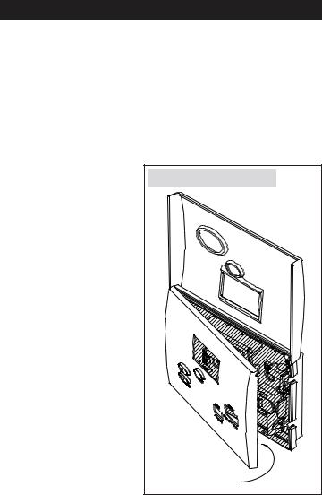
Step 2. Disassemble
the thermostat
•Flip open the cover.
•Remove the face of the thermostat – no tools required.
Disassemble the Thermostat |
Pull Here to Open |
2 |
Step 3. Mount the thermostat on the wall
There are two sets of mounting holes – one set for use when mounting to a junction box, another set for direct wall mounting.
IMPORTANT! TURN OFF POWER AT THE HVAC EQUIPMENT BEFORE PROCEEDING WITH THERMOSTAT INSTALLATION!
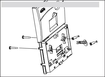
Mounting the thermostat directly to the wall (without junction box)
1.Place the thermostat wire opening over the wall opening. If replacing a thermostat, place the thermostat to cover the old thermostat silhouette. The base of the thermostat is raised to allow for wire routing behind the thermostat.
2.Level the thermostat (for appearance only) and mark the mounting hole locations.
3.Drill a 3/16” dia. hole at the marked locations and install drywall anchors (included). Drywall anchors should be used unless installing on paneling or other hard surfaces. Anchors should be flush with the wall surface.
4.Secure the thermostat to the wall using two (2), #8 x 1-1/2” long pan head screws (included).
Mounting the Thermostat Directly to the Wall (without Junction Box)
3

Mounting the thermostat to a junction box
1.Install the top j-box screw (not included), until the head is approximately 1/8” from the surface of the wall.
2.Slide the thermostat on to the top screw.
3.Install the bottom screw (not included) to finish the installation.
Mounting the Thermostat to a Junction Box
Step 4. Set the ELEC/GAS switch to the proper position (Models 8344, 8348,
8363 and 8366 only)
Setting the switch to ELEC will cause the
G terminal to energize with the W terminal
on a call for heat. GAS Only the W terminal
will energize on a heat call in the GAS position.
4
 Loading...