


Model 8620W Universal Touch Screen
Wi-Fi Thermostat with Integrated
Indoor Air Quality Solutions
Safety &
Installation
Instructions
READ AND SAVE THESE INSTRUCTIONS
TABLE OF CONTENTS
WI-FI SETUP |
|
|
SETUP & TESTING |
|
Wi-Fi Setup . . . . . . . . . . . . . . . . . . . . . . . . . . |
2. |
. . . . |
Equipment. . . type selection switch (SW1) . . . . . . . . |
. . . . 7 |
|
|
|
Installer setup menu . . . . . . . . . . . . . . . . . . |
. . . 7. . . . . . |
INSTALLATION |
|
|
Change system settings . . . . . . . . . . . . . . . . . . . . . |
. . . . 7 |
Installation location recommendations |
2 |
|
. . . . . . . . .HVAC installer system settings table |
. . 8. -9 |
|
Indoor Air Quality system settings tables |
10-12 |
||
Outdoor temperature sensor (included) |
2 |
|
||
|
Air cleaning sytem settings table |
10 |
||
Remote temperature sensor (optional) |
3. |
|
||
|
Humidifier system settings table |
10-11 |
||
Thermostat mounting |
3 |
|
||
|
Dehumidifier system settings table |
11 |
||
Power & reset options |
4 |
|
||
|
Ventilation system settings table |
12 |
||
Wiring terminal |
4 |
|
||
. . . . |
Removal of Indoor Air Quality control buttons |
13 |
||
|
|
|
||
|
|
|
System test menu |
13-14 |
WIRING DIAGRAMS |
|
|
||
Conventional heat/cool single transformer |
5 |
|
. . . . . . . . . . . . . . . . . . . . . . . . .System test tables |
15-16 |
|
|
|
||
Conventional heat/cool two transformer |
5 |
|
|
|
. . |
REFERENCES |
|
||
Heat pump single transformer |
5 |
|
|
|
|
Quick reference to controls & display |
17 |
||
Heat pump two transformer |
5 |
|
||
. . . |
Troubleshooting. |
18. |
||
Indoor Air Quality equipment – dehumidifier .. .. .. .. .. .. .. .. |
6 |
|
||
Indoor Air Quality equipment – humidifier .. .. .. .. .. .. .. .. .. .. |
6 |
|
. . . . . . . . . . . . . . . . . . . . . . . . . . . . . . .Error codes |
. . . 19 |
Indoor Air Quality equipment – ventilation |
6 |
|
. . . . . . . . . . . . . . . .Thermostat features |
. . . . . . . . .19 |
|
Specifications |
20 |
||
|
|
|

WI-FI SETUP
For detailed instructions for connecting the thermostat to a Wi-Fi network and registering it to an Aprilaire account, refer to the Wi-Fi Quick Start Guide included in the box..
INSTALLATION
INSTALLATION LOCATION RECOMMENDATIONS
Thermostat should be mounted:
•On an interior wall, in a frequently occupied space..
•Approximately 5‘ above floor..
•At least 18” from outside wall..
•Thermostat can be mounted to a vertical junction box..
OUTDOOR TEMPERATURE SENSOR (INCLUDED)
Do not mount thermostat:
•Behind doors, in corners or other dead air spaces..
•In direct sunlight, near lighting fixtures, or other appliances that give off heat..
•On an outside or unconditioned area wall..
•In the flow of a supply register, in stairwells, or near outside doors..
•On a wall with concealed pipes or ductwork..
Outdoor temperature can be measured by attaching the included 8052 sensor to the S1 and S2 terminals.. The outdoor sensor must be enabled in the installer setup menu..
Heat pump models can use the outdoor temperature to effectively utilize the heat pump:
•When the outdoor temperature is less than the Low Balance Point, the heat pump will be locked out and only auxiliary heating will be used to provide heating..
•When the outdoor temperature is higher than the High Balance Point, the auxiliary heating will be locked out and only the heat pump will be used to provide heating..
Indoor Air Quality functions can use the outdoor temperature sensor to:
•Control humidification setpoint based on outdoor temperature to prevent condensation
•Lock out humidification for temperatures over 60°F or below -30°F..
•Lock out ventilation based on high and/or low outdoor temperatures..
•Display outdoor temperature on thermostat..
Outdoor temperature sensor should be mounted:
•On side of building out of direct sunlight (north side recommended)..
•Above snow line..
•At least 3’ away from exhaust vents and condensing lines..
•Using less than 300’ of wire..
•Do not route wires along 120 VAC lines..
I2 |
C |
I1 O/B Y Y2 G RC R W2 W |
L S2 S1 T1 T2 |
INSTALLATION
REMOTE TEMPERATURE SENSOR (OPTIONAL)
A remote temperature sensor can be used for control if the thermostat is to be mounted in a concealed location or a remote sensor can be averaged with the thermostat sensor to control a large space.. An 8051 flush mount or 8053 surface mount remote temperature sensor can be attached to the T1 and T2 terminals and mounted in a
recommended area.. The remote sensor must be enabled in the installer set-up menu, and once enabled will override or be averaged with the thermostat’s internal temperature sensor, based on the setting..
Remote temperature sensor should be mounted:
•On an interior wall, in a frequently occupied space..
•Approximately 5‘ above floor..
•At least 18” from outside wall..
•Using less than 300’ of wire..
Do not mount remote sensor:
•Behind doors, in corners or other dead air spaces..
•In direct sunlight, near lighting fixtures, or other appliances that give off heat..
•On an outside or unconditioned area wall..
•In the flow of a supply register, in stairwells, or near outside doors..
•On a wall with concealed pipes or ductwork..
•Near 120 VAC lines..
I2 |
C |
I1 O/B Y Y2 G RC R W2 W |
L S2 S1 T1 T2 |
THERMOSTAT MOUNTING
1..Remove the rear mounting plate from the thermostat..
2..Pull wires through the opening on the back of the rear mounting plate..
3..Position and level the mounting plate of the thermostat on wall and mark the hole locations with a pencil..
4..Drill 1/4” holes and insert supplied anchors (drywall only)..
5..Place mounting plate over anchors, insert and tighten screws..
6..Seal wire entry holes to prevent drafts affecting temperature readings..
2 |
3 |

INSTALLATION
POWER & RESET OPTIONS
The thermostat is powered from 24VAC.. In the case of
power loss the thermostat will maintain the clock for 24
hours.. The thermostat has a memory backup that saves RESET BUTTON
the thermostat settings in case of power interruption..
The reset button located under the cover on the front of the thermostat can be used to reset the thermostat to factory defaults.. The system settings will also be set to default..
90-2012
WIRING TERMINAL
I2 C I1 O/B Y Y2 G RC R W2 W L S2 S1 T1 T2
Wire specifications:
18-24 gauge thermostat wire
Installation notes:
•Ensure power at the HVAC equipment is off..
•Loosen screw terminals, insert stripped wire and re-tighten..
•Push the excess wire back into the opening and plug the wall opening to prevent drafts..
I1 & I2 – Indoor Air Quality control output C – Common
O/B – Reversing valve
Y – First stage cooling (conventional) / First stage compressor (heat pump)
Y2 – Second stage cooling (conventional) / Second stage compressor (heat pump) G – Fan
RC – 24VAC supply cooling1 R – 24VAC supply heating1
W2 – Second stage heat (conventional) / Second stage auxiliary (heat pump) W – First stage heat (conventional) / First stage auxiliary (heat pump)
L – System fault indicator (optional) (heat pump only) S1 & S2 – outdoor temperature sensor (included) T1 & T2 – remote temperature sensor (optional)
1Jumper between RC & R is used in single transformer systems (see wiring diagrams).
INSTALLATION
CONVENTIONAL HEAT/COOL WIRING DIAGRAMS
SINGLE TRANSFORMER (USE JUMPER WIRE) |
|
TWO TRANSFORMERS (REMOVE JUMPER WIRE) |
||||||||||||||||
|
|
|
|
TRANSFORMER |
|
|
OUTDOOR TEMP SENSOR |
|
|
|
|
|
|
COOLING TRANSFORMER |
HEATING TRANSFORMER |
|
OUTDOOR TEMP SENSOR |
|
|
|
USED 1st COOLING |
2nd COOLING FAN |
JUMPER |
2nd HEATING 1st HEATING |
USED |
REMOTE TEMP |
SENSOR |
|
|
USED 1st COOLING |
2nd COOLING FAN |
2nd HEATING 1st HEATING |
USED |
REMOTE TEMP SENSOR |
|||
|
|
NOT |
|
|
|
NOT |
|
|
|
|
|
NOT |
|
|
|
NOT |
|
|
I2 |
C |
I1 O/B Y |
Y2 G RC R W2 W |
L |
S2 S1 T1 T2 |
I2 |
C |
I1 O/B Y |
Y2 G RC R W2 W |
L |
S2 S1 T1 T2 |
|||||||
HEAT PUMP WIRING DIAGRAMS |
|
|
|
|
|
|
|
|
|
|
|
|
|
|||||
SINGLE TRANSFORMER (USE JUMPER WIRE) |
|
TWO TRANSFORMERS (REMOVE JUMPER WIRE) |
||||||||||||||||
|
|
|
|
|
|
|
|
|
|
|
|
|
|
|
HEATING TRANSFORMER |
|
|
|
|
|
REVERSING VALVE 1st COMPRESSOR |
2nd COMPRESSOR FAN |
HEAT PUMP TRANSFORMER |
2nd AUX HEATING 1st AUX HEATING |
|
OUTDOOR TEMP SENSOR |
REMOTE TEMP |
|
|
|
REVERSING VALVE 1st COMPRESSOR |
2nd COMPRESSOR FAN |
HEAT PUMP TRANSFORMER |
2nd AUX HEATING 1st AUX HEATING |
|
OUTDOOR TEMP SENSOR |
REMOTE TEMP SENSOR |
|
|
JUMPER |
FAULT DETECT |
SENSOR |
|
|
FAULT DETECT |
|||||||||||
I2 |
C |
I1 O/B Y |
Y2 G RC R W2 W |
L |
S2 S1 T1 T2 |
I2 |
C |
I1 O/B Y |
Y2 G RC R W2 W |
L |
S2 S1 T1 T2 |
|||||||
4 |
5 |
INSTALLATION
INDOOR AIR QUALITY EQUIPMENT WIRING DIAGRAMS
DEHUMIDIFIER WIRING |
HUMIDIFIER WIRING |
|
TRANSFORMER |
DEHUMIDIFIER |
HUMIDIFIER |
I2 C I1 O/B Y Y2 G RC R W2 W L S2 S1 T1 T2 I2 C I1 O/B Y Y2 G RC R W2 W L S2 S1 T1 T2
VENTILATION WIRING


 TRANSFORMER
NORMALLY CLOSED DAMPER
I2 C I1 O/B Y Y2 G RC R W2 W L S2 S1 T1 T2
Note: The I1/I2 output is a dry contact closure.. The humidifier wiring diagram assumes the control is powering a solenoid valve.. The dehumidifier wiring diagram is for a normally open dry contact input.. The ventilation diagram assumes the control is for a normally closed damper.. Refer to the individual humidifier, dehumidifier or ventilation installation instructions for product specific wiring details..
SETUP & TESTING
EQUIPMENT TYPE SELECTION SWITCH (SW1)
This thermostat has the option of being used in heat |
|
|
pump or heat/cool systems.. Switch SW1 located on the |
HC |
SW1 |
back of the thermostat’s face is used to select this option.. |
HP |
HEAT/COOL |
This setting is displayed in the Installer System Settings |
|
HEAT PUMP |
|
|
|
under Equipment Type.. |
|
|
Note: Thermostat reboots within 10 seconds after switch |
|
|
position is changed.. |
|
HC |
|
HP |
|
|
|
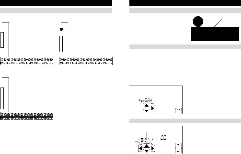
INSTALLER SETUP MENU
HOW TO ENTER THE INSTALLER SETUP MENU AND SELECT EQUIPMENT TO SETUP:
In the Installer Setup, HVAC or Indoor Air Quality setup can be selected.. If Indoor Air Quality setup is selected, the user can then select to set up Air Cleaning, Humidification, Dehumidification or Ventilation..
Press [MODE] to set system to OFF.. Press [MENU] to enter main menu..
Press and hold [SETUP] for seven seconds, [INSTALL SETUP] appears..
Press [INSTALL SETUP] to enter installer setup menu..
Press  or
or  to adjust the option..
Press [MENU] to exit..
Press [NEXT] to select option..
If Indoor Air Quality was selected, Press  or
or  to adjust the Outdoor Sensor setting or Indoor Air Quality option..
Press [NEXT] to select Outdoor Sensor setting or Indoor Air Quality option..
System Settings can now be changed..
CHANGE SYSTEM SETTINGS
SETTING SETTING
DESCRIPTION NUMBER
SETTING
OPTIONS
Press [NEXT] or [BACK] to page through the settings.. Press  or
or  to adjust the setting..
Press [DONE] to save and exit, or [CANCEL] to exit without saving..
The thermostat will discard changes and exit if nothing is pressed within 60 seconds..
To reset the installer settings to the default, reset the thermostat by pressing the [RESET] button for 5 seconds..
Note: The reset button is disabled when the thermostat is removed from the wall for programming..
6 |
7 |
 Loading...