


6303
READ AND SAVE THESE INSTRUCTIONS
Model 6303 & 6302
Zoned Comfort Control
®
Safety & Installation Instructions
61001212 B2206667E 2.19
English 1

SAFETY INSTRUCTIONS
Read this installation manual before beginning installation of the Aprilaire®
Zoned Comfort Control® system. For questions call Aprilaire customer
support at (800) 334-6011 or visit AprilairePartners.com.
WARNING
1. 120 Volts may cause serious injury from electrical shock. Leave
power disconnected until installation is complete.
2. The zone panel is designed for indoor use only. Do not expose
any of the components to moisture.
CAUTION
1. Turn o the system power before removing or installing any
wires into the terminals of any component on the system.
Wiring with a live circuit can lead to electrical shorts that can
damage components.
2. Installation must be done in accordance with all applicable
codes.
3. Installer should touch a grounded metal object before handling
the zone panel. This will prevent any static discharge that may
cause damage.
4. A zone panel may not control temperature properly unless the
heating and cooling system is properly sized and balanced.
5. Insucient air flow or excessive temperatures through the
heating and cooling system could result in equipment damage.
Refer to the manufacturer’s recommendations for minimum
safe airflow and temperature requirements.
6. Do not mount the zone panel on any exterior wall or equipment
supply ductwork.
7. Do not install the zone panel where temperatures exceed 158°F
(70°C) or are below 32°F (0°C), non-condensing.
8. Improper system installation could cause water damage from
frozen pipes. Check system operation after installation.
TABLE OF CONTENTS
SAFETY INSTRUCTIONS . . . . . . . . . . . . . . . . . . . . . . . . . . . . . . . . . . . . . . . . . . 2
SPECIFICATIONS . . . . . . . . . . . . . . . . . . . . . . . . . . . . . . . . . . . . . . . . . . . . . . . . . 3
APPLICATION & ACCESSORIES . . . . . . . . . . . . . . . . . . . . . . . . . . . . . . . . . . . . 3
ZONE PANEL LAYOUT . . . . . . . . . . . . . . . . . . . . . . . . . . . . . . . . . . . . . . . . . . . . 4
Terminals. . . . . . . . . . . . . . . . . . . . . . . . . . . . . . . . . . . . . . . . . . . . . . . . . . . . . . 4
LEDs . . . . . . . . . . . . . . . . . . . . . . . . . . . . . . . . . . . . . . . . . . . . . . . . . . . . . . . . . . 4
Buttons. . . . . . . . . . . . . . . . . . . . . . . . . . . . . . . . . . . . . . . . . . . . . . . . . . . . . . . . 4
INSTALLATION. . . . . . . . . . . . . . . . . . . . . . . . . . . . . . . . . . . . . . . . . . . . . . . . . . . 5
Mounting . . . . . . . . . . . . . . . . . . . . . . . . . . . . . . . . . . . . . . . . . . . . . . . . . . . . . . 5
Installation Location Recommendations . . . . . . . . . . . . . . . . . . . . . . . . . . 5
WIRING . . . . . . . . . . . . . . . . . . . . . . . . . . . . . . . . . . . . . . . . . . . . . . . . . . . . . . . . 6
Select and Wire the Transformer to the Control Panel . . . . . . . . . . . . . . 7
Zone Damper Wiring . . . . . . . . . . . . . . . . . . . . . . . . . . . . . . . . . . . . . . . . . . 8
Discharge Air Temperature Sensor (Included) . . . . . . . . . . . . . . . . . . . . 9
Thermostat Terminal Definitions . . . . . . . . . . . . . . . . . . . . . . . . . . . . . . . . . 9
HVAC Terminal Definitions. . . . . . . . . . . . . . . . . . . . . . . . . . . . . . . . . . . . . . . 9
Heat Pump . . . . . . . . . . . . . . . . . . . . . . . . . . . . . . . . . . . . . . . . . . . . . . . . . . . . 9
SEQUENCE OF OPERATION . . . . . . . . . . . . . . . . . . . . . . . . . . . . . . . . . . . . . . 10
LIMITED WARRANTY . . . . . . . . . . . . . . . . . . . . . . . . . . . . . . . . . . . . . . . . . . . . .11
2 English
SPECIFICATIONS
INPUT RATINGS
Voltage: 18-30VAC 50/60 Hz
MAXIMUM CURRENT
Damper output per zone (fused): 18VA at 158°F, 30VA at 90°F
Zone panel and thermostats (fused): 18VA at 158°F, 30VA at 90°F
Zone panel consumption: 4VA max
Note: Use 18 or 20 AWG solid (non-stranded) wire
ENVIRONMENT
Temperature (operating): 32°F – 158°F
Temperature (shipping): -40°F – 180°F
Humidity: 5% – 90%, non-condensing
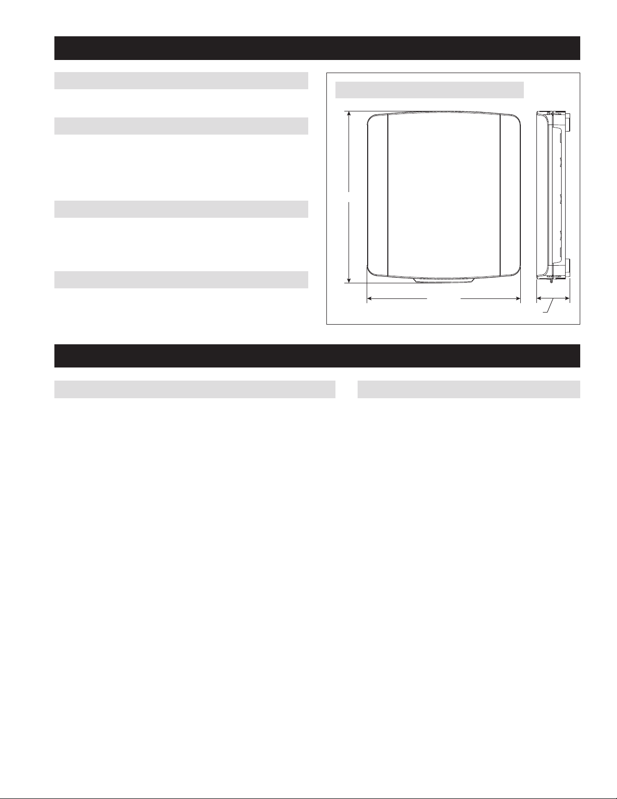
DIMENSIONS
See FIGURE 1.
8.63 (219)
9.66 (245)
1.86 (47)
90-2468
FIGURE 1 – ZONE PANEL DIMENSIONS IN INCHES (mm)
APPLICATION & ACCESSORIES
APPLICATION
The Model 6303 and 6302 Zone Panels are for heat pump applications. The
Model 6303 is for 3-zone installations and the 6302 is for 2-zone installations.
The features include:
• 2 heating and 1 cooling stage
• Equipment protection
• Vacation mode – Zone 1 thermostat controls all zones
• Emergency Heat mode – Locks out the heat pump for heating
ACCESSORIES
• Discharge Air Temperature Sensor (DAT):
Model 8052 (included)
English 3
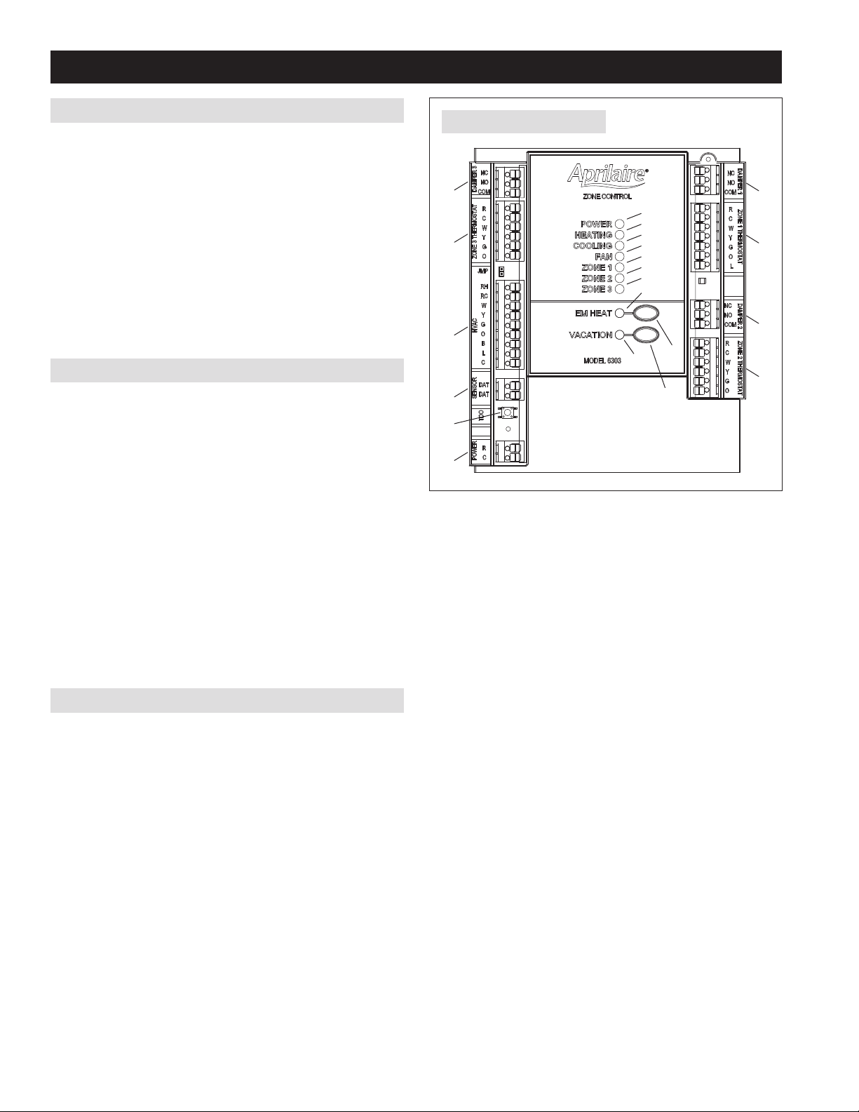
ZONE PANEL LAYOUT
TERMINALS
1. HVAC – HVAC connection
2. ZONE 1 THERMOSTAT – Thermostat connection
3. ZONE 2 THERMOSTAT – Thermostat connection
4. ZONE 3 THERMOSTAT (6303 only) – Thermostat connection
5. DAMPER 1 – Zone 1 damper connection
6. DAMPER 2 – Zone 2 damper connection
7. DAMPER 3 (6303 only) – Zone 3 damper connection
8. SENSOR DAT (Discharge Air Temperature)
9. POWER – Zone panel, thermostat and damper power
LEDs
10. POWER – Green: 24VAC is present. Flashing: TDO button is pressed.
11. HEATING – Green: Heating is active. Flashing: DAT high temperature
limit reached.
12. COOLING – Green: Cooling is active. Flashing: DAT low temperature
limit reached.
13. FAN – Green: Fan output is active.
14. ZONE 1 – Green: Damper is open. Red: Damper is closed.
15. ZONE 2 – Green: Damper is open. Red: Damper is closed.
16. ZONE 3 (6303 only) – Green: Damper is open. Red: Damper is
closed.
17. EM HEAT – Amber: Emergency Heat mode is enabled using the EM
Heat button.
18. VACATION – Green: Vacation mode is enabled.
BUTTONS
19. EM HEAT – Used to enable/disable Emergency Heat mode. In
Emergency Heat mode the heat pump will be locked out for heating
calls and only auxiliary heat will be used.
20. VACATION – Used to enable/disable Vacation mode. In Vacation
mode all zones will be controlled by the thermostat in Zone 1.
21. TDO (Time Delay Override) – Accelerates timing (6 seconds = 1
minute) used to speed up minimum on and off timers.
10
6
5
7
4
1
2
18
3
19
11
12
13
14
15
16
17
8
21
9
20
90-2144
FIGURE 2 – ZONE PANEL LAYOUT
4 English
 Loading...