


Model 1610/1620 Easy Install™ Media Air Cleaner
Installation Instructions
 WARNING
1.High voltage may cause serious injury from electrical shock. Disconnect power to the furnace/air handler before starting installation.
2.Sharp edges may cause injury from cuts. Use care when cutting and handling sheet metal.
 CAUTION
1.To prevent component failure, do not install the air cleaner on the warm air supply or in an area where the temperature may exceed 140°F. This may include areas above heat exchangers in downflow furnaces or above exhaust flues in lowboy furnace cold air returns.
2.Installation must be done by a qualified heating and air conditioning professional. Read instructions thoroughly before beginning installation.
3.Do not install air cleaner downstream of a UV light. UV lamps will cause degradation of the filtering media.
SPECIFICATIONS
|
Model 1610 |
Model 1620 |
|
|
|
Airflow Capacity |
Up to 2000 CFM maximum |
Up to 2000 CFM maximum |
|
|
|
Replacement Media |
Model 410 or 413 with SelfSeal™ |
Model 210 or 213 with SelfSeal™ |
|
|
|
Air Cleaner Operating Environment |
Temperature: 0°F – 140°F |
Temperature: 0°F – 140°F |
|
|
|
FIGURE 1 |
– AIR CLEANER DIMENSIONS |
|
B |
|
|
C |
|||
|
|
|
|
|
|
Model |
Model |
|
|
DIM |
1610 |
1620 |
|
A |
|
|
|
|
|
A |
8.1" to 10.1" |
8.1" to 10.1" |
|
|
B |
28.2" |
25.4" |
|
|
C |
24.1" |
24.1" |
|
|
D |
15.7" |
15.7" |
|
|
E |
30.1" |
27.4" |
D |
E |
F |
22.0" |
19.3" |
|
|
G |
15.5" |
19.8" |
|
|
H |
17.8" |
22.1" |
|
|
|
|
|
H |
G |
|
|
|
|
F |
10-11479 |
|
|
|
|
English 1

LOCATING THE AIR CLEANER
1.The air cleaner can be mounted on the right or left side of the HVAC equipment (FIGURE 2).
2.The door can be facing the front or rear of the HVAC equipment cabinet (FIGURE 2).
3.The door and blanking plate are reversible to allow filter access from the front or rear of the HVAC equipment cabinet (FIGURE 2).
4.Leave sufficient space for the removal of the filtering media (FIGURE 3).
FIGURE 2
The door and blanking panel are reversible to allow filter access from the front or back.
BLANKING
PLATE
|
FIGURE 3 |
|
FILTER REPLACEMENT CLEARANCE |
|
29 FOR MODEL 1610 |
|
27 FOR MODEL 1620 |
DOOR |
|
10-11481 |
10-11483 |
EASY TO INSTALL AIR CLEANER FEATURES
The air cleaner has many features to make retrofit easier:
1.The cold air return opening is adjustable between 8" and 10". This is done by bending up the appropriate tabs. The 8" dimension can be offset to the right or left by moving the “L” bracket to either side to match up with the location of the return drop.
FIGURE 4 – 8" x 24" OFFSET RIGHT |
FIGURE 5 – 8" x 24" OFFSET LEFT |
BEND UP TABS |
L BRACKET |
L BRACKET
BEND UP TABS
10-11490 |
10-11490 |
2 English
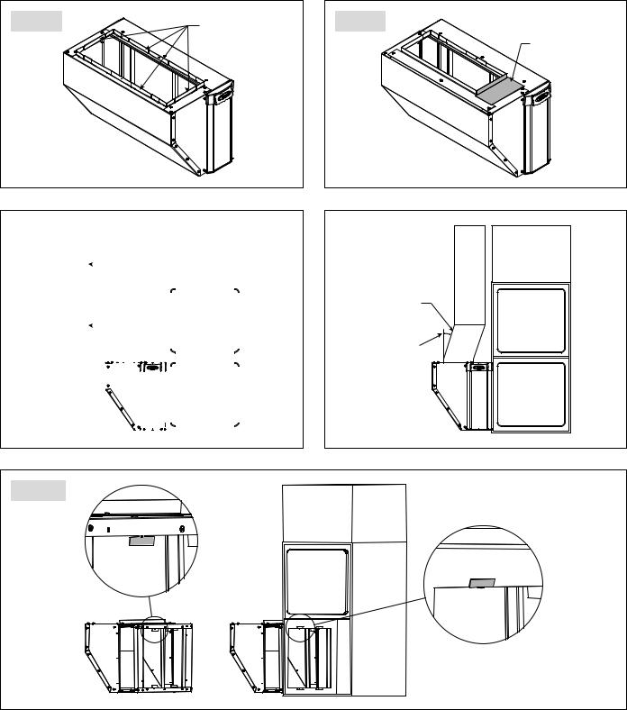
2.The “L” bracket can removed to form a 10"x 24" drop opening (FIGURE 6).
3.If the cold air drop is less than 24 inches deep an angle bracket can be field fabricated and installed to reduce the drop width (FIGURE 7).
4.The cold air return can be moved into position over the top of the air cleaner (FIGURE 8) or transition pieces field fabricated (FIGURE 9).
5.Four tabs are located on the outlet side of the air cleaner. These tabs can be bent into the cold air return opening on the HVAC equipment to hold the air cleaner in position during installation (FIGURE 10).
FIGURE 6 |
BEND ALL TABS UP |
FIGURE 7 |
|
|
FIELD FABRICATED
ANGLE BRACKET
10-11490 |
10-11490 |
FIGURE 8 |
|
|
|
|
|
|
|
|
|
|
|
|
|
|
|
|
|
|
FIGURE 9 |
|
|
|
|
|
|
|
|
|
|
|
|
|
|
|
|
|
|||||||
|
|
|
|
|
|
|
|
|
|
|
|
|
|
|
|
|
|
|
|
|
|
|
COLD AIR |
|
|
|
|
|
|
|
|
|
|
|
|
|
|
FIELD |
|||||
|
RETURN DROP |
|
|
|
|
|
|
|
|
|
|
|
|
|
|
||||||
|
|
|
|
|
|
|
|
|
|
|
|
|
|
|
FABRICATED |
||||||
|
MOVED |
|
|
|
|
|
|
|
|
|
|
|
|
|
|
||||||
|
|
|
|
|
|
|
|
|
|
|
|
|
|
|
TRANSITION |
||||||
|
|
|
|
|
|
|
|
|
|
|
|
|
|
|
|
|
|
|
|||
|
|
|
|
|
|
|
|
|
|
|
|
|
|
|
|
|
|
|
30° MAX |
|
|
|
|
|
|
|
|
|
|
|
|
|
|
|
|
|
|
|
|
|
|
||
|
|
|
|
|
|
|
|
|
|
|
|
|
|
|
|
|
|
|
ANGLE |
||
|
|
|
|
|
|
|
|
|
|
|
|
|
|
|
|
||||||
|
|
|
|
|
|
|
|
|
|
|
|
|
|
|
|
|
|
||||
|
|
|
|
|
|
|
|
|
|
|
|
|
|
|
|
|
|
|
|
|
|
|
|
|
|
|
|
|
|
|
|
|
|
|
|
|
|
|
|
|
|
|
|
|
|
|
|
|
|
|
|
|
|
|
|
|
|
|
|
|
|
|
|
|
|
|
|
|
|
|
|
|
|
|
|
|
|
|
|
|
|
|
|
|
|
|
|
|
|
|
|
|
|
|
|
|
|
|
|
|
|
|
|
|
|
|
|
|
|
|
|
|
|
|
|
|
|
|
|
|
|
|
|
|
|
|
|
|
|
|
|
10-11491 |
10-11491 |
FIGURE 10
10-11498
English 3
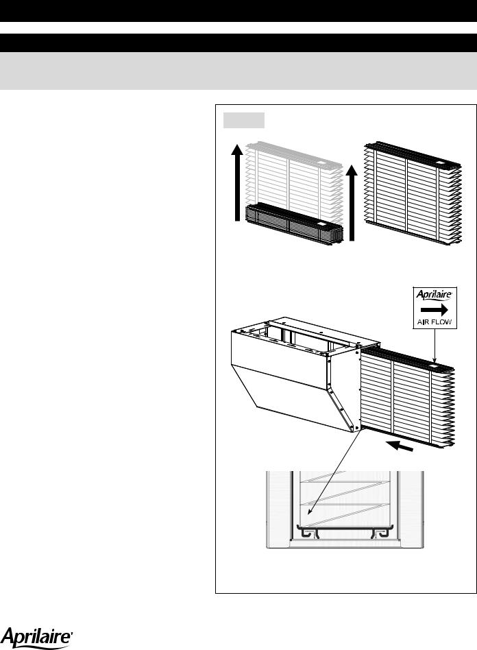
INSTALL THE AIR CLEANER CABINET
 WARNING
120 Volts may cause serious injury from electrical shock.
Disconnect power to the furnace/air handler before starting installation. Leave power disconnected until installation is completed.
1. Disconnect power to the furnace or air handler at the |
|
electrical service panel. |
FIGURE 11 |
|
2.Remove filtering media from the air cleaner cabinet.
3.If replacing an existing filter, remove the filter and thoroughly clean the blower compartment.
4.Determine which side of the furnace the air cleaner cabinet will be mounted to and set up the blanking plate accordingly.
5.Determine the cold air return drop sizing and location and bend up tabs on the top of the air cleaner cabinet accordingly.
6.Use the tabs to fix the air cleaner cabinet to the opening in the furnace. Use screws (field supplied) to mount the unit to the furnace/air handler.
7.Mount the return ductwork over the bent-up flanges on the top of the air cleaner cabinet with sheet metal screws (field supplied).
8.Seal all connections using mastic, foil tape or silicone based caulk.
9.Install the filtering media (FIGURE 11).
10.Install the door.
11.Reconnect power to the furnace or air handler at the electrical service panel.
Expand clean filter.
Install filter with Air Flow pointing toward Furnace or Air Handler.
10-11500
Align filter in top and bottom rails and slide into place. Reinstall door.
AprilairePartners.com |
Printed in USA |
P.O. Box 1467 Madison, WI 53701-1467 |
©2020 Aprilaire – A division of Research Products Corporation |
800-334-6011 F: 608-257-4357 |
10010740 B2701329C 1.20 |
4 English
 Loading...