

Page 1

K
Service Source
Macintosh LC Series/
Quadra 605
Macintosh LC, Macintosh LC II,
Macintosh LC III, Macintosh LC 475,
Macintosh Quadra 605
Page 2

K
Service Source
Basics
Macintosh LC Series/Quadra 605
Page 3
Basics Overview - 2
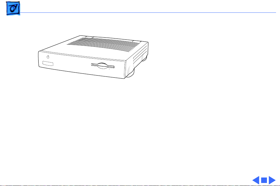
Overview
This manual includes
complete repair procedures
for the Macintosh LC Series/
Quadra 605, shown at left.
Figure: Macintosh LC Series, Quadra 605
Page 4

K
Service Source
Specifications
Macintosh LC Series/Quadra 605
Page 5

Specifications Introduction - 1
Introduction
Specifications information for this product can be found in this chapter and also in the
Spec Database, which you can access in one of three ways:
— Launch it directly by double-clicking the Apple Spec Database runtime alias at the top
level of the Main Service Source CD.
— Select "Apple Spec Database" from the Service Source drop-down main menu.
— Click the Acrobat toolbar icon for the database, which is near the right end of the
toolbar with the letters "SP."
Page 6

Specifications Processor - 2
Processor
LC
LC II
LC III
Motorola 68020 microprocessor
16 MHz
16-bit internal data bus
Motorola 68030 microprocessor
16 MHz
16-bit internal data bus
Burst-mode RAM access
Motorola 68030 microprocessor
25 MHz
32-bit internal data bus
Burst-mode RAM access
Coprocessor socket
Page 7

Specifications Processor - 3
LC 475/Quadra 605
Motorola 68LC040 microprocessor
25 MHz
32-bit internal data bus
Burst-mode RAM access
Page 8

Specifications Memory - 4
Memory
DRAM
ROM
LC: 2 MB, expandable to 10 MB (100 ns or faster SIMMs)
LC II: 4 MB standard, expandable to 10 MB (100 ns or faster
SIMMs)
LC III: 4 MB standard, expandable to 36 MB (80 ns or faster
SIMMs)
LC 475/Quadra 605: 4 MB or 8 MB standard, expandable to 36
MB (80 ns or faster SIMMs)
LC/LC II: 512 K
LC III/LC 475/Quadra 605: 512K expandable to 1 MB
Page 9

Specifications Memory - 5
VRAM
LC: 256K VRAM, upgradable to 512K
LC II: 256K VRAM SIMM, upgradable to 512K
LCIII: 512K VRAM on board, upgradable to 768K
LC 475/Quadra 605: Two 256K VRAM SIMMs, upgradable to 1MB
Page 10

Specifications Disk Storage - 6
Disk Storage
Floppy Drive
Hard Drive
LC/ LC II/ LC III: Apple SuperDrive 1.4 MB Floppy Disk Drive
Optional second internal 1.4 MB floppy drive (LC only)
LC 475/Quadra 605: Apple SuperDrive 1.4 MB Floppy Disk Drive
or Apple SuperDrive Manual Insert Floppy Disk Drive
LC: 40 MB or 80 MB
LC II: 40 MB, 80 or 160 MB
LC III: 40, 80 or 160 MB
LC 475/Quadra 605: 160 or 230 MB
Page 11

Specifications I/O Interfaces - 7
I/O Interfaces
Serial
SCSI
Apple Desktop Bus
Video
Sound
Two RS-232/RS-422 serial ports; mini DIN-8 connectors
SCSI interface; DB-25 connector
One ADB port; mini DIN-4 connector
One DB-15 monitor port for built-in video; DA-15 connector
LC/LC II/LC III: Mono sound input and output port; mini phono
plug
LC 475/Quadra 605: Mono sound input port; stereo output; mini
phono plug
Page 12

Specifications I/O Interfaces - 8
Expansion Connector
LC: 96-pin processor-direct slot (PDS) supporting 020 direct
slot expansion card
LC II: 96-pin PDS supporting 020/030 direct slot expansion
card
LC III: 114-pin PDS supporting 020/030 direct slot expansion
card
LC 475/Quadra 605: 114-pin expansion slot supporting 030/
040 expansion cards. Accepts Macintosh LC compatible I/O
display, network, and video capture cards. Does not support
030 processor accelerator or cache cards.
Page 13

Specifications I/O Devices - 9
I/O Devices
Keyboard
Mouse
Microphone
Apple Keyboard, Apple Keyboard II, Apple Extended Keyboard II,
or Apple Adjustable Keyboard connected through ADB ports
(mini DIN-4)
ADB mouse and ADB Mouse II connected through ADB ports (mini
DIN-4)
Electret, omnidirectional
Operates on 8 VDC supplied by microphone port on CPU
Page 14

Specifications Sound and Video - 10
Sound and Video
Sound
Video
Monaural, 8-bit sound input at 11 or 22 kHz
LC, LC II, LC III: Monophonic, 8-bit sound generator supplying
same signal to both channels of stereo equipment
LC 475 and Quadra 605: Stereo output capability
LC and LC II provide built-in support for many monitors,
including
• Apple High-Resolution Monochrome Monitor
• AppleColor High-Resolution RGB Monitor
• Macintosh 12-Inch RGB Display
• Macintosh 12-Inch Monochrome Display
• Macintosh Color Display
• Apple Basic Color Monitor
Page 15

Specifications Sound and Video - 11
Video (cont’d)
LC III, LC 475 and Quadra 605 provide up to 16-bit support on
12-, 13-, and 16-inch monitors and 8-bit support on 15inch portrait and 21-inch monitors. LC III, LC 475 and Quadra
605 support all Apple monitors available at CPU introduction
dates, including
• Apple High-Resolution Monochrome Monitor
• AppleColor High-Resolution RGB Monitor
• Macintosh 12-Inch RGB Display
• Macintosh 12-Inch Monochrome Display
• Macintosh Color Display
• Apple Basic Color Monitor
• Macintosh 16-Inch Color Display (Macintosh LC III only)
LC III, LC 475 and Quadra 605 support NTSC and PAL.
Page 16

Specifications Electrical - 12
Electrical
Line V oltage
Frequency
Maximum Power
100–240 VAC, automatically configured
LC Series: 47–63 Hz
Quadra 605: 50–60 Hz
LC/LC II: 50 W (not including monitor)
LC III: 30 W
Quadra 605: 26 W
Page 17

Specifications Physical - 13
Physical
Dimensions
Weight
Height: 3.0 in. (7.7 cm)
Width: 12.2 in. (31.0 cm)
Depth: 15.0 in. (38.2 cm)
8.8 lb. (4.0 kg)
Page 18

K
Service Source
Troubleshooting
Macintosh LC Series/Quadra 605
Page 19

Troubleshooting General/ - 1
General
The Symptom Charts included in this chapter will help you
diagnose specific symptoms related to your product. Because cures
are listed on the charts in the order of most likely solution, try
the first cure first. Verify whether or not the product continues to
exhibit the symptom. If the symptom persists, try the next cure.
(Note: If you have replaced a module, reinstall the original module
before you proceed to the next cure.)
If you are not sure what the problem is, or if the Symptom Charts
do not resolve the problem, refer to the Flowchart for the product
family.
For additional assistance, contact Apple Technical Support.
Page 20

Troubleshooting Symptom Charts/Error Chords - 2
Symptom Charts
Error Chords
Error chord sounds
during startup
(Macintosh LC)
Eight-tone error
chord sounds during
startup (LC II/III/
475/Quadra 605)
1 Replace SIMMs.
2 Perform SIMM verification on replacement logic board.
3 Replace logic board. Retain customer’s SIMMs.
1 Replace SIMMs.
2 Perform SIMM verification on replacement logic board.
3 Replace logic board. Retain customer’s SIMMs.
Page 21

Troubleshooting Symptom Charts/Error Chords
(Continued)
- 3
Four-tone error
chord sounds during
startup (Macintosh
LC II)
Error Chords
1 Disconnect hard drive power cable and hard drive data cable
and reboot system. If startup sequence is normal, run
“Macintosh Hard Disk Test” and replace hard drive if
necessary.
2 Disconnect floppy drive cable and reboot system. If startup
sequence is normal, replace floppy drive.
3 Replace logic board. Retain customer’s SIMMs.
(Continued)
Page 22

Troubleshooting Symptom Charts/Built-in Video - 4
Built-in Video
Screen is dark, audio
and at least one drive
operate, fan runs,
and LED is lit
Screen is dark, audio
and drive do not
operate, but fan runs
and LED is lit
1 Adjust brightness on monitor.
2 Try monitor with another Macintosh computer.
3 Check battery.
4 Replace monitor. Troubleshoot defective monitor. See
Symptom Charts in appropriate monitor manual.
5 Replace video cable.
6 Replace VRAM SIMM.
7 Replace logic board. Retain customer’s SIMMs.
8 Replace power supply.
1 Remove expansion card, if present.
2 Remove peripherals.
3 Disconnect hard drive and floppy drive.
4 Replace SIMMs. Refer to Memory manual.
5 Replace logic board. Retain customer’s SIMMs.
6 Replace power supply.
Page 23

Troubleshooting Symptom Charts/Built-in Video
(Continued)
- 5
Partial or whole
screen is bright and
audio is present, but
no video information
is visible
Screen is completely
dark, fan is not
running, and LED is
not lit
Built-in Video
1 Verify monitor works with another Macintosh.
2 Replace video cable.
3 Replace monitor.
4 Replace logic board. Retain customer’s SIMMs.
1 Plug monitor directly into wall socket. Verify that monitor
has power.
2 Remove expansion card, if present.
3 Remove peripherals.
4 Disconnect hard drive and floppy drive.
5 Replace power supply.
6 Replace logic board. Retain customer’s SIMMs.
(Continued)
Page 24

Troubleshooting Symptom Charts/Built-in Video
(Continued)
- 6
Vertical lines,
horizontal lines, or
snow appears on
screen, or screen is
completely dark;
startup tone is
normal
Built-in Video
1 Verify monitor works with another Macintosh.
2 Replace video cable.
3 Replace monitor.
4 Replace VRAM SIMM.
5 Replace logic board. Retain customer’s SIMMs.
6 Replace power supply.
(Continued)
Page 25

Troubleshooting Symptom Charts/Floppy Drive - 7
Floppy Drive
Audio and video are
present, but internal
drive does not operate
Disk ejects; display
shows Mac icon with
blinking “X”
Disk does not eject 1 Switch off system and hold mouse button down while
1 Replace floppy drive cable.
2 Replace floppy drive.
3 Replace logic board. Retain customer’s SIMMs.
1 Replace disk with known-good system disk.
2 Replace floppy drive cable.
3 Replace floppy drive.
4 Replace logic board. Retain customer’s SIMMs.
switching system back on.
2 Remove top cover.
3 Eject disk manually by pushing opened paper clip into hole
beside drive slot.
4 Replace floppy drive cable.
5 Replace floppy drive.
Page 26

Troubleshooting Symptom Charts/Floppy Drive
(Continued)
- 8
Drive attempts to
eject disk, but doesn’t
Floppy Drive
1 Push disk completely in.
2 Eject disk manually by pushing opened paper clip into hole
beside drive slot.
3 Check that cover is completely on.
4 Replace floppy drive.
(Continued)
Page 27

Troubleshooting Symptom Charts/Hard Drive - 9
Hard Drive
Internal hard drive
runs continuously
Internal hard drive
does not operate
1 Make sure System is version 6.0.7 (or later) for Macintosh
LC, version 7.0.1 (or later) for Macintosh LC II, or version
7.1 (or later) for LC III/475 and Quadra 605.
2 Replace hard drive cable.
3 Replace internal hard drive.
4 Replace logic board. Retain customer’s SIMMs.
1 Replace hard drive data cable.
2 Replace hard drive power cable.
3 Replace internal hard drive.
4 Replace logic board. Retain customer’s SIMMs.
Page 28

Troubleshooting Symptom Charts/Peripherals - 10
Peripherals
Works with internal
or external SCSI
device but does not
work with both
Cursor does not move 1 Reboot system.
1 Verify that SCSI select switch on external device is set to
different priority from internal.
2 Verify that both ends of external SCSI device are terminated.
3 Replace terminator on external device.
4 Verify that terminator is installed on internal SCSI drive.
5 Replace SCSI select cable.
2 Check mouse connection.
3 If mouse was connected to keyboard, connect mouse to rear
ADB port and disconnect keyboard. If mouse works, replace
keyboard.
4 If mouse does not work in any ADB port, replace mouse.
5 Remove additional PDS cards.
6 Reset PRAM.
7 Replace logic board. Retain customer’s SIMMs.
Page 29

Troubleshooting Symptom Charts/Peripherals
(Continued)
- 11
Cursor moves, but
clicking mouse
button has no effect
Double-click doesn’t
open application,
disk, or server
Peripherals
1 Replace mouse.
2 Replace logic board. Retain customer’s SIMMs.
1 Remove extra system files on hard drive.
2 Clear parameter RAM. System 7: Hold down <Command>
<Option> <P> <R> during startup but before “Welcome to
Macintosh” appears. System 6 and earlier: Hold down
<Command> <Option> <Shift> keys and select Control Panel
from Apple menu.
3 If mouse was connected to keyboard, connect mouse to rear
ADB port and disconnect keyboard. If mouse works, replace
keyboard.
4 If mouse does not work in any ADB port, replace mouse.
5 Replace logic board. Retain customer’s SIMMs.
(Continued)
Page 30

Troubleshooting Symptom Charts/Peripherals
(Continued)
- 12
No response to any
key on keyboard
Peripherals
1 Make sure System is version 6.0.7 (or later) for Macintosh
LC, version 7.0.1 (or later) for Macintosh LC II, or version
7.1 (or later) for LC III/475 and Quadra 605.
2 Check keyboard connection to ADB port.
3 Replace keyboard cable.
4 Replace keyboard.
5 Remove battery for 15 to 30 minutes to reset logic board.
6 Replace logic board. Retain customer’s SIMMs.
(Continued)
Page 31

Troubleshooting Symptom Charts/Peripherals
(Continued)
- 13
Known-good
LaserWriter does not
print
Known-good
ImageWriter or
ImageWriter II does
not print
Peripherals
1 Make sure that Chooser and Control Panel settings are
correct.
2 Make sure System is version 6.0.7 (or later) for Macintosh
LC, version 7.0.1 (or later) for Macintosh LC II, or version
7.1 (or later) for LC III/475 and Quadra 605.
3 Reset PRAM.
1 Make sure that Chooser and Control Panel settings are
correct.
2 Make sure System is version 6.0.7 (or later) for Macintosh
LC, version 7.0.1 (or later) for Macintosh LC II, or version
7.1 (or later) for LC III/475 and Quadra 605.
3 Check printer DIP switches.
4 Reset PRAM.
5 Replace printer interface cable.
6 Replace logic board. Retain customer’s SIMMs.
(Continued)
Page 32

Troubleshooting Symptom Charts/Miscellaneous - 14
Miscellaneous
Clicking, chirping,
or thumping
System shuts down or
restarts
intermittently
1 Disconnect hard drive. Replace drive if noise disappears.
2 Replace power supply.
3 Replace logic board. Retain customer’s SIMMs.
1 Make sure air vents on back and top of case are unobstructed.
Thermal protection circuitry may shut down computer. After
30 to 40 minutes, system should be OK.
2 Replace power cable.
3 Install standoffs on LC Ethernet Card, if present.
4 Replace power supply.
5 Replace SIMMs. Refer to Memory manual.
6 Replace logic board. Retain customer’s SIMMs.
Page 33

Troubleshooting Symptom Charts/Miscellaneous
(Continued)
- 15
System
intermittently
crashes or locks up
No sound from
speaker
Miscellaneous
1 Make sure System is version 6.0.7 (or later) for Macintosh
LC, version 7.0.1 (or later) for Macintosh LC II, or version
7.1 (or later) for LC III/475 and Quadra 605.
2 Make sure software is known-good.
3 Replace logic board. Retain customer’s SIMMs.
4 Replace SIMMs.
5 Replace power supply.
1 Verify that volume setting in Control Panel is 1 or above.
2 Reset PRAM.
3 Verity nothing is connected to sound-out port.
4 Replace speaker.
5 Replace logic board. Retain customer’s SIMMs.
(Continued)
Page 34

Troubleshooting Symptom Charts/Miscellaneous
(Continued)
- 16
System seems to boot,
then message “Finder
is old version”
displays
System
intermittently doesn’t
power on
Miscellaneous
1 Clear parameter RAM. System 7: Hold down <Command>
<Option> <P> <R> during startup but before “Welcome to
Macintosh” appears. System 6 and earlier: Hold down
<Command> <Option> <Shift> keys and select Control Panel
from Apple menu.
2 Replace logic board. Retain customer’s SIMMs.
1 Check cables.
2 Plug monitor directly into wall socket. Verify that monitor
has power.
3 Try known-good keyboard and ADB cable.
4 Replace power cord.
5 Check batteries. See “Battery Verification” in Additional
Procedures.
6 Replace logic board. Retain customer’s SIMMs.
(Continued)
Page 35

Troubleshooting Symptom Charts/Miscellaneous
(Continued)
- 17
Monitor raster width
too narrow
Stand-alone system
hangs or crashes
Miscellaneous
Refer to Adjustments section in the appropriate monitor manual
for horizontal size (width) adjustment.
1 If using an older LC Ethernet card with a computer running
System 7, disable virtual memory.
2 Clear parameter RAM. System 7: Hold down <Command>
<Option> <P> <R> during startup but before “Welcome to
Macintosh” appears. System 6 and earlier: Hold down
<Command> <Option> <Shift> keys and select Control Panel
from Apple menu.
3 Upgrade to latest revision of software.
4 Remove additional RAM and PDS card.
5 Replace logic board
(Continued)
Page 36

Troubleshooting Symptom Charts/Miscellaneous
(Continued)
- 18
Miscellaneous
Networked 33 MHz
LC III freezes
Clock doesn’t run 1 Replace battery. See “Battery Replacement” in Additional
System doesn’t
recognize more than
10 MB of RAM (LC/LC
II)
1 Verify 10Base-T cable is secure.
2 Replace 10Base-T adapter card.
3 Remove additional RAM and external SCSI devices.
4 Replace logic board.
Procedures.
2 Reset PRAM.
3 Verify nothing is connected to sound-out port.
4 Replace logic board. Retain customer’s SIMMs.
Although you can install up to12 MB of RAM in Macintosh LC/LC II
computers, 10 MB is the maximum amount of RAM that the
system recognizes.
(Continued)
Page 37

K
Service Source
T ak e Apart
Macintosh LC Series/Quadra 605
Page 38

Take Apart Top Cover - 1
Quadra 605
LC/LC II/LC III/
LC 475
Top Cover
No preliminary steps are
required before you begin
this procedure.
1 Remove the case screw if
one is present.
2 Lift the tabs at the back
of the lid.
3 Lift the top cover
straight up.
Page 39

Take Apart Hard Drive - 2
Hard Drive
Before you begin, remove
Hard Drive
the top cover.
Caution:
precautions in Bulletins/
Safety.
Review the ESD
Page 40

Take Apart Hard Drive - 3
Hard Drive
Power Cable
Hard
Drive
Power
Connector
Hard Drive
Data Cable
1 Release the locking tab
and disconnect the hard
drive power cable from
the connector on the
logic board.
2 Disconnect the hard
drive data cable from the
connector on the logic
board.
Hard Drive Data
Cable Connector
Page 41

Take Apart Hard Drive - 4
3 Release the two plastic
latches on one side of the
hard drive and lift the
drive slightly. Repeat on
the other side of the
drive and remove the
drive (with carrier)
from the computer.
Replacement Note:
information on removing the
hard drive from the carrier
and returning drives,
cables, and carriers to
Apple, refer to “Additional
Procedures” in the Hard
Drives manual.
For
Page 42

Take Apart Fan/Speaker Assembly (LC) - 5
Fan/Speaker Assembly (LC)
Fan/Speaker
Assembly
Before you begin, remove
the top cover.
Caution:
precautions in Bulletins/
Safety.
Review the ESD
Page 43

Take Apart Fan/Speaker Assembly (LC) - 6
1 Release the latch on one
Latch
end of the fan/speaker
assembly, and lift the
assembly slightly.
Latch
2 Release the other latch
and remove the fan/
speaker assembly from
the bottom case.
Page 44

Take Apart Fan (LC II/III) - 7
Fan (LC II/III)
Before you begin, remove
the top cover.
Fan
Caution:
precautions in Bulletins/
Safety.
Review the ESD
Page 45

Take Apart Fan (LC II/III) - 8
1 Disconnect the fan cable
from the fan connector
on the logic board.
Fan Cable
Fan
Connector
Latch
Latch
2 Release the plastic
latches and lift the fan
from the case.
Replacement Caution:
Be
sure to install the fan with
the logo side down, or the fan
may damage the computer.
Page 46

Take Apart Speaker (LCII/III) - 9
Speaker (LCII/III)
Before you begin, remove
the following:
Speaker
• Top cover
• Hard drive
Caution:
precautions in Bulletins/
Safety.
Review the ESD
Page 47

Take Apart Speaker (LCII/III) - 10
1 Disconnect the speaker
cable from the speaker
connector on the logic
board.
Speaker Cable
Speaker
Connector
Latch
Speaker
Latch
2 Release the plastic
latches and lift the
speaker from the case.
Replacement Note:
Before
reconnecting the speaker
cable, thread it through the
top two brackets that hold
the hard drive in place.
Page 48

Take Apart Floppy Drive - 11
Floppy Drive
Before you begin, remove
Floppy Drive
the top cover.
Caution:
precautions in Bulletins/
Safety.
Review the ESD
Page 49

Take Apart Floppy Drive - 12
Floppy Drive
Cable
Floppy Drive Cable Connector
Macintosh LC
1 Disconnect the floppy
drive cable from the
connector on the logic
board.
Note:
Retain the old
floppy drive cable. Use
the old cable on the new
exchange module.
2 Release the two latches
on one side of the drive
and lift the drive
slightly. Repeat on the
other side and remove
the drive from the case.
Page 50

Take Apart Floppy Drive - 13
Replacement Note:
you install a replacement
1.4 MB SuperDrive, you
must remove the dust shield.
Before
Page 51

Take Apart Floppy Drive - 14
LC II/LC III/Quadra 605
Floppy Drive
Connector
Latch
Latch
Floppy
Drive
1 Disconnect the floppy
drive cable from the
connector on the logic
board.
2 Release the two latches
at the rear of the floppy
drive and remove the
drive from the case.
Replacement Note:
you install a replacement
auto-inject 1.4 MB
SuperDrive, you must
remove the dust shield, if
present.
Before
Page 52

Take Apart Floppy Drive - 15
Replacement Note:
encounter either an Apple
SuperDrive or a manual
eject floppy drive in some
models. Replace floppy
drives like for like.
You may
Page 53

Take Apart Power Supply - 16
Power Supply
Before you begin, remove
the top cover.
Power Supply
Caution:
precautions in Bulletins/
Safety.
Review the ESD
Page 54

Take Apart Power Supply - 17
1 Disconnect the power
supply cable from the
connector on the logic
board.
Power
Supply
Cable
Power
Supply
Connector
2 Release the two latches
that secure the front end
of the power supply to
the bottom case, and lift
the power supply out of
the case.
Page 55

Take Apart Logic Board - 18
Logic Board
Before you begin, remove
the following:
• Top cover
• Fan/speaker assembly
(LC)
• Fan (LC II/III/475 and
Quadra 605)
Logic Board
Caution:
precautions in Bulletins/
Safety.
Review the ESD
Page 56

Take Apart Logic Board - 19
1 Disconnect the following
Power Supply Cable
cable connectors from
the logic board:
Floppy Drive
Cable
• Hard drive power
cable
• Hard drive data cable
Fan Cable
Speaker Cable
• Floppy drive cable
• Power supply cable
• Fan cable (LC II/III/
Hard Drive
Data Cable
LC 475 and Quadra
605)
• Speaker cable (LC II/
III/LC 475 and
Hard Drive
Power Cable
Expansion
Connector
Expansion Card
Quadra 605)
2 Remove the expansion
card (if installed).
Page 57

Take Apart Logic Board - 20
Caution:
be sure the power on/off
button clears the rear panel
before you remove the logic
board. While lifting the
board, do not touch any
components or connectors on
the back of the logic board.
(The oil from your skin can
harm the connectors.)
In the next step,
Page 58

Take Apart Logic Board - 21
3 Using your forefingers,
spread the two latches
that secure the logic
board to the bottom case.
At the same time, using
Latch
your right thumb, push
on the expansion
connector and slide the
logic board toward the
front of the case.
Latch
Expansion Connector
Page 59

Take Apart Logic Board - 22
4 Gently lift the board
from the case.
Replacement Note:
the SIMMs from the
defective logic board and
install them on the
replacement logic board.
Remove
Page 60

Take Apart Logic Board - 23
Quadra 605 Logic Board
J18
Jumper
5 Remove the jumper from
the pins at location J18
on the defective board.
Replacement Note:
The
LC 475 and Quadra 605
use the same logic board
replacement. The Quadra
605 requires a jumper
to connect the pins at
location J18. Quadra
605 service
replacement logic boards
do not include the
jumper.
Page 61

Take Apart Logic Board - 24
Quadra 605 Logic Board
6 Install a jumper on the
pins at location J18 on
the Quadra 605 service
replacement logic board.
Jumper
J18
Page 62

Take Apart Logic Board - 25
Grounding Pad
Foam
Connecting
Grounding Spring
Replacement Note:
The
replacement logic boards for
the LC 475 and the Quadra
605 do not include
grounding connectors. You
must remove the grounding
connector from the
defective board and install
it on the replacement board.
There are two versions of
grounding connectors, a
foam grounding pad and a
connecting grounding
spring. You may encounter
either version on LC 475
and Quadra 605 logic boards.
Page 63

Take Apart Logic Board - 26
Foam Grounding
Pad
Connecting
Grounding Spring
Audio Ports
Rough Side
Out
Audio Ports
7 Install the foam
grounding pad on the
audio ports of the
replacement logic board
with the rough side of
the pad facing out.
8 Install the connecting
grounding spring on the
audio ports of the
replacement logic board
with the arms of the
spring facing out.
Spring
Arms
Out
Page 64

K
Service Source
Upgrades
Macintosh LC Series/Quadra 605
Page 65

Upgrades LC Ethernet Upgrade - 1
LC Ethernet Upgrade
Before you begin, remove
the top cover.
LC Ethernet Card
Caution:
precautions in Bulletins/
Safety.
Note:
Ethernet Card package
includes the LC Ethernet
Card and standoffs. If you
order service parts, you
must order the standoffs
separately from the card.
Review the ESD
The finished goods LC
Page 66

Upgrades LC Ethernet Upgrade - 2
1 Insert the short standoff
in the hole on the corner
near the connector end of
Long Standoff
the card.
2 Insert the long standoff
in the hole on the center
edge of the card.
Short Standoff
Caution:
Failure to
install the standoffs can
cause the computer to
restart intermittently.
Page 67

Upgrades LC Ethernet Upgrade - 3
LC Ethernet Card
LC Ethernet Card
External Connector
3 Position the card so that
the external connector
extends through the
expansion connector
opening.
4 Pivot the card over the
expansion slot.
5 Press the connector
pins into the connector
slot.
Note:
Do not force the card
into the slot. If you meet a
lot of resistance, pull the
card out and reseat it.
Page 68

Upgrades LC II Upgrade - 4
LC II Upgrade
Before you begin, remove
the following:
Macintosh LC Logic Board
• Top cover
• Fan/speaker assembly
• Logic board
Caution:
precautions in Bulletins/
Safety.
Note:
upgrade kit upgrades a
Macintosh LC to a Macintosh
LC II. The upgrade kit
includes a Macintosh LC II
logic board and cover.
Review the ESD
A Macintosh LC II
Page 69

Upgrades LC II Upgrade - 5
1 Install the Macintosh LC
II logic board.
Macintosh LC II Logic Board
2 Install the customer’s
SIMMs into the new logic
board.
Page 70

Upgrades LC II Upgrade - 6
Sound-Out Port
Sound Input Port
Replacement Note:
After
replacing the fan/speaker
assembly, install the
Macintosh LC II top cover.
Make sure that the
connections to the soundout and sound input ports
are correct. Inserting
equipment into the wrong
port can damage the
computer or equipment.
Page 71

Upgrades LC to LC III Upgrade - 7
LC to LC III Upgrade
Before you begin, remove
Macintosh LC III Upgrade
the following:
• Top cover
• Fan/speaker assembly
• Floppy drive
• Logic board
Caution:
precautions in Bulletins/
Safety.
Review the ESD
Page 72

Upgrades LC to LC III Upgrade - 8
Note:
A Macintosh LC III
upgrade kit includes LC III
logic board, bottom case,
top cover, power supply,
speaker, fan, and floppy
drive carrier.
Note:
You will use only a
few parts from the original
LC in upgrading an LC to an
LC III. The following
procedures explain how to
remove the LC parts and
install them into the LC III
upgrade unit.
Page 73

Upgrades LC to LC III Upgrade - 9
1 Remove the Macintosh LC
floppy drive and floppy
drive cable. (See
“Floppy Drive” in Take
Apart.)
2 Remove the floppy drive
and cable from the LC
LC Floppy Drive Carrier
Floppy Drive Cable Apple 1.4 MB SuperDrive
floppy drive carrier.
Page 74

Upgrades LC to LC III Upgrade - 10
3 Install the floppy drive
with cable into the LC III
floppy drive carrier.
LC III Upgrade Floppy
Drive Carrier
Apple 1.4 MB SuperDrive
Floppy Drive Cable
Page 75

Upgrades LC to LC III Upgrade - 11
4 Install the floppy drive
1.4 MB SuperDrive in
LC III Upgrade Carrier
into the floppy drive
bay of the LC III upgrade
bottom case.
5 Connect the floppy drive
cable to the floppy drive
connector on the logic
board.
LC III Floppy Drive Bay
Floppy Drive
Cable Connector
LC III Bottom Case
Replacement Note:
If you
are installing a replacement
auto-inject 1.4 MB
SuperDrive, you must
remove the dust shield, if
present.
Page 76

Upgrades LC to LC III Upgrade - 12
6 Remove the Macintosh LC
Hard Drive
Data Cable
LC Hard Drive
with Carrier
hard drive with
carrier, hard drive data
cable, and hard drive
power cable. (See “Hard
Drive” in Take Apart.)
7 Install the LC hard drive
into the hard drive bay
of the LC III upgrade
LC III Hard Drive Bay
Hard Drive
Power Cable
bottom case.
8 Connect the hard drive
data cable and hard
drive power cable
connectors to the
connectors on the LC III
upgrade logic board.
LC III Bottom Case
Page 77

Upgrades LC to LC III Upgrade - 13
9 Install the LC VRAM
SIMMs and the expansion
card (if present) into
the LC III upgrade logic
board.
Note:
DRAM SIMMs
from an LC are not
compatible with the LC
III.
10 Attach the top cover.
Page 78

Upgrades LC II to LC III Upgrade - 14
LC II to LC III Upgrade
Before you begin, remove
Macintosh LC III Upgrade
the top cover.
Caution:
precautions in Bulletins/
Safety.
Review the ESD
Page 79

Upgrades LC II to LC III Upgrade - 15
Note:
A Macintosh LC III
upgrade kit upgrades a
Macintosh LC II to a
Macintosh LC III. The
upgrade kit includes a
Macintosh LC III logic board,
top cover, fan, speaker, and
a floppy drive carrier.
When upgrading an LC II to
an LC III, you will need only
the LC III logic board.
Page 80

Upgrades LC II to LC III Upgrade - 16
1 Install the Macintosh LC
III logic board. (See Take
Apart chapter.)
Macintosh LC III Logic Board
Page 81

Upgrades LC II to LC III Upgrade - 17
2 Install the fan and new
Macintosh LC III top
cover (see Take Apart
chapter).
Sound-Out Port
Sound Input Port
Replacement Caution:
Make
sure that the connections to
the sound-out and sound
input ports are correct.
Inserting equipment into
the wrong port can damage
the computer or equipment.
Page 82

Upgrades LC 475 Logic Board Upgrade - 18
LC 475 Logic Board Upgrade
Macintosh LC II or III
Logic Board
Before you begin, remove
the following:
• Top cover
• Fan
• Logic board
Caution:
precautions in Bulletins/
Safety.
Review the ESD
Page 83

Upgrades LC 475 Logic Board Upgrade - 19
Note:
A Macintosh LC 475
upgrade kit upgrades a
Macintosh LC II or III to a
Macintosh LC 475. The
upgrade kit includes a
Macintosh LC 475 logic
board and product ID labels.
Page 84

Upgrades LC 475 Logic Board Upgrade - 20
1
Note:
The upgrade kit
does not include a
connecting grounding
spring. You must order
Audio Ports
this part separately.
Before installing the
upgrade logic board,
install the connecting
grounding spring on the
audio ports of the board,
with the arms of the
spring facing out.
Connecting Grounding Spring
Page 85

Upgrades LC 475 Logic Board Upgrade - 21
2 Install the Macintosh LC
475 logic board.
Macintosh LC 475 Logic Board
Page 86

Upgrades LC 475 Logic Board Upgrade - 22
3 Install the fan and top
cover (see Take Apart
chapter).
Page 87

Upgrades Macintosh Processor Upgrade - 23
Macintosh
Macintosh Processor Upgrade
(including 256K Cache Card)
Processor Upgrade
Before you begin, remove
the following:
• Top cover
• I/O door
• Logic board
• Card in the PDS slot (if
any)
Caution:
precautions in Bulletins/
Safety.
Review the ESD
Page 88

Upgrades Macintosh Processor Upgrade - 24
Note:
Macintosh Processor
Upgrade with
256K Cache Card
Hook-and-Loop
Fasteners
The Macintosh
Processor Upgrade kit
allows 68LC040 computers
to switch between a
PowerPC 601 processor
and a 68LC040 processor.
The upgrade board includes
040 Heat
Sink
the PowerPC 601 processor
on board and a socket to
accept the customer’s
68LC040 processor.
Note:
Refer to the Macintosh
Processor Upgrade manual
under the Power Macintosh
256K Cache
Card
Spacer
Processor Removal Tool
menu for information about
specifications and
troubleshooting.
Page 89

Upgrades Macintosh Processor Upgrade - 25
Note:
The Macintosh
Processor Upgrade comes
packaged with the Macintosh
Processor Upgrade board,
256K cache card, 040 heat
sink, and hook-and-loop
fasteners. If you need to
order service replacement
parts, order the parts
separately.
Note:
To install the upgrade,
you will need a processor
removal tool. Order the
removal tool as a separate
service part.
Page 90

Upgrades Macintosh Processor Upgrade - 26
Note:
The cache card comes
installed on the upgrade
board.
Page 91

Upgrades Macintosh Processor Upgrade - 27
Installation Procedure Overview
There are three basic steps
to installing the Macintosh
Processor Upgrade on LC
475 and Quadra 605
computers.
• Remove the 68LC040
processor from the
customer’s logic board
• Install the 68LC040
processor on the upgrade
board
• Install the upgrade board
on the logic board
Detailed procedures follow.
Page 92

Upgrades Macintosh Processor Upgrade - 28
1 Locate the 68LC040
processor on the logic
board.
2 Remove the 68LC040
processor from the logic
board
68LC040
Processor
Page 93

Upgrades Macintosh Processor Upgrade - 29
Note:
Processor
This graphic
shows the proper way to
remove any 68LC040
chip from its logic
board. Your logic board
may differ somewhat
from this graphic
3 Position the teeth of the
processor removal tool
in the groove between
the processor and the
logic board socket.
Processor
Removal Tool
Processor Socket
Page 94

Upgrades Macintosh Processor Upgrade - 30
Caution:
up on the handle of the
processor removal tool.
Pressing down could
damage components on
the logic board.
Caution:
side of the processor
only slightly to avoid
bending the pins.
4 Gently lift up the
processor removal tool
handle and pry up each
side of the processor
from the socket.
5 Remove the processor.
Be sure to lift
Pry up each
Page 95

Upgrades Macintosh Processor Upgrade - 31
Install the 68LC040
Processor on the
Upgrade Board
Alignment Corners
Spacer
68LC040 Processor
Note:
The alignment corner
of the 68LC040 processor is
missing one pin. The
alignment corner of the
spacer is missing a pin hole.
1 Position the spacer
alignment corner over
the 68LC040 processor
alignment corner
2 Place the spacer on the
processor.
Page 96

Upgrades Macintosh Processor Upgrade - 32
68LC040
Processor
Caution:
Forcing the
68LC040 processor
connector pins into the
socket could damage the pins.
If the processor resists
installation, check the pin
alignment.
Caution:
Place the upgrade
board on a firm even surface
to avoid bending the upgrade
board when pressing the
processor into the socket.
Caution:
Use two thumbs to
evenly distribute the
pressure as you press the
processor into the socket.
Page 97

Upgrades Macintosh Processor Upgrade - 33
3 Hold the processor and
spacer together and
position the spacer
alignment corner over
the upgrade socket
alignment corner.
4 Press the processor
connector pins into the
socket until you hear a
“snap.”
Page 98

Upgrades Macintosh Processor Upgrade - 34
Note:
On a correctly
installed 040 processor, a
very small gap separates the
040 chip from the metal
040 Processor
spacer. A larger gap caused
by the board barrel sockets
Spacer
separates the upgrade board
and the spacer.
Small Gap
Barrel Sockets
Page 99

Upgrades Macintosh Processor Upgrade - 35
5 Peel the paper from the
back of the heat sink and
install the heat sink on
the processor.
040 Heat Sink
Note:
Make sure the
040 heat sink is aligned
with the sides of the
processor.
68LC040
Processor
Page 100

Upgrades Macintosh Processor Upgrade - 36
Install the Upgrade Board
Note:
The next step explains
how to prepare the logic
Anti-Static Foam
Logic Board,
Bottom Side
EMI Clip
board to accept the upgrade
board.
Caution:
the bottom of the LC 475 and
Quadra 605 logic boards flex
easily. Do not apply heavy
pressure directly to these
clips or to the logic board,
or you may bend the board.
The EMI clips on
 Loading...