

Page 1

K
Service Source
Power Macintosh 7200
Series/WS 7250
Power Macintosh 7200/75, 7200/90, 7200/120 and
WS 7250/120
Page 2

K
Service Source
Basics
Power Macintosh 7200 Series/
WS 7250
Page 3

Basics Overview - 1
Overview
The chassis design of the Power Macintosh 7200 Series and
WS 7250 computers allows you to access the logic board and
its components without having to remove the power supply
or any drives. This flexible design makes these computers
easier to service and upgrade.
Features of the Power Macintosh 7200 Series include
• A 75, 90, or 120 MHz PowerPC™ 601 microprocessor
with built-in FPU and optional Level 2 cache
• Three PCI expansion slots
• 5 MB per second internal and external SCSI channels
• DRAM expansion up to 256 MB using 168-pin, 70 ns,
64-bit DIMMs
• 1 MB of soldered VRAM, expandable to 2 or 4 MB
• Built-in AAUI and 10BASE-T Ethernet
• Two GeoPort serial ports
Page 4

Basics Overview - 2
• AppleCD™ 600i or 1200i CD-ROM drive
• CD-quality stereo sound in/out
• Optional PC Compatibility Card (Power Macintosh
7200/120)
• Mac™ OS system software 7.5.2 (7200/75 and
7200/90), system software7.5.3 (7200/120), and
system software7.5.3 Revision 2 (7200/120 8x-CD)
Note
: VRAM expansion works as follows: 1 MB of VRAM is
soldered to the board. To go to 2 MB, install one 1 MB VRAM
DIMM in slot 1. To go to 4 MB, install three 1MB VRAM
DIMMs in slots 1, 2, and 3.
Features of the Workgroup Server 7250/120 include
• A 120 MHz PowerPC™ 601 microprocessor with built-
in FPU and 32K on-chip cache
• 256K level 2 cache
• 16 MB of DRAM, expandable to 256 MB
Page 5

Basics Overview - 3
• Three PCI expansion slots
• SCSI DMA bus that supports up to four external and
three internal SCSI devices
• Built-in AAUI and 10BASE-T Ethernet support
• Support for AppleTalk and TCP/IP networking protocols
• Two GeoPort serial ports
• 1.2 GB or 2 GB hard drive
• AppleCD™ 600i or 1200i CD-ROM drive
• 16-bit stereo sound input/output
• 1 MB of soldered VRAM
• Mac™ OS system software 7.5.3 Revision 2
The Power Macintosh 7200 and WS 7250 computer is
pictured on the following page.
Page 6
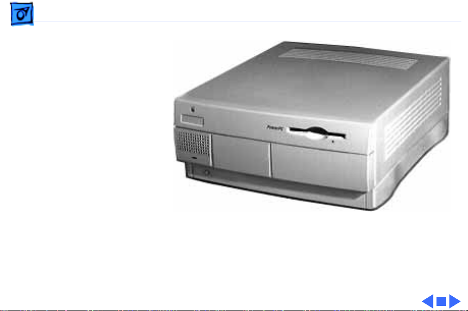
Basics Overview - 4
Power Macintosh 7200 and WS 7250 Computer
Page 7

Basics Configurations - 5
Configurations
The Power Macintosh 7200 Series computers come standard
with
• 75, 90, or 120 MHz PowerPC 601 microprocessor
• 8 or 16 MB DRAM
• 500 MB or 1.2 GB hard drive
• AppleCD 600i CD-ROM (7200/75, 7200/90, and
7200/120) or 1200i CD-ROM (7200/120 8x-CD)
• 1 MB of VRAM soldered to the logic board
The WS 7250/120 computer comes standard with
• 120 MHz PowerPC 601 microprocessor
• 16 MB DRAM
• 1.2 GB or 2 GB hard drive
• AppleCD 600i or 1200i CD-ROM drive
• 1 MB of VRAM soldered to the logic board
Page 8

Basics PowerPC 601 Microprocessor - 6
PowerPC 601 Microprocessor
The Power Macintosh 7200 Series and WS 7250 computers
feature the PowerPC 601 RISC microprocessor. Features of
this microprocessor include
• Full RISC processor architecture
• 32-bit addressing
• 64-bit data bus
• Built-in FPU
• 32K cache for data and instructions
• Internal Memory Management Unit (MMU)
• Advanced branching techniques for improved throughput
Page 9

Basics Peripheral Component Interconnect (PCI) - 7
Peripheral Component Interconnect (PCI)
The Power Macintosh 7200 Series and WS 7250 computers
offer a Peripheral Component Interconnect (PCI) expansion
bus. Because the PCI bus is an industry standard, most
existing PCI 2.0-compliant cards (with the addition of a Mac
OS-specific software driver) will work in these computers.
PCI offers significantly higher performance than the NuBus
architecture used in previous Macintosh models. Running at
33 MHz, the PCI bus is up to three times faster than NuBus,
offering overall enhanced system performance, particularly
in the areas of video and networking.
Page 10

Basics Dual In-Line Memory Modules (DIMMs) - 8
Dual In-Line Memory Modules (DIMMs)
The Power Macintosh 7200 Series and WS 7250 computers
use DRAM Dual In-Line Memory Modules (DIMMs) instead
of DRAM SIMMs. Whereas SIMMs have 72 pins, DIMMs have
168 pins. The extra pins provide a 64-bit data path,
compared to a 32-bit data path for SIMMs. In addition,
DIMMs do not have to be installed in pairs like the SIMMs on
earlier Macintosh models.
Important:
Modules (SIMMs) used in previous Macintosh models are
not
compatible with the Power Macintosh 7200 Series and
WS 7250 computers.
The VRAM and DRAM Single In-Line Memory
Page 11

Basics Memory Configurations - 9
Memory Configurations
The Power Macintosh 7200 and WS 7250 logic boards have
four DRAM DIMM slots, each with a 64-bit data bus. You can
increase the computer’s DRAM to a total of 256 MB using 5volt, 64-bit-wide, 168-pin fast-paged mode, 70 ns
DIMMs.
Note:
These computers do not have any main memory
soldered to the logic board. At least one DRAM DIMM must be
present for the computer to operate.
DRAM DIMMs can be installed individually or in pairs. These
computers support linear memory only; therefore, no
memory gains are seen when two DIMMs of the same size are
installed (that is, memory interleaving is not supported on
the Power Macintosh 7200 Series/WS 7250 computers).
Page 12
Basics Memory Configurations - 10
Note: DIMMs purchased from different manufacturers can
be paired; However, Apple recommends that you use DIMMs
of the same size and speed.
The drawing on the next page illustrates where the DRAM
slots are located on the Power Macintosh 7200 Series/WS
7250 logic boards and how they are numbered. DRAM can be
installed in any order.
Page 13
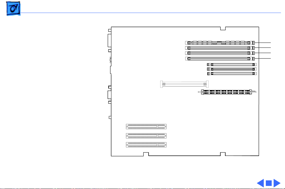
Basics Memory Configurations - 11
4
3
2
1
Figure: DRAM DIMM Slots
Page 14

Basics Ethernet Support - 12
Ethernet Support
There are two Ethernet ports on the Power Macintosh 7200
Series and WS 7250 logic boards: an AAUI port and a
10BASE-T port. You can use only one Ethernet port at one
time, however. If you have cables plugged into both Ethernet
ports, the computer uses the 10BASE-T port by default.
GeoPort
Geoport is a hardware and software communications
architecture that has been optimized for computertelephony integration. It has three main attributes:
• It lets any computer connect to any telephone (analog or
digital, public or private) anywhere in the world.
Page 15

Basics GeoPort - 13
• Once connected, it supports an arbitrary number of
independent data streams up to a total bandwidth of 2 MB/
second.
• Unlike traditional asynchronous data communications
(such as AppleTalk), GeoPort also supports isochronous
data streams (such as real-time voice and video) and
provides the real-time Application Program Interfaces
(APIs) necessary to hide the implementation details
from both the recipient and the sender.
By attaching an Apple GeoPort Telecom Adapter to the Power
Macintosh 7200 or WS 7250, you can enjoy all the features
of a 14.4 modem, including data, fax, send and receive, and
voice capabilities. The GeoPort Telecom Adapter serves as a
line interface to standard (analog) telephone lines. The
adapter is capable of sending or receiving data at up to 14.4
kbps and faxes at up to 9600 bps using the GeoPort Telecom
Adapter software.
Page 16

Basics PC Compatibility Cards - 14
PC Compatibility Cards
The Power Macintosh 7200/120 features an optional PC
Compatibility card, which brings full DOS functionality to
the Macintosh computer. Two versions of the PC
Compatibility card are available: a 7" card and a 12" card.
The cards plug into any available PCI slot on the logic board.
The two PC Compatibility cards are also available in
individual upgrade kits. Refer to the Upgrades chapter in
this manual for installation instructions.
Page 17

Basics The Cuda Chip - 15
The Cuda Chip
The Cuda is a microcontroller chip. Its function is to
• Turn system power on and off
• Manage system resets from various commands
• Maintain parameter RAM (PRAM)
• Manage the Apple Desktop Bus (ADB)
• Manage the real-time clock
Many system problems can be resolved by resetting the Cuda
chip (see Symptom Charts for examples). Press the Cuda
reset button on the logic board to reset the Cuda chip. (See
"Logic Board Diagram" later in this chapter to locate the
Cuda reset button.) If you continue to experience system
problems, refer to "Resetting the Logic Board" later in this
Basics chapter.
Page 18

Basics Resetting the Logic Board - 16
Resetting the Logic Board
Resetting the logic board can resolve many system problems
(refer to "Symptom Charts" for examples). Whenever you
have a unit that fails to power up, you should follow this
procedure before replacing any modules.
1 Unplug the computer.
2 Remove the battery from the logic board. (See Take
Apart for instructions on how to remove the battery.)
3 Disconnect the power supply cable from the logic board
and then press the Power On button. (See "Logic Board
Diagram" later in this chapter to locate the Power On
button.)
4 Wait at least 10 minutes before replacing the battery.
Make sure the battery is installed in the correct +/direction.
Page 19

Basics Resetting the Logic Board - 17
5 Reassemble the computer and test the unit.
Note:
This procedure resets the computer’s PRAM. Be sure
to check the computer’s time/date and other system
parameter settings afterwards.
Note:
If this procedure resolves the problem, claim an
adjustment on an SRO. If not, replace the defective
component and DO NOT claim the adjustment procedure.
Page 20

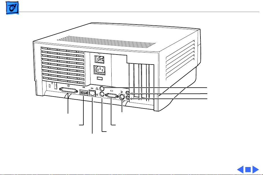
Basics Rear View Diagram - 18
Rear View Diagram
The Power Macintosh 7200 Series and WS 7250 computers
offer the following external ports: SCSI, AAUI Ethernet,
10BASE-T Ethernet, serial printer (GeoPort compatible),
serial modem (GeoPort compatible), DB-15 video, ADB,
sound input, and sound output.
The drawing on the next page illustrates the external ports
on the Power Macintosh 7200 Series and WS 7250
computers.
Page 21
Basics Rear View Diagram - 19
Printer
Sound Out
Sound In
SCSI
AAUI
Ethernet
10BASE-T
ADB
Monitor
Modem
Ethernet
Figure: Power Macintosh 7200 and WS 7250 Rear Panel
Page 22

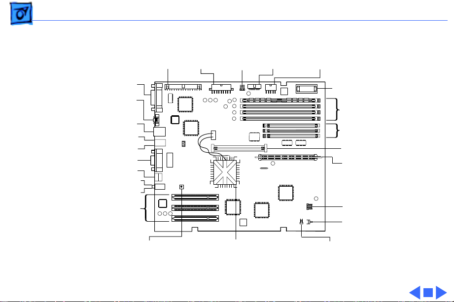
Basics Power Macintosh 7200 Logic Board Diagram - 20
Power Macintosh 7200 Logic Board Diagram
There are five versions of the Power Macintosh 7200 logic
board: one 75 MHz version, two 90 MHz versions, and two
120 MHz versions. The two 90 MHz versions of the logic
board are functionally equivalent, as are the two 120 MHz
versions; However, one of the 90 MHz versions and one of
the 120 MHz versions has an auxiliary fan that connects at
J70.
Important
and one black wire) that runs from the processor to the logic
board or you will damage the board.
The following drawing shows the Power Macintosh 7200
logic board. Refer to the parts chapter for information on
how you can distinguish between the different logic boards.
: Do not unplug the Peltier device (one red wire
Page 23
Basics Power Macintosh 7200 Logic Board Diagram - 21
External SCSI
AAUI Ethernet
10BASE-T
Ethernet
Modem (bottom)
Printer (top)
Sound Out (top)
Sound In (bottom)
PCI Slots
Internal
SCSI
Power
Supply
CD
Audio
Floppy
Drive
3.3V Power
Video
ADB
Cuda Reset
PowerPC 601 Processor Speaker
Figure: Power Macintosh 7200 Logic Board
Supply
4
3
2
1
3
2
1
Battery
DRAM Slots
VRAM Slots
Cache DIMM
ROM SIMM
Power LED
Power
On/Off
Page 24

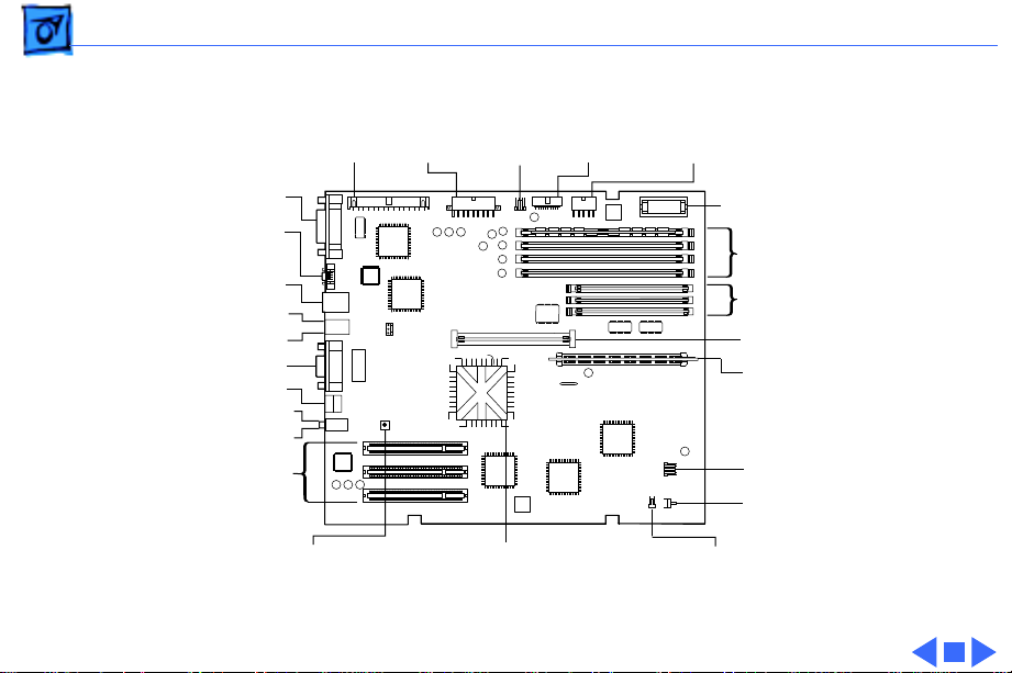
Basics Workgroup Server 7250 Logic Board Diagram - 22
Workgroup Server 7250 Logic Board Diagram
There is only one version of the WS 7250 logic board, which
features a 120 MHz microprocessor. This board does not
require an auxiliary processor fan.
The following drawing shows the WS 7250 logic board.
Some versions of the logic board have a ROM SIMM while
others have the ROM soldered on the logic board.
Note:
Page 25
Basics Workgroup Server 7250 Logic Board Diagram - 23
External SCSI
AAUI Ethernet
10BASE-T
Ethernet
Modem (bottom)
Printer (top)
Video
ADB
Sound Out (top)
Sound In (bottom)
PCI Slots
Cuda Reset
Internal
SCSI
Power
Supply
CD
Audio
Floppy
Drive
3.3V Power
Supply
4
3
2
1
3
2
1
PowerPC 601 Processor Speaker
Figure: Workgroup Server 7250 Logic Board
Battery
DRAM Slots
VRAM Slots
Cache DIMM
ROM SIMM
Power LED
Power
On/Off
Page 26

Basics Repair Strategy - 24
Repair Strategy
Service the Power Macintosh 7200 Series and WS 7250
computers through module exchange and parts replacement.
Customers can request on-site service from an Apple
Authorized Service Provider Plus (AASP+) or Apple
Assurance. They can also choose carry-in service from an
AASP.
Ordering
Apple Service Providers planning to support the Power
Macintosh 7200 Series and WS 7250 computers may
purchase Service modules and parts to develop servicing
capability. To order parts, use the AppleOrder system and
refer to the Power Macintosh 7200 or Workgroup Server
7250 "Service Price Pages."
Page 27

Basics Ordering - 25
Large businesses, universities, and K-12 accounts must
provide a purchase order on all transactions, including
orders placed through the AppleOrder system. Service
providers not enrolled in AppleOrder may fax their orders
to Service Provider Support (512-908-8125) or mail
them to
Apple Computer, Inc.
Service Provider Support
MS 212-SPS
Austin, TX 78714-9125
If you have further questions, please call Service Provider
Support at 800-919-2775 and select option #1.
Page 28

Basics Warranty and AppleCare - 26
Warranty and AppleCare
The Power Macintosh 7200 Series and WS 7250 computers
are covered under the Apple One-Year Limited Warranty.
The AppleCare Service Plan is also available for these
products. Service Providers are reimbursed for warranty
and AppleCare repairs made to these computers. For pricing
information, refer to "Service Price Pages."
Page 29
K
Service Source
Specifications
Power Macintosh 7200 Series/
WS 7250
Page 30

Specifications Processor - 1
Processor
CPU
PM 7200/75 and 7200/90
PM 7200/120 and WS 7250/120
PowerPC 601 RISC microprocessor running at 75 or 90 MHz
Built-in FPU and 32K cache
Requires system software version 7.5.2 or later with appropriate
System Enabler
PowerPC 601 RISC microprocessor running at 120 MHz
Built-in FPU and 32K cache
Requires system software version 7.5.3 or later with appropriate
System Enabler
Note: the 8x CD configurations of the Power Macintosh 7200/
120 and 7250/120 require system software 7.5.3 Revision 2.
Page 31

Specifications Memory - 2
Memory
DRAM
ROM
Cache
Clock/Calendar
8 MB or 16 MB standard; expandable to 256 MB
Uses 168-pin, 64-bit, 70 ns or faster DRAM DIMMs
4 MB ROM (may be installed in ROM SIMM slot, or soldered on the
logic board)
Supports 256K Level 2 cache DIMM
CMOS custom circuitry with long-life battery
Page 32

Specifications I/O Interfaces - 3
I/O Interfaces
SCSI
Serial
ADB
Ethernet
Dual-channel asynchronous SCSI interface; external channel
supports up to seven SCSI devices
Two RS-232/RS-422 serial ports compatible with LocalTalk and
GeoPort cables; mini DIN-8 connectors
One Apple Desktop Bus port for a keyboard, mouse, etc.
One AAUI and one 10BASE-T Ethernet port (if cables are plugged
into both ports, system defaults to 10BASE-T)
Page 33

Specifications I/O Interfaces - 4
Expansion
Sound
Video
Three PCI expansion slots, compatible with all PCI 2.0
specification-compliant cards with the addition of a Mac OSspecific software driver (not NuBus compatible)
16-bit stereo sound input and output ports
Built-in DB-15 video connector on logic board
Page 34

Specifications I/O Devices - 5
I/O Devices
Keyboard
Mouse
Microphone
PM 7200 Series
Standard, extended, or adjustable keyboard; keyboard draws
25-80 mA, depending on model type
ADB Mouse II; mouse draws up to 10 mA
Apple PlainTalk microphone standard
Page 35

Specifications Video Support - 6
Video Support
Table 1: Video Table for Power Macintosh 7200 Series/WS 7250
PIXEL DEPTHS
MONITOR DISPLAY SIZE 1 MB VRAM* 2 MB VRAM* 4 MB VRAM*
512 by 384 8,16,32 8,16,32 8,16,32
640 by 480 8,16 8,16,32 8,16,32
768 by 576 8,16 8,16,32 8,16,32
800 by 600 8,16 8,16,32 8,16,32
832 by 624 8,16 8,16,32 8,16,32
1024 by 768 8 8,16 8,16,32
1280 by 960 _ 8 8,16
1280 by 1024 _ 8 8,16
*
VRAM expansion works as follows:1 MB of VRAM is soldered to
the board. To go to 2 MB, install one 1 MB VRAM DIMM in slot 1.
To go to 4 MB, install three 1MB VRAM DIMMs in slots 1, 2, & 3.
Page 36

Specifications Disk Storage - 7
Disk Storage
Hard Drive
PM 7200/75 and 7200/90
PM 7200/120
WS 7250/120
Floppy Drive
CD-ROM Drive
500 MB internal SCSI hard drive
1.2 GB internal SCSI hard drive
2 GB internal SCSI hard drive
One Apple SuperDrive 1.4 MB floppy drive
One internal AppleCD 600i 4x CD-ROM drive or
1200i 8x CD-ROM drive
Page 37

Specifications PC Compatibility Card (Optional) - 8
PC Compatibility Card (Optional)
Processor
7" Card 12" Card
DRAM
7" Card 12" Card
VRAM
7" Card 12" Card
5x86 processor operating at 100 MHz
Pentium processor operating at 100 MHz
8 MB DIMM standard, expandable to 64 MB
8 MB built-in, expandable to 72 MB
1 MB
1 MB, expandable to 2 MB
Page 38

Specifications PC Compatibility Card (Optional) - 9
Cache
7" Card 12" Card
Sound
Software
Networking
128K Level 2 cache
256 K Level 2 Cache
Sound Blaster 16-compatible support
MS-DOS version 6.22 included
Support for Novell NetWare SPX/IPX, TCP/IP, and NETBEUI
protocols in MS-DOS and Windows environments using the
built-in Ethernet connector and an ODI driver (network client
software not included)
Page 39

Specifications Electrical - 10
Electrical
Line V oltage
PM 7200
WS 7250/120
Frequency
Maximum Power
100-240 VAC, RMS single phase, automatically configured
100-270 VAC, RMS single phase, automatically configured
50-60 Hz, single phase
150 W maximum, not including monitor
Note
: the power supply has two voltage settings: 115V and
230 V. The power supply must be set to 115V in the U.S.
Page 40

Specifications Physical - 11
Physical
Dimensions
Height
Width
Depth
Weight
6.5 in. (15.6 cm)
14.37 in. (36.5 cm)
16.93 in. (43.0 cm)
22 lb. (9.97 kg); weight varies depending on devices installed
Page 41

Specifications Environmental - 12
Environmental
Operating Temperature
Storage Temperature
50 to 104° F (10 to 40° C)
—40 to 116° F (—40 to 47° C)
Relative Humidity
Maximum Altitude
5% to 95% noncondensing
10,000 ft. (3,048 m)
Page 42

K
Service Source
Troubleshooting
Power Macintosh 7200 Series/
WS 7250
Page 43

Troubleshooting General - 1
General
The Symptom Charts included in this chapter will help you
diagnose specific symptoms related to your product. Because cures
are listed on the charts in the order of most likely solution, try
the first cure first. Verify whether or not the product continues to
exhibit the symptom. If the symptom persists, try the next cure.
(Note: If you have replaced a module, reinstall the original module
before you proceed to the next cure.)
If you are not sure what the problem is, or if the Symptom Charts
do not resolve the problem, refer to the Flowchart for the product
family.
For additional assistance, contact Apple Technical Support.
Page 44

Troubleshooting Cleaning Procedure for Card Connectors - 2
Cleaning Procedure for Card Connectors
It is possible for residue to build up on the gold edge connector
pins on some PCI cards, which could cause a variety of symptoms.
If you are having problems with a PCI card, inspect the connector
pins with a magnifying glass. If you find residue, use a pencil
eraser to gently clean the pins.
Page 45

Troubleshooting Symptom Charts/Power Supply - 3
Symptom Charts
Power Supply
System doesn’t power up1 Reseat ROM SIMM (if present).
2 Reset Cuda chip. (Refer to The Cuda Chip in Basics for
instructions.)
3 Reset logic board. (Refer to Resetting the Logic Board in
Basics for instructions.)
4 Replace power supply.
5 Replace logic board.
Page 46

Troubleshooting Symptom Charts/Error Chords - 4
Error Chords
One-part error
chord sounds during
startup sequence
Eight-part error
chord (death chimes)
sounds during
startup sequence
1 Disconnect SCSI data cable from hard drive and reboot
system. If startup sequence is normal, initialize hard drive.
Test unit again with SCSI data cable connected. If error chord
still sounds, replace hard drive.
2 Disconnect floppy drive cable from floppy drive and reboot
system. If startup sequence is normal, replace floppy drive.
3 Replace logic board. Retain customer's DIMMs.
1 Replace DRAM DIMMs one at a time to test DRAM. Replace
any faulty DIMMs.
2 Replace logic board.
Page 47

Troubleshooting Symptom Charts/System - 5
System
Does not power on,
screen is black, fan is
not running and LED
is not lit
1 Check power cables.
2 Plug monitor directly into wall socket, and verify that
monitor has power.
3 Reseat ROM SIMM (if present).
4 Reset Cuda chip. (Refer to The Cuda Chip in Basics for
instructions.)
5 Reset logic board. (Refer to Resetting the Logic Board in
Basics for instructions.)
6 Replace power cord.
7 Replace power supply.
8 Replace logic board. Retain customer's DIMMs.
Page 48

Troubleshooting Symptom Charts/System - 6
Clicking, chirping,
or thumping
1 Remove all PCI cards and test the unit. If problem does not
occur with cards removed, begin replacing them one at a
time to determine which card is causing the problem.
Replace problem card with known-good card.
2 Remove hard drive. If problem no longer occurs, replace
hard drive with a known-good drive.
3 Replace power supply.
4 Replace logic board. Retain customer's DIMMs.
5 Replace floppy drive cable.
6 Replace floppy drive.
Page 49

Troubleshooting Symptom Charts/System - 7
System shuts down
intermittently
1 Make sure air vents are clear. Thermal protection
circuitry may shut down system. After 30 to 40 minutes,
system should be OK.
2 Make sure power cord is firmly plugged in.
3 Verify fan is plugged in and working (if present). Replace if
necessary. (Note: Some 90 MHz versions of the Power
Macintosh 7200 logic board have a fan that plugs into the
logic board near the processor.)
4 Replace power cord.
5 Check battery.
6 Reset Cuda chip. (Refer to The Cuda Chip in Basics for
instructions.)
7 Reset logic board. (Refer to Resetting the Logic Board in
Basics for instructions.)
8 Replace power supply.
9 Replace logic board. Retain customer's DIMMs.
Page 50

Troubleshooting Symptom Charts/System - 8
System
intermittently
crashes or hangs
1 Verify system software is version 7.5.2 or later (Power
Macintosh 7200/75 or 7200/90) or 7.5.3 or later (Power
Macintosh 7200/120 or WS 7250/120).
2 Verify DIMMs are noncomposite.
3 Verify software is known-good. Do a clean install of the
system software.
4 Verify software is Power Macintosh 7200/WS 7250
compatible (contact developer). Also, try booting with
extensions off to determine if there are system init problems.
5 Clear parameter RAM. Hold down <Command> <Option> <P>
<R> during startup but before "Welcome to Macintosh"
appears.
6 Remove all DRAM DIMMs and try replacing them one at a
time to test. Replace any bad DIMMs.
7 Replace logic board. Retain DIMMs.
Page 51

Troubleshooting Symptom Charts/System - 9
During startup,
following message is
displayed, "This
startup disk will not
work on this
Macintosh model...."
System can’t be
powered off unless
external 1.2 GB hard
drive is off
remains lit when
system is powered off
and attached 1.2 GB
hard drive is left
powered on
or
LED
1 Verify that startup disk is good.
2 Verify system software is version 7.5.2 or later (Power
Macintosh 7200/75 or 7200/90) or 7.5.3 or later (Power
Macintosh 7200/120 or WS 7250/120).
3 Do a clean install of the system software.
This problem only affects PM 7200 and WS 7250 machines with
serial numbers in the following ranges:
• CK634xxxxxx to CK637xxxxxx
• XB634xxxxxx to XB637xxxxxx
• SG634xxxxxx to SG637xxxxxx
• FC634xxxxxxx to FC637xxxxxx
If system falls into one of these serial number ranges, execute
the following instructions:
1) Unplug system and remove top cover.
Page 52

Troubleshooting Symptom Charts/System - 10
2) Disconnect hard drive SCSI cable and power cable.
3) Remove hard drive from chassis.
4) Turn drive over and examine part number label on 50-pin
SCSI connector (removing drive carrier if necessary). If
label reads “1280S p/n TM12S012”
replace drive.
Note
: Only Revision “02” drives cause this problem; therefore, make sure bar code label includes the words “REV 02B” before replacing hard drive.
and
“REV 02-B”,
Page 53

Troubleshooting Symptom Charts/Video - 11
Video
Screen is black, boot
tone is present, drive
operates, fan is
running, and LED is
lit
1 Adjust brightness on monitor.
2 Clear parameter RAM. Hold down <Command> <Option> <P>
<R> during startup but before "Welcome to Macintosh"
appears.
3 Reset Cuda chip. (Refer to The Cuda Chip in Basics for
instructions.)
4 Reset logic board. (Refer to Resetting the Logic Board in
Basics for instructions.)
5 Replace monitor cable.
6 Remove all DRAM DIMMs and try replacing them one at a
time to test. Replace any bad DIMMs.
7 Test with known-good monitor. Replace monitor if
necessary. Refer to appropriate monitor manual to
troubleshoot defective monitor.
8 Replace logic board. Retain customer's DIMMs.
Page 54

Troubleshooting Symptom Charts/Video - 12
Screen is black, no
boot tone and drive
does not operate, but
fan is running and
LED is lit
1 Reset Cuda chip. (Refer to The Cuda Chip in Basics for
instructions.)
2 Reset logic board. (Refer to Resetting the Logic Board in
Basics for instructions.)
3 Remove all DRAM DIMMs and try replacing them one at a
time to test. Replace any bad DIMMs.
4 Replace logic board. Retain customer's DIMMs.
5 Replace power supply.
Page 55

Troubleshooting Symptom Charts/Video - 13
Boot tone is present
and screen lights up,
but nothing is
displayed on screen
1 Reset Cuda chip. (Refer to The Cuda Chip in Basics for
instructions.)
2 Reset logic board. (Refer to Resetting the Logic Board in
Basics for instructions.)
3 Replace monitor cable.
4 Test with known-good monitor. Replace monitor if
necessary. Refer to appropriate monitor manual to
troubleshoot defective monitor.
5 Replace logic board. Retain customer's DIMMs.
Page 56

Troubleshooting Symptom Charts/ Floppy Drive - 14
Floppy Drive
Internal floppy drive
does not operate
During system
startup, disk ejects;
display shows icon
with blinking “X”
1 Replace floppy disk with known-good disk.
2 Replace floppy drive cable.
3 Replace floppy drive.
4 Replace logic board. Retain customer's DIMMs.
1 Replace disk with known-good system disk.
2 Replace floppy drive cable.
3 Replace floppy drive.
4 Replace logic board. Retain customer's DIMMs.
Page 57

Troubleshooting Symptom Charts/ Floppy Drive - 15
Does not eject disk 1 Shut down computer. Hold mouse button down while you
restart computer.
2 Replace floppy drive cable.
3 Replace floppy drive.
4 Replace logic board. Retain customer's DIMMs.
Attempts to eject
disk, but doesn’t
1 Reseat floppy drive bezel and drive so bezel slot aligns
correctly with drive.
2 Replace floppy drive.
Page 58

Troubleshooting Symptom Charts/Floppy Drive - 16
MS-DOS drive does
not recognize a disk
formatted on a 1.4 MB
drive
Internal floppy drive
runs continuously
To read and write files with either MS-DOS or 1.4 MB drive,
format all disks with MS-DOS drive first.
1 Replace disk with known-good floppy disk.
2 Replace floppy drive cable.
3 Replace floppy drive.
4 Replace logic board. Retain customer's DIMMs.
Page 59

Troubleshooting Symptom Charts/Hard Drive - 17
Hard Drive
Single internal hard
drive does not
operate; drive
doesn’t spin
No internal SCSI
drives operate
1 Replace hard drive. If problem resolved, reinstall SCSI
device driver and system software.
2 Replace power supply.
1 Verify there are no duplicate SCSI device addresses.
2 Disconnect external SCSI devices and check for proper
termination. Only last device in SCSI chain should be
terminated.
3 Replace SCSI data cable.
4 Replace power supply.
5 Replace logic board. Retain customer's DIMMs.
Page 60

Troubleshooting Symptom Charts/Peripherals - 18
Drive does not appear
on the desktop
Works with internal
or external SCSI
devices but not with
both
1 Verify there are no duplicate SCSI device addresses.
2 Update SCSI device driver using Drive Setup. Check drive’s
directory structure using Disk First Aid.
3 Replace SCSI hard drive cable.
4 If drive is not initialized, use Drive Setup to initialize.
5 Replace with known-good hard drive.
6 If hard drive still doesn't work, switch back to original hard
drive and replace logic board.
1 Verify there are no duplicate SCSI device addresses.
2 Replace terminator on external SCSI device.
3 Verify that SCSI device at end of internal SCSI data cable is
only device terminated.
4 Refer to appropriate manual to troubleshoot defective
external device.
Page 61

Troubleshooting Symptom Charts/Peripherals - 19
Peripherals
Cursor does not move 1 Check mouse connection.
2 Inspect inside of mouse for buildup of dirt or other
contaminants. Clean mouse if necessary.
3 If mouse was connected to keyboard, connect mouse to
computer ADB port instead. If mouse works, replace
keyboard.
4 Replace ADB cable.
5 If mouse does not work in any ADB port on computer, replace
mouse.
6 Replace logic board. Retain customer's DIMMs.
Cursor moves, but
clicking mouse
button has no effect
1 Boot from floppy or bootable CD.
2 Replace mouse.
3 Replace logic board. Retain customer's DIMMs.
Page 62

Troubleshooting Symptom Charts/Peripherals - 20
Double-click doesn’t
open application,
disk, or server
No response to any
key on keyboard
1 Remove duplicate system folders.
2 Clear parameter RAM. Hold down <Command> <Option> <P>
<R> during startup but before "Welcome to Macintosh"
appears.
3 If mouse was connected to keyboard, connect mouse to
computer ADB port instead. If mouse works, replace
keyboard.
4 If mouse does not work in any ADB port on computer, replace
mouse.
5 Replace logic board. Retain customer's DIMMs.
1 Check keyboard connection to ADB port.
2 Replace keyboard cable.
3 Replace keyboard.
4 Replace logic board. Retain customer's DIMMs.
Page 63

Troubleshooting Symptom Charts/Peripherals - 21
Known-good serial
printer does not work
Known-good network
printer does not print
1 Verify you have correct version of system software.
2 Verify that Chooser is set correctly.
3 Reinstall correct printer drivers.
4 Do clean install of system software.
5 Replace printer interface cable.
6 Replace logic board. Retain customer's DIMMs.
1 Check network connections.
2 Verify you have correct version of system software.
3 Verify that Chooser is set correctly.
4 Does printer show up in Chooser? If so, do clean install of
system software and/or network and printer software.
5 Replace logic board. Retain customer's DIMMs.
Page 64

Troubleshooting Symptom Charts/CD-ROM Drive - 22
CD-ROM Drive
CD-ROM drive does
not work
Macintosh does not
display CD-ROM icon
once CD is inserted in
drive
Computer with 600i
CD-ROM drive makes
stuttering sounds
when playing CD+ or
CD-R formatted
discs or CD-ROM disc
won’t mount
1 Try using known-good compact disc.
2 Replace CD-ROM drive mechanism.
1 Verify that CD-ROM software is installed.
2 Replace CD-ROM drive mechanism.
3 Replace SCSI data cable.
Replace CD-ROM drive.
Page 65

Troubleshooting Symptom Charts/Miscellaneous - 23
Miscellaneous
No sound from
speaker
1 Verify that volume setting in Control Panel is 1 or above.
2 Clear parameter RAM. Hold down <Command> <Option> <P>
<R> during startup but before “Welcome to Macintosh”
appears.
3 Verify speaker is plugged into logic board.
4 Replace speaker.
5 Replace logic board. Retain customer’s DIMMs.
Page 66

Troubleshooting Symptom Charts/Miscellaneous - 24
Transferring/printing large files across
certain repeaters
causes Power
Macintosh 7200/90
to hang or exhibit
poor performance or
Power Macintosh
7200/90 locks up or
times out when running under TCP
1 Verify computer is Power Macintosh 7200/90 and attached
to Ethernet network.
2 Test to see if problem occurs on other systems (preferably
Power Macintosh 7200/75, 7500, 8500, or 9500
computers that utilize the new Open Transport networking
protocol).
• If yes, difficulty may be related to software or network to
which computer is attached. Perform basic software and
network troubleshooting to pinpoint problem.
• If no, difficulty may be related to Ethernet clock jitter.
Refer to logic board identification instructions on next
page to determine whether or not logic board has been
revised. If logic board is a revised module, problem may
have to do with the network. If logic board has not been
revised, replace it in at least one of the systems to verify
whether a revised board solves the problem.
Page 67

Troubleshooting Symptom Charts/Miscellaneous - 25
Identifying Logic Boards
As a general rule, if the Power Macintosh 7200/90 computer has
a serial number of xx545xxxxxx or higher, then the computer
should have the revised logic board already installed. If the
computer has a serial number of xx544xxxxxx, xx543xxxxxx or
below, verify that the board is revised as follows:
Look at location G1; G1 is located next to the internal 50-pin SCSI
connector and the CURIO ASIC.
• If a 20 MHz oscillator is present at location G1, the logic
board has been revised.
• If a 20 MHz oscillator is not present (four blank solder
pads) then the board has not been revised and should be
replaced under warranty.
Page 68

K
Service Source
T ak e Apart
Power Macintosh 7200 Series/
WS 7250
Page 69

Take Apart Top Housing - 1
Top Housing
Top Housing
No preliminary steps are
required before you begin
this procedure.
Note:
The top housing covers
the top, front, and left and
right sides of the computer.
Page 70

Take Apart Top Housing - 2
1 Press the two tabs at the
front corners of the top
housing to release the
top housing from the
bottom chassis.
Left
Tab
Right
Tab
Page 71

Take Apart Top Housing - 3
2 Pull the top housing
forward about 1 to 2
inches and lift straight
up to remove the top
housing from the
computer.
Page 72

Take Apart Bezels - 4
Bezels
Before you begin, remove
the top housing.
Note:
As you face the
computer, the bezels are in
the middle of the top
housing’s front panel.
Blank Bezel
CD-ROM Bezel
Page 73

Take Apart Bezels - 5
Tab
1 From the inside of the
top housing, push out on
the moon-shaped
opening at the bottom of
the bezel to release the
tab. Lift up the bezel to
remove it from the top
housing.
Page 74

Take Apart CD-ROM Drive - 6
CD-ROM Drive
Before you begin, remove
the top housing.
Note:
As you face the
computer, the CD-ROM
drive is in the bottom right
drive bay.
CD-ROM Drive
Page 75

Take Apart CD-ROM Drive - 7
1 Lift up the top tabs and
pull out the CD-ROM
EMI shield to remove it
from the front of the
CD-ROM drive.
CD-ROM Shield
Page 76

Take Apart CD-ROM Drive - 8
2 Disconnect the SCSI
cable, power cable, and
CD audio cable from the
back of the CD-ROM
drive.
CD Audio CableSCSI CablePower Cable
Page 77

Take Apart CD-ROM Drive - 9
3 Pull up the retaining
clip (which is located at
the back of the CD-ROM
drive) and slide the CDROM forward to remove
it from the internal
chassis.
Note:
Be sure to remove the
CD-ROM drive from its
carrier before returning the
drive to Apple.
CD-ROM Drive
Page 78

Take Apart Floppy Drive - 10
Floppy Drive
Before you begin, remove
the top housing.
Note:
As you face the
computer, the floppy drive
is in the top right drive bay.
Floppy Drive
Page 79

Take Apart Floppy Drive - 11
1 Remove the CD-ROM
shield, the blank shield,
and the floppy drive
shield from the front of
the unit.
Floppy Drive Shield
Blank Shield
CD-ROM Shield
Page 80

Take Apart Floppy Drive - 12
Chassis Support Foot
2 Flip open the chassis
support foot.
Page 81

Take Apart Floppy Drive - 13
Floppy Drive Cable Floppy Drive
3 Disconnect the floppy
drive cable from the
back of the floppy drive.
Page 82

Take Apart Floppy Drive - 14
Drive Rails Floppy Drive
4 Pull out on the plastic
drive rails that hold the
floppy drive to the drive
chassis and push the
drive back to release it.
Replacement Note:
If you
are replacing the floppy
drive, remove the EMI
gasket from the defective
drive and attach the gasket
in the center of the replacement drive’s top surface,
with the “V” of the gasket
pointing at the front edge of
the drive. If the old gasket
won't stick, order a new
gasket (p/n 922-1895).
Page 83

Take Apart Hard Drive - 15
Hard Drive
Before you begin, remove
the top housing.
Note:
As you face the
computer, the hard drive is
in the top left drive bay.
Hard Drive
Page 84

Take Apart Hard Drive - 16
1 Remove the CD-ROM
shield, the blank shield,
and the floppy drive
shield from the front of
the unit.
Floppy Drive Shield
Blank Shield
CD-ROM Shield
Page 85

Take Apart Hard Drive - 17
2 Disconnect the SCSI
cable and hard drive
Power Cable
power cable from the
back of the hard drive.
SCSI Cable
Page 86

Take Apart Hard Drive - 18
3 Pull up the retaining
clip at the back of the
Retaining Clip
hard drive and push back
the hard drive to
remove it from the drive
chassis.
Note:
For information on
removing the hard drive
from its carrier and
returning drives, cables,
and carriers to Apple, refer
to Additional Procedures in
the Hard Drives manual.
Hard Drive
Page 87

Take Apart Chassis Latch - 19
Chassis Latch
Chassis Latch
Chassis Latch
Before you begin, remove
the top housing.
Note:
The chassis latches
mount in the internal
chassis and secure the
internal chassis to the
external chassis frame.
Page 88

Take Apart Chassis Latch - 20
1 Use a screwdriver to
push out the tab
indicated in the
illustration. Slide the
latch forward and lift it
from the chassis.
Tab
Page 89

Take Apart Drive Rails - 21
Drive Rails
Before you begin, remove:
• Top Housing
• All Drives
Note:
The drive rails attach
to the internal chassis
underneath the CD-ROM
drive and the extra hard
drive bay.
Drive Rails
Page 90

Take Apart Drive Rails - 22
1 First, release the
chassis latches. Next,
flip open the chassis
support foot and then
swing open the internal
chassis that contains the
power supply.
IMPORTANT:
On some 90 and
120 MHz versions there is a
fan that plugs into the logic
board at connector J70. You
must unplug the fan as you
are swinging open the
chassis. Be sure to plug the
Chassis Support FootInternal Chassis
fan back in when you put the
unit back together.
Page 91

Take Apart Drive Rails - 23
Tab
2 Use a screwdriver to
push out the tab
indicated in the
illustration.
3 Slide the drive rail
either forward or
backward (depending on
which way the tabs are
facing) and lift it from
the chassis.
IMPORTANT:
On some 90
and 120 MHz versions
there is a fan that plugs into
the logic board at connector
J70. Be sure to plug the fan
back in when you put the
unit back together.
Page 92

Take Apart Battery - 24
Battery
Before you begin, remove
the top housing.
Note:
As you face the
computer, the battery is
near the front left corner of
the logic board.
Battery
Page 93

Take Apart Battery - 25
1 First, release the
chassis latches. Next,
flip open the chassis
support foot and then
swing open the internal
chassis that contains the
power supply.
IMPORTANT
: On some 90 and
120 MHz versions there is a
fan that plugs into the logic
board at connector J70. You
must unplug the fan as you
are swinging open the
chassis. Be sure to plug the
Chassis Support FootInternal Chassis
fan back in when you put the
unit back together.
Page 94

Take Apart Battery - 26
2 Use a screwdriver to
gently pry up one side of
the battery cover.
Page 95

Take Apart Battery - 27
3 Lift up the battery to
remove it from the logic
board.
IMPORTANT
120 MHz versions there is a
fan that plugs into the logic
board at connector J70. Be
sure to plug the fan back in
when you put the unit back
together.
: On some 90 and
Page 96

Take Apart Power Supply - 28
Power Supply
Power Supply
Before you begin, remove
the top housing.
Note:
As you face the
computer, the power supply
is in the back right corner.
IMPORTANT
replacing the power supply,
be sure the voltage switch on
the back of the power supply
is set correctly (115V in
the U.S.).
: When
Page 97

Take Apart Power Supply - 29
CD Power CableHard Drive Power Cable
1 Disconnect the power
supply cables from the
back of the CD-ROM
drive and hard drive(s).
Page 98

Take Apart Power Supply - 30
2 First, release the
chassis latches. Next,
flip open the chassis
support foot and then
swing open the internal
chassis that contains the
power supply.
IMPORTANT
: On some 90 and
120 MHz versions there is a
fan that plugs into the logic
board at connector J70. You
must unplug the fan as you
are swinging open the
chassis. Be sure to plug the
Chassis Support FootInternal Chassis
fan back in when you put the
unit back together.
Page 99

Take Apart Power Supply - 31
3 To secure the internal
chassis in the up
position, flip down the
chassis support arm.
Make sure the tab on the
bottom of the support
arm is securely fastened
Chassis
Support Arm
in the hole provided in
the bottom chassis.
Tab
Warning
: To be safe, never
work on the computer with
the internal chassis in the
up position unless the
chassis support arm is
down and securely fastened.
Page 100

Take Apart Power Supply - 32
Power Supply Cables
4 Disconnect the power
supply cables from the
logic board.
Note:
The 22-pin cable
supplies 5 V and +/- 12 V
power for the logic board.
 Loading...