

Page 1
K
Service Source
Power Macintosh 9500
Series
Power Macintosh 9500/120, 9500/132, 9500/150,
9500/180MP, and 9500/200
Page 2
K
Service Source
Basics
Power Macintosh 9500 Series
Page 3

Basics Overview - 1
Overview
The Power Macintosh 9500 Series computers are based on
the PowerPC 604 microprocessor and support the
industry-standard PCI (Peripheral Component
Interconnect) bus specification. These computers are the
most flexible, expandable, and highest-performance
systems from Apple to date.
The microprocessor for the Power Macintosh 9500 Series
computers is on separate plug-in card, which allows for
easy upgrades. The Power Macintosh 9500 family includes
five versions: the 9500/120, the 9500/132, the
9500/150, the 9500/180MP (multi-processor), and the
9500/200.
Page 4

Basics Overview - 2
Features of the Power Macintosh 9500 Series include
• 120, 132, 150, 180 (multi-processor) or 200 MHz
PowerPC 604 microprocessor card with built-in FPU
• Six PCI expansion slots
• 10 MB per second internal SCSI channel, 5 MB per
second external SCSI channel
• 512K Level 2 cache
• DRAM expansion up to 1536 MB using 168-pin, 70 ns,
64-bit DIMMs
• A PCI Apple Accelerated Graphics card included with
some configurations (the Power Macintosh 9500 Series
does not include on-board video support)
• Built-in AAUI and 10BASE-T Ethernet
• AppleCD™ 600i 4x or1200i 8x CD-ROM drive
• CD-quality stereo sound in/out
• Mac™ OS system software 7.5.2, 7.5.3, or 7.5.3
Revision 2
Page 5

Basics Configurations - 3
Configurations
The Power Macintosh 9500/120 comes standard with
• 120 MHz PowerPC 604 processor card
• 16 MB DRAM minimum
• 1 GB hard drive
• AppleCD 600i CD-ROM drive
• Apple Accelerated Graphics card with 2 MB of VRAM
The Power Macintosh 9500/132 comes standard with
• 132 MHz PowerPC 604 processor card
• 16 MB DRAM minimum
• 2 GB hard drive
• AppleCD 600i CD-ROM drive
Page 6

Basics Configurations - 4
The Power Macintosh 9500/150 comes standard with
• 150 MHz PowerPC 604 processor card
• 16 or 32 MB DRAM minimum
• 2 GB hard drive
• AppleCD 600i CD-ROM drive
The Power Macintosh 9500/180MP comes standard with
• 180 MHz PowerPC 604e multi-processor card
• 16 or 32 MB DRAM minimum
• 2 GB hard drive
• AppleCD 1200i 8x-speed CD-ROM drive
The Power Macintosh 9500/200 comes standard with
• 200 MHz PowerPC 604e processor card
• 16 or 32 MB DRAM minimum
• 2 GB hard drive
• AppleCD 1200i 8x-speed CD-ROM drive
Page 7

Basics PowerPC 604 Microprocessor - 5
PowerPC 604 Microprocessor
The Power Macintosh 9500 Series computers feature the
highest performance PowerPC processor available: the
PowerPC 604 RISC microprocessor. Designed to bring
unprecedented levels of performance to desktop computers,
the Power PC 604 processor offers up to 1.5 times the
performance of the PowerPC 601 processor at the same
clock speed. Features include
• Full RISC processing architecture
• Parallel processing units: one load-store unit, two
integer units, one complex integer unit, and one floating
point unit
• Separate built-in caches for data and instructions, 16
KB each, four-way set associative
• Advanced branching techniques for improved throughput
Page 8

Basics Multi-Processor Support - 6
The PowerPC 604 processor is installed via a processor
card that plugs into the Macintosh 9500 Series logic board,
allowing for maximum flexibility with future upgrades.
Multi-Processor Support
The Power Macintosh 9500/180MP features two 180 MHz
PowerPC 604e chips on its microprocessor card. This
computer provides extremely rapid performance for
applications that can take advantage of its coprocessing
capabilities.
Page 9

Basics Peripheral Component Interconnect (PCI) - 7
Peripheral Component Interconnect (PCI)
The Power Macintosh 9500 Series computers offer a
Peripheral Component Interconnect (PCI) expansion bus.
Because the PCI bus is an industry standard, most existing
PCI 2.0-compliant cards (with the addition of a Mac OSspecific software driver) will work in the Power Macintosh
9500 Series computers.
PCI offers significantly higher performance than the NuBus
architecture used in previous Macintosh models. Running at
33 MHz, the PCI bus is up to three times faster than NuBus,
offering overall enhanced system performance, particularly
in the areas of video and networking.
Page 10

Basics Dual In-Line Memory Modules (DIMMs) - 8
Dual In-Line Memory Modules (DIMMs)
The Power Macintosh 9500 Series computers use DRAM
Dual In-Line Memory Modules (DIMMs) instead of DRAM
SIMMs.
Whereas SIMMs have 72 pins, DIMMs have 168 pins. The
extra pins provide a 64-bit data path, compared to a 32-bit
data path for SIMMs. In addition, DIMMs do not have to be
installed in pairs like the SIMMs on earlier Macintosh
models. (However, to take advantage of memory
interleaving, the DIMMs should be installed in paired slots.
See "Memory Configurations" in Basics for more
information.)
Important:
used in previous Macintosh models are NOT compatible with
The Single In-Line Memory Modules (SIMMs)
Page 11

Basics Dual In-Line Memory Modules (DIMMs) - 9
the Power Macintosh 9500 Series computers.
Note:
There is a double click seating process for installing
DRAM DIMMs. Be sure to push the DIMMs all the way into
the DIMM slots.
Page 12

Basics Memory Configurations - 10
Memory Configurations
The Power Macintosh 9500 Series logic board has 12 DRAM
DIMM slots, each with a 64-bit data bus. You can increase
the computer’s DRAM to a total of 1536 MB using 5-volt,
64-bit-wide, 168-pin fast-paged mode, 70 ns DIMMs.
When installing DRAM DIMMs in the Power Macintosh
9500, fill slot A6 first, followed by B6, then A5, followed
by B5, and so on. DRAM DIMMs can be installed individually;
however, to take advantage of memory interleaving, which
provides maximum performance, you must install the
DIMMs in matching pairs and in paired slots (A6 and B6
first, then A5 and B5, and so on). DIMMs purchased from
different manufacturers can be paired as long as they are the
same size and speed.
Note
: Memory interleaving allows the computer to read or
Page 13

Basics Memory Configurations - 11
write to its memory while other memory reads or writes
are occurring, thus providing for faster performance.
The graphic on the following page illustrates the memory
locations on the Power Macintosh 9500 logic board.
Page 14
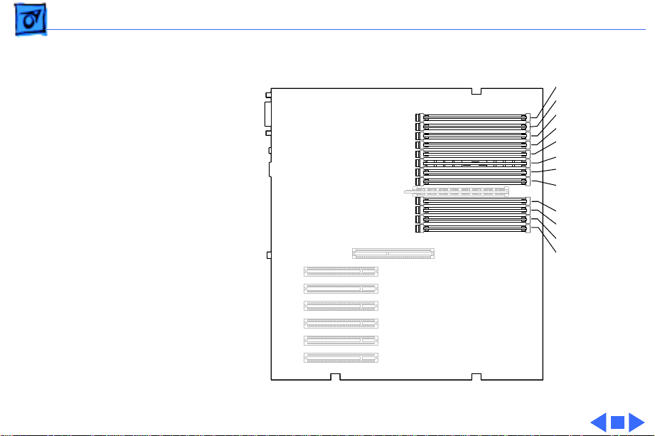
Basics Memory Configurations - 12
B6 slot
B5 slot
B4 slot
B3 slot
B2 slot
B1 slot
A6 slot
A5 slot
A4 slot
A3 slot
A2 slot
A1 slot
(front of
Computer)
Figure: Power Macintosh 9500 Memory Locations
Page 15

Basics Ethernet Support - 13
Ethernet Support
There are two Ethernet ports on the Power Macintosh 9500
Series logic board: an AAUI port and a 10BASE-T port. You
can use only one Ethernet port at one time, however. If you
have cables plugged into both Ethernet ports, the computer
uses the 10BASE-T port by default.
PC Compatibility Cards
Apple computer offers two PC Compatibility Card upgrade
kits that bring full DOS functionality to the Macintosh
computer. Two versions of the PC Compatibility card are
available: a 7" card and a 12" card. The cards plug into any
available PCI slot on the logic board. Refer to the Upgrades
chapter in this manual for installation instructions.
Page 16

Basics GeoPort - 14
GeoPort
Geoport is a hardware and software communications architecture that has been optimized for computer-telephony
integration. It has three main attributes:
• It lets any computer connect to any telephone (analog or
digital, public or private) anywhere in the world.
• Once connected, it supports an arbitrary number of
independent data streams up to a total bandwidth of 2 MB/
second.
• Unlike traditional asynchronous data communications
(such as AppleTalk), GeoPort also supports isochronous
data streams (such as real-time voice and video) and
provides the real-time Application Program Interfaces
(APIs) necessary to hide the implementation details
from both the recipient and the sender.
Page 17

Basics GeoPort - 15
By attaching an Apple GeoPort Telecom Adapter to the Power
Macintosh 9500, you can enjoy all the features of a 14.4
modem, including data, fax, send and receive, and voice
capabilities. The GeoPort Telecom Adapter serves as a line
interface to standard (analog) telephone lines. The adapter is
capable of sending or receiving data at up to 14.4 kbps and
faxes at up to 9600 bps using the GeoPort Telecom Adapter
software.
Page 18

Basics The Cuda Chip - 16
The Cuda Chip
The Cuda is a microcontroller chip. Its function is to
• Turn system power on and off
• Manage system resets from various commands
• Maintain parameter RAM (PRAM)
• Manage the Apple Desktop Bus (ADB)
• Manage the real-time clock
Many system problems can be resolved by resetting the Cuda
chip (see Symptom Charts for examples). Press the red
Cuda reset button on the logic board to reset the Cuda chip.
(See "Logic Board Diagram" later in this chapter to locate
the Cuda reset button.) If you continue to experience system
problems, refer to “Resetting the Logic Board” in this
Basics chapter.
Page 19

Basics Resetting the Logic Board - 17
Resetting the Logic Board
Resetting the logic board can resolve many system problems
(refer to "Symptom Charts" for examples). Whenever you
have a unit that fails to power up, you should follow this
procedure before replacing any modules.
1 Unplug the computer.
2 Remove the logic board. (Refer to the Take Apart chapter
for instructions on how to remove the logic board.)
3 Using a small flat-blade screwdriver, pry open the latch
at the end of the battery holder and lift off the battery
holder cover.
4 Remove the battery from its holder.
Page 20

Basics Resetting the Logic Board - 18
5 Verify the power supply cable is disconnected from the
logic board and then press the Power On button. (See
"Logic Board Diagram" later in this chapter to locate the
Power On button.)
6 Wait at least 10 minutes before replacing the battery.
Make sure the battery is installed in the correct +/direction.
7 Reassemble the computer and test the unit.
Note:
This procedure resets the computer’s PRAM. Be sure
to check the computer’s time/date and other system
parameter settings afterwards.
Note:
If this procedure resolves the problem, claim an
adjustment on an SRO. If not, replace the defective
component and DO NOT claim the adjustment procedure.
Page 21

Basics Fast SCSI - 19
Fast SCSI
The Power Macintosh 9500 Series computers offer Fast
SCSI support on the internal SCSI connector, which provides
for significantly enhanced data throughput. The internal
SCSI bus on these computers supports transfer rates up to
10 MB/sec.
Page 22

Basics Rear View Diagram - 20
Rear View Diagram
The Power Macintosh 9500 Series computers offer the
following external ports: SCSI, AAUI Ethernet, 10BASE-T
Ethernet, serial printer (GeoPort compatible), serial
modem (GeoPort compatible), ADB, sound input, and sound
output.
Some configurations of the Power Macintosh 9500 also
includes a DB-15 video port on the Apple Accelerated
Graphics card, which installs in one of the PCI slots on the
logic board.
The drawing on the next page illustrates the rear panel on
the Power Macintosh 9500 Series computers.
Page 23
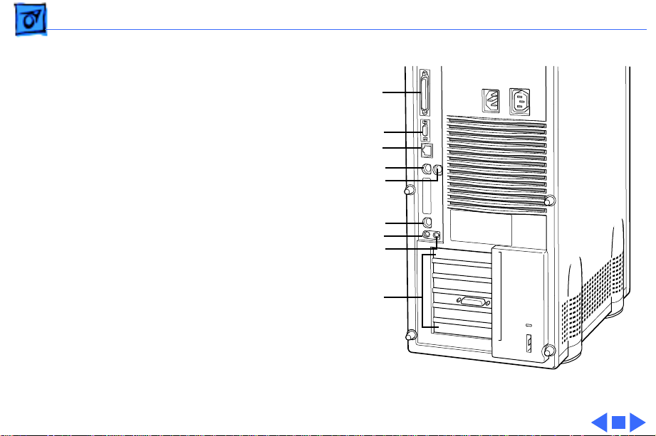
Basics Rear View Diagram - 21
SCSI
AAUI Ethernet
10BASE-T Ethernet
Printer
Modem
ADB
Sound In
Sound Out
PCI Slots
Figure: Power Macintosh 9500 Rear Panel
Page 24

Basics Logic Board Diagram - 22
Logic Board Diagram
The graphic on the following page illustrates the connectors
on the Power Macintosh 9500 Series logic board.
Note:
The board ships with 4 MB of ROM, which may either
be soldered or installed as a ROM SIMM.
Page 25
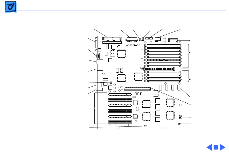
Basics Logic Board Diagram - 23
Internal SCSI
External
SCSI
AAUI
Ethernet
10BASE-T
Ethernet
Printer/
Modem
Cuda Reset
ADB
Sound
In/Out
Slots
Fan
PCI
Power
Supply
Speaker
CD-ROM
Audio
Floppy
Drive
Power Supply
Power Macintosh 9500 Logic Board
Battery
DRAM
DIMM
Slots
ROM
SIMM
DRAM
DIMM
Slots
ROM (4 MB)
Processor
Card Slot
Power LED
Power On/Off
Page 26
K
Service Source
Specifications
Power Macintosh 9500 Series
Page 27

Specifications Processor - 1
Processor
9500/120
9500/132
9500/150
PowerPC 604 RISC microprocessor running at 120 MHz
Built-in FPU
Requires system software version 7.5.2 or later with System
Enabler version 701
PowerPC 604 RISC microprocessor running at 132 MHz
Built-in FPU
Requires system software version 7.5.2 or later with System
Enabler version 701
PowerPC 604 RISC microprocessor running at 150 MHz
Built-in FPU
Requires system software version 7.5.3 or later with appropriate
System Enabler
Page 28

Specifications Processor - 2
9500/180MP
9500/200
Two PowerPC 604e RISC microprocessors each running at
180 MHz
Built-in FPU
Requires system software 7.5.3 Revision 2 or later
PowerPC 604e RISC microprocessor running at 200 MHz
Built-in FPU
Requires system software 7.5.3 Revision 2 or later
Page 29

Specifications Memory - 3
Memory
DRAM
ROM
Cache
Clock/Calendar
16 or 32 MB standard; expandable to 1536 MB
Uses 168-pin, 64-bit, 70 ns or faster DRAM DIMMs
4 MB ROM (may be installed in ROM SIMM slot, or soldered on the
logic board)
512K Level 2 cache soldered on the logic board
CMOS custom circuitry with long-life battery
Page 30

Specifications I/O Interfaces - 4
I/O Interfaces
SCSI
Serial
ADB
Ethernet
Dual-channel asynchronous SCSI interface; external channel
supports up to seven SCSI devices; internal channel supports a
hard disk array
Two RS-232/RS-422 serial ports compatible with LocalTalk and
GeoPort cables; mini DIN-8 connectors
One Apple Desktop Bus port for a keyboard, mouse, etc.
One AAUI and one 10BASE-T Ethernet port (if cables are plugged
into both ports, system defaults to 10BASE-T)
Page 31

Specifications I/O Interfaces - 5
Expansion
Sound
Video
9500/120, 9500/150, 9500/180MP, and 9500/200:
9500/132:
Six PCI expansion slots, compatible with all PCI 2.0
specification-compliant cards (not NuBus compatible)
16-bit stereo sound input and output ports
DB-15 video port for display on Apple Accelerated Graphics card
No built-in video support; requires separate video card
Page 32

Specifications I/O Devices - 6
I/O Devices
Keyboard
Mouse
Microphone
Standard, extended, or adjustable keyboard; keyboard draws
25-80 mA, depending on model type
ADB Mouse II; mouse draws up to 10 mA
Apple PlainTalk microphone standard
Page 33

Specifications Video Support - 7
Video Support
9500/120, 9500/150, 9500/180MP, and 9500/200
9500/132
Ships with Apple Accelerated Graphics card, which includes 2 MB
of VRAM (expandable to 4 MB via third-party memory module
expansion card); supports all Apple and most third-party
displays, including monochrome, color, VGA, and SVGA;
supports up to 16.7 million colors on Apple color displays up
to 17" and with 2 MB VRAM upgrade supports 16.7 million
colors on Apple displays up to 21"
No built-in video support; requires third-party video card for
display support
Page 34

Specifications Disk Storage - 8
Disk Storage
Hard Drive
9500/120:
9500/132, 9500/150, 9500/180MP, and 9500/200:
Floppy Drive
CD-ROM Drive
One 1 GB internal hard drive
One 2 GB internal hard drive
One Apple SuperDrive 1.4 MB floppy drive
One internal AppleCD 600i 4x-speed or 1200i 8x-speed
CD-ROM drive
Page 35

Specifications Electrical - 9
Electrical
Line V oltage
Frequency
Maximum Power
DC Power
AC Power
100—240 VAC, RMS single phase, automatically configured
50—60 Hz, single phase
225 W, not including monitor
340 W maximum continuous; 520 W peak input
Page 36

Specifications Physical - 10
Physical
Dimensions
Height
Width
Depth
Weight
16.9 in. (430 mm)
7.75 in. (196 mm)
15.75 in. (400 mm)
28 lb. (12.7 kg); weight varies depending on devices installed
Page 37

Specifications Environmental - 11
Environmental
Operating Temperature
Storage Temperature
50 to 104° F (10 to 40° C)
—40 to 116° F (—40 to 47° C)
Relative Humidity
Maximum Altitude
5% to 95% noncondensing
10,000 ft. (3,048 m)
Page 38

K
Service Source
Troubleshooting
Power Macintosh 9500 Series
Page 39

Troubleshooting General - 1
General
The Symptom Charts included in this chapter will help you
diagnose specific symptoms related to your product. Because cures
are listed on the charts in the order of most likely solution, try
the first cure first. Verify whether or not the product continues to
exhibit the symptom. If the symptom persists, try the next cure.
(Note: If you have replaced a module, reinstall the original module
before you proceed to the next cure.)
If you are not sure what the problem is, or if the Symptom Charts
do not resolve the problem, refer to the Flowchart for the product
family.
For additional assistance, contact Apple Technical Support.
Page 40

Troubleshooting Cleaning Procedure for Card Connectors - 2
Cleaning Procedure for Card Connectors
It is possible for residue to build up on the gold edge connector
pins on some PCI cards, which could cause a variety of symptoms.
If you are having problems with a PCI card, inspect the connector
pins with a magnifying glass. If you find residue, use a pencil
eraser to gently clean the pins.
Page 41

Troubleshooting Symptom Charts/Power Supply - 3
System doesn’t power
up
Symptom Charts
Power Supply
1 Reseat processor card, video card, and ROM SIMM (if
present).
2 Reset Cuda chip. (Refer to The Cuda Chip in Basics for
instructions.)
3 Reset logic board. (Refer to Resetting the Logic Board in
Basics for instructions.)
4 Replace power supply.
5 Replace processor card.
6 Replace logic board. Note: When you replace the logic board,
be sure the LED cable is not interfering with the power
actuator.
Page 42

Troubleshooting Symptom Charts/Error Chords - 4
Error Chords
One-part error
chord sounds during
startup sequence
1 Disconnect SCSI data cable from hard drive and reboot
system. If startup sequence is normal, initialize hard drive
using Drive Setup and then run Drive Setup Updater utility
program. Test unit again with SCSI data cable connected. If
error chord still sounds, replace hard drive.
2 Disconnect floppy drive cable from floppy drive and reboot
system. If startup sequence is normal, replace floppy drive.
3 Reseat processor card.
4 Replace processor card.
5 Replace logic board. Retain customer's DIMMs. Note: When
you replace the logic board, be sure the LED cable is not
interfering with the power actuator.
Page 43

Troubleshooting Symptom Charts/Error Chords - 5
Eight-part error
chord (death chimes)
sounds during
startup sequence
1 Make sure DRAM is installed first in banks A6 and B6,
followed by banks A5 and B5, etc. Do not install DRAM in
banks A1 and B1 until all other banks are full.
2 Replace DRAM DIMMs one at a time to test DRAM. Replace
any faulty DIMMs.
3 Replace logic board. Note: When you replace the logic board,
be sure the LED cable is not interfering with the power
actuator.
Page 44

Troubleshooting Symptom Charts/System - 6
System
Does not power on,
screen is black, fan is
not running and LED
is not lit
1 Check power cables.
2 Plug monitor directly into wall socket, and verify that
monitor has power.
3 Reseat ROM SIMM (if present) and processor card. The logic
board must have a processor card installed to operate.
4 Reset Cuda chip. (Refer to The Cuda Chip in Basics for
instructions.)
5 Reset logic board. (Refer to Resetting the Logic Board in
Basics for instructions.)
6 Replace power cord.
7 Replace power supply.
8 Replace processor card.
9 Replace logic board. Retain customer's DIMMs. Note: When
you replace the logic board, be sure the LED cable is not
interfering with the power actuator.
Page 45

Troubleshooting Symptom Charts/System - 7
Clicking, chirping,
or thumping
1 Remove all PCI cards and test the unit. If problem does not
occur with cards removed, begin replacing them one at a
time to determine which card is causing the problem.
Replace problem card with known-good card.
2 Remove hard drive. If problem no longer occurs, replace
hard drive with a known-good drive.
3 Replace power supply.
4 Replace processor card.
5 Replace logic board. Retain customer's DIMMs. Note: When
you replace the logic board, be sure the LED cable is not
interfering with the power actuator.
6 Replace floppy drive cable.
7 Replace floppy drive.
Page 46

Troubleshooting Symptom Charts/System - 8
System shuts down
intermittently
1 Make sure air vents are clear. Thermal protection
circuitry may shut down system. After 30 to 40 minutes,
system should be OK.
2 Make sure power cord is firmly plugged in.
3 Verify fan is plugged in and working. Replace if necessary.
4 Replace power cord.
5 Check battery.
6 Reset Cuda chip. (Refer to The Cuda Chip in Basics for
instructions.)
7 Reset logic board. (Refer to Resetting the Logic Board in
Basics for instructions.)
8 Replace power supply.
9 Replace processor card.
10 Replace logic board. Retain customer's DIMMs. Note: When
you replace the logic board, be sure the LED cable is not
interfering with the power actuator.
Page 47

Troubleshooting Symptom Charts/System - 9
System
intermittently
crashes or hangs
1 Verify system software is version 7.5.2 or later (Power
Macintosh 9500/120 and 9500/132) or 7.5.3 or later
(Power Macintosh 9500/150).
2 Verify DIMMs are noncomposite.
3 Verify software is known-good. Do a clean install of the
system software.
4 Verify software is Power Macintosh 9500 compatible
(contact developer). Also, try booting with extensions off to
determine if there are system init problems.
5 Clear parameter RAM. Hold down <Command> <Option> <P>
<R> during startup but before "Welcome to Macintosh"
appears.
6 Remove all DRAM DIMMs and try replacing them one at a
time to test. Replace any bad DIMMs.
7 Replace processor card.
8 Replace logic board. Retain DIMMs. Note: When you replace
the logic board, be sure the LED cable is not interfering with
the power actuator.
Page 48

Troubleshooting Symptom Charts/System - 10
During startup,
following message is
displayed, "This
startup disk will not
work on this
Macintosh model...."
1 Verify that startup disk is good.
2 Verify system software is version 7.5.2 or later (Power
Macintosh 9500/120 and 9500/132) or 7.5.3 or later
(Power Macintosh 9500/150).
3 Do a clean install of the system software.
Page 49

Troubleshooting Symptom Charts/Video - 11
Video
Screen is black, boot
tone is present, drive
operates, fan is
running, and LED is
lit
1 Adjust brightness on monitor.
2 Clear parameter RAM. Hold down <Command> <Option> <P>
<R> during startup but before "Welcome to Macintosh".
3 Verify video card is installed and reseat card.
4 Reset Cuda chip. (Refer to The Cuda Chip in Basics.)
5 Reset logic board. (See Resetting the Logic Board in Basics.)
6 Replace video cable.
7 Remove all DRAM DIMMs and try replacing them one at a
time to test. Replace any bad DIMMs.
8 Replace video card.
9 Test with known-good monitor. Replace monitor if
necessary. Refer to appropriate monitor manual to
troubleshoot defective monitor.
10 Replace processor card.
11 Replace logic board. Retain customer's DIMMs.
Page 50

Troubleshooting Symptom Charts/Video - 12
Screen is black, no
boot tone and drive
does not operate, but
fan is running and
LED is lit
1 Reset Cuda chip. (Refer to The Cuda Chip in Basics for
instructions.)
2 Reset logic board. (Refer to Resetting the Logic Board in
Basics for instructions.)
3 Remove all DRAM DIMMs and try replacing them one at a
time to test. Replace any bad DIMMs.
4 Replace processor card.
5 Replace logic board. Retain customer's DIMMs. Note: When
you replace the logic board, be sure the LED cable is not
interfering with the power actuator.
6 Replace power supply.
Page 51

Troubleshooting Symptom Charts/Video - 13
Boot tone is present
and screen lights up,
but nothing is
displayed on screen
1 Reset Cuda chip. (Refer to The Cuda Chip in Basics for
instructions.)
2 Reset logic board. (Refer to Resetting the Logic Board in
Basics for instructions.)
3 Replace video cable.
4 Replace video card.
5 Test with known-good monitor. Replace monitor if
necessary. Refer to appropriate monitor manual to
troubleshoot defective monitor.
6 Replace processor card.
7 Replace logic board. Retain customer's DIMMs. Note: When
you replace the logic board, be sure the LED cable is not
interfering with the power actuator.
Page 52

Troubleshooting Symptom Charts/ Floppy Drive - 14
Floppy Drive
Internal floppy drive
does not operate
During system
startup, disk ejects;
display shows icon
with blinking “X”
1 Replace floppy disk with known-good disk.
2 Replace floppy drive cable.
3 Replace floppy drive.
4 Replace processor card.
5 Replace logic board. Retain customer's DIMMs. Note: When
you replace the logic board, be sure the LED cable is not
interfering with the power actuator.
1 Replace disk with known-good system disk.
2 Replace floppy drive cable.
3 Replace floppy drive.
4 Replace processor card.
5 Replace logic board. Retain customer's DIMMs. Note: When
you replace the logic board, be sure the LED cable is not
interfering with the power actuator.
Page 53

Troubleshooting Symptom Charts/ Floppy Drive - 15
Does not eject disk 1 Switch off computer. Hold mouse button down while you
switch computer on.
2 Replace floppy drive cable.
3 Replace floppy drive.
4 Replace processor card.
5 Replace logic board. Retain customer's DIMMs. Note: When
you replace the logic board, be sure the LED cable is not
interfering with the power actuator.
Attempts to eject
disk, but doesn’t
1 Reseat floppy drive bezel and drive so bezel slot aligns
correctly with drive.
2 Replace floppy drive.
Page 54

Troubleshooting Symptom Charts/Floppy Drive - 16
Internal floppy drive
runs continuously
MS-DOS drive does
not recognize a disk
formatted on a 1.4 MB
drive
1 Replace disk with known-good floppy disk.
2 Replace floppy drive cable.
3 Replace floppy drive.
4 Replace processor card.
5 Replace logic board. Retain customer's DIMMs. Note: When
you replace the logic board, be sure the LED cable is not
interfering with the power actuator.
To read and write files with either MS-DOS or 1.4 MB drive,
format all disks with MS-DOS drive first.
Page 55

Troubleshooting Symptom Charts/Hard Drive - 17
Hard Drive
Single internal hard
drive does not
operate; drive
doesn’t spin
No internal SCSI
drives operate
1 Replace hard drive power cable.
2 Replace hard drive. If problem resolved, reinstall SCSI
device driver and system software.
3 Replace power supply.
1 Verify there are no duplicate SCSI device addresses.
2 Disconnect external SCSI devices and check for proper
termination. Only last device in SCSI chain should be
terminated.
3 Replace SCSI data cable.
4 Replace power supply.
5 Replace processor card.
6 Replace logic board. Retain customer's DIMMs. Note: When
you replace the logic board, be sure the LED cable is not
interfering with the power actuator.
Page 56

Troubleshooting Symptom Charts/ Hard Drive - 18
Drive does not appear
on the desktop
Works with internal
or external SCSI
devices but not with
both
1 Verify there are no duplicate SCSI device addresses.
2 Update the SCSI device driver using Drive Setup and then run
Drive Setup Updater utility program. Run Disk First Aid to
verify the condition of the drive's directory structure.
3 Replace the SCSI hard drive cable.
4 If drive is not initialized, use Drive Setup to initialize it and
then run Drive Setup Updater utility program.
5 Replace with known-good hard drive.
6 If the hard drive still doesn't work, switch back to the
original hard drive and replace the logic board.
1 Verify there are no duplicate SCSI device addresses.
2 Replace terminator on external SCSI device.
3 Verify that SCSI device at end of internal SCSI data cable is
only device terminated.
4 Refer to appropriate manual to troubleshoot defective
external device.
Page 57

Troubleshooting Symptom Charts/Peripherals - 19
Peripherals
Cursor does not move 1 Check mouse connection.
2 Inspect inside of mouse for buildup of dirt or other
contaminants. Clean mouse if necessary.
3 If mouse was connected to keyboard, connect mouse to
computer ADB port instead. If mouse works, replace
keyboard.
4 Replace ADB cable.
5 If mouse does not work in any ADB port on computer, replace
mouse.
6 Replace processor card.
7 Replace logic board. Retain customer's DIMMs. Note: When
you replace the logic board, be sure the LED cable is not
interfering with the power actuator.
Page 58

Troubleshooting Symptom Charts/Peripherals - 20
Cursor moves, but
clicking mouse
button has no effect
Double-click doesn’t
open application,
disk, or server
1 Boot from floppy or bootable CD.
2 Replace mouse.
3 Replace logic board. Retain customer's DIMMs. Note: When
you replace the logic board, be sure the LED cable is not
interfering with the power actuator.
1 Remove duplicate system folders.
2 Clear parameter RAM. Hold down <Command> <Option> <P>
<R> during startup but before "Welcome to Macintosh"
appears.
3 If mouse was connected to keyboard, connect mouse to
computer ADB port instead. If mouse works, replace
keyboard.
4 If mouse does not work in any ADB port on computer, replace
mouse.
5 Replace logic board. Retain customer's DIMMs. Note: When
you replace the logic board, be sure the LED cable is not
interfering with the power actuator.
Page 59

Troubleshooting Symptom Charts/Peripherals - 21
No response to any
key on keyboard
Known-good serial
printer does not work
1 Check keyboard connection to ADB port.
2 Replace keyboard cable.
3 Replace keyboard.
4 Replace logic board. Retain customer's DIMMs. Note: When
you replace the logic board, be sure the LED cable is not
interfering with the power actuator.
1 Verify you have correct version of system software.
2 Verify that Chooser is set correctly.
3 Reinstall correct printer drivers.
4 Do clean install of system software.
5 Replace printer interface cable.
6 Replace logic board. Retain customer's DIMMs. Note: When
you replace the logic board, be sure the LED cable is not
interfering with the power actuator.
Page 60

Troubleshooting Symptom Charts/Peripherals - 22
Known-good network
printer does not print
1 Check network connections.
2 Verify you have correct version of system software.
3 Verify that Chooser is set correctly.
4 Does printer show up in Chooser? If so, do clean install of
system software and/or network and printer software.
5 Replace logic board. Retain customer's DIMMs. Note: When
you replace the logic board, be sure the LED cable is not
interfering with the power actuator.
Page 61

Troubleshooting Symptom Charts/CD-ROM Drive - 23
CD-ROM Drive
CD-ROM drive does
not work
Macintosh does not
display CD-ROM icon
once CD is inserted in
drive
Computer with 600i
CD-ROM drive makes
stuttering sounds
when playing CD+ or
CD-R formatted
discs or CD-ROM disc
won’t mount
1 Try using known-good compact disc.
2 Replace CD-ROM drive mechanism.
1 Verify that CD-ROM software is installed.
2 Replace CD-ROM drive mechanism.
3 Replace SCSI data cable.
Replace CD-ROM drive.
Page 62

Troubleshooting Symptom Charts/Miscellaneous - 24
Miscellaneous
No sound from
speaker
1 Verify that volume setting in Control Panel is 1 or above.
2 Clear parameter RAM. Hold down <Command> <Option> <P>
<R> during startup but before "Welcome to Macintosh"
appears.
3 Verify speaker is plugged into logic board.
4 Replace speaker.
5 Replace logic board. Retain customer’s DIMMs.
Page 63

Troubleshooting Symptom Charts/Miscellaneous - 25
Errors occur when
initializing or erasing
floppy disks and/or
1.4 MB disks show
only 1 MB available
after initialization
This problem only occurs on systems using a 180 MHz or faster
processor card. Upgrade to system software version 7.5.4 to
resolve this problem (the Apple recommended solution) or,
alternatively, install the Power Mac Format Patch, which can be
found on the original system disks that shipped with the computer.
To install the patch:
• While holding down the Option key, drag the Power Mac
Format Patch icon onto the System Folder’s icon.
• Click OK to automatically place the patch in the Extensions
folder.
• Restart the computer by choosing Restart from the Special
menu.
Page 64

K
Service Source
T ak e Apart
Power Macintosh 9500 Series
Page 65

Take Apart Top Housing - 1
Top Housing
Top Housing
No preliminary steps are
required before you begin
this procedure.
Note:
The top housing covers
the top, front, and left and
right sides of the computer.
IMPORTANT
the computer with the top
housing removed. Failure to
comply may result in
irreparable damage to
internal components.
: Never operate
Page 66

Take Apart Top Housing - 2
1 Loosen the six captive
cover screws on the rear
panel and slide the top
housing forward about
4
1
5
2
6
3
1/2 an inch.
Page 67

Take Apart Top Housing - 3
2 Lift straight up on the
top housing to remove it
Top Housing
from the computer.
Page 68

Take Apart CD-ROM Drive - 4
CD-ROM Drive
CD-Rom Drive
Before you begin, remove
the top housing.
Note:
The CD-ROM drive is
located in the top drive bay.
Page 69

Take Apart CD-ROM Drive - 5
1 Disconnect the SCSI data
CD-Rom Audio Cable
CD-Rom Drive
Power CableSCSI Data Cable
cable, audio cable, and
power cable from the
back of the CD-ROM
drive.
Page 70

Take Apart CD-ROM Drive - 6
2 Pull up on the retaining
clip at the back of the
CD-ROM drive and slide
the drive forward to
remove it from the
computer.
Note:
Be sure to remove the
CD-ROM drive from its
carrier before returning the
drive to Apple.
Page 71

Take Apart Floppy Drive - 7
Floppy Drive
Before you begin, remove
the following:
• Top Housing
• CD-ROM Drive
Floppy
Drive
Note:
The floppy drive is
located in the second drive
bay from the top.
Page 72

Take Apart Floppy Drive - 8
1 Disconnect the floppy
Plastic Guides
drive cable from the
logic board and remove
the cable from the
plastic guides.
Floppy Drive
Floppy Drive Cable
Page 73

Take Apart Floppy Drive - 9
2 Press down the retaining
clip at the back of the
floppy drive and slide
the floppy drive
forward about two
inches.
3 Disconnect the floppy
drive cable from the
back of the floppy drive
and remove the floppy
drive from the
computer.
Replacement Note:
to remove the floppy drive
from its carrier before
returning the drive to Apple.
Be sure
Page 74

Take Apart Hard Drive - 10
Hard Drive
Before you begin, remove
the top housing.
Note:
The hard drive is
located in the bottom drive
bay.
Hard
Drive
Page 75

Take Apart Hard Drive - 11
1 Disconnect the SCSI data
SCSI Data Cable
cable and hard drive
power cable from the
hard drive.
Hard DriveHard Drive Power Cable
Page 76

Take Apart Hard Drive - 12
2 Press down the retaining
clip at the back of the
hard drive and slide the
hard drive forward to
remove it from the computer.
Note:
For information on
removing the hard drive
from its carrier and
returning drives, cables,
and carriers to Apple, refer
to Additional Procedures in
the Hard Drives manual.
Page 77

Take Apart Power Supply - 13
Power Supply
Before you begin, remove
the top housing.
Note:
As you face the
Power
Supply
computer, the power supply
is located in the back of the
chassis, directly beneath the
speaker.
Page 78

Take Apart Power Supply - 14
1 Disconnect the two
cables that run from the
power supply to the logic
board.
Note:
The 10-pin power
supply cable (the cable on
the left in the graphic)
supplies 3.3 V power for the
processor card. The 22-pin
cable (the cable on the right
in the graphic) supplies 5 V
and +/- 12 V power for the
logic board.
Power Supply Cable
Power Supply Cable
Page 79

Take Apart Power Supply - 15
2 Turn the computer
sideways so you are
Power Supply
facing the power supply.
(The power supply
should be to your left and
the drive bays to your
right.)
3 Locate the chassis
support brace, which is
between the power
supply and the drive
bays.
Page 80

Take Apart Power Supply - 16
4 Push in on the latch
located on the right side
Chassis Support Brace
of the chassis support
brace and pull out the
brace to remove it.
Page 81

Take Apart Power Supply - 17
5 Push in on the plastic
Power Supply
latch that secures the
power supply to the
chassis. The latch is
located to the right of the
power supply.
Latch
Page 82

Take Apart Power Supply - 18
6 Slide the power supply
forward and pull it out of
the computer.
7 Remove the 22-pin
cable from the power
supply.
Replacement Note:
are two metal tabs on the
back of the power supply on
its bottom edge. You must
feed these tabs through two
openings in the chassis
before you slide the power
supply back into place.
There
Page 83

Take Apart Speaker - 19
Speaker
Speaker
Before you begin, remove
the top housing.
Note:
As you face the
computer, the speaker is on
top of the chassis at the back
end of the computer.
Page 84

Take Apart Speaker - 20
1 Disconnect the speaker
Speaker
cable from the logic
board.
Speaker Cable
Page 85

Take Apart Speaker - 21
2 Press the latch holding
the speaker housing to
the chassis and lift the
front of the speaker
housing.
Speaker
Page 86

Take Apart Speaker - 22
3 Pull the speaker
housing from the clips at
the rear of the chassis.
Page 87

Take Apart Rear Panel - 23
Rear Panel
Before you begin, remove
the following:
• Top Housing
• Speaker
Note:
Rear
Panel
To locate the rear
panel, turn the computer so
the back faces you. The rear
panel is the back part of the
housing.
Page 88

Take Apart Rear Panel - 24
1 Two plastic tabs at the
top of the rear panel
Plastic Tab Plastic Tab
secure the rear panel to
the chassis. Lift the two
tabs to release them.
Page 89

Take Apart Rear Panel - 25
2 Pull out on the rear
Plastic Tabs
panel and lift up
slightly to release the
two bottom tabs that
secure the rear panel to
the chassis.
Plastic Tabs
Page 90

Take Apart Processor Card - 26
Processor Card
Before you begin, remove
the following:
• Top Housing
• Fan
Note:
As you face the
computer, the processor
card is plugged into the logic
board on the left side,
directly beneath the power
supply.
Note:
For better access, lay
Processor
Card
the computer on its side
with the power supply
facing up.
Page 91

Take Apart Processor Card - 27
Plastic Guide Plastic Guide
Warning:
The heat sink may
be hot to the touch.
1 Grab the corners of the
processor card (and the
top of the heat sink if it
is cool to the touch) and
pull straight up on the
card to remove it.
Replacement Note:
Position
the bottom edges of the card
in the plastic guides and
press down on the card to
install it. Do not force the
card or you may damage it.
Make sure the card is seated
evenly.
Page 92

Take Apart PCI/Video Cards - 28
PCI/Video Cards
Before you begin, remove
the following:
• Top Housing
• Fan
Note:
As you face the
computer, PCI cards (such
as the Apple Accelerated
Graphics card) plug into the
logic board on the left side.
Note:
For better access, lay
the computer on its side
Video
Card
with the power supply
facing up.
Page 93

Take Apart PCI/Video Cards - 29
1 Push apart the plastic
Plastic Latches
latches that secure the
PCI card to the chassis
and pull up on the card to
remove it.
Video Card
Page 94

Take Apart PCI/Video Cards - 30
VRAM Upgrade Card
Important:
If you are
returning an Apple
Accelerated Graphics card,
you must first remove the
third-party VRAM upgrade
card if one is installed.
2 Grab the edges of the
VRAM upgrade card and
lift straight up on the
card to remove it.
Page 95

Take Apart PCI/Video Cards - 31
VRAM Upgrade Card
Arrows
Replacement Note:
To
replace the third-party
VRAM Upgrade card, line up
the arrows on the two cards,
as shown in the graphic on
the left, and gently press
down on the VRAM upgrade
card. Do NOT force the
upgrade card. If you
encounter resistance, first
make sure you have the card
lined up properly, and try
again.
Page 96

Take Apart Logic Board - 32
Logic Board
Before you begin, remove
the following:
• Top Housing
Logic
Board
• Fan
• Processor Card
• PCI/Video Cards (e.g.,
Apple Accelerated
Graphics Card)
Note:
As you face the rear of
the computer, the logic
board is on the left side and
is perpendicular to the
bottom chassis.
Page 97

Take Apart Logic Board - 33
1 Disconnect all cables
from the top of the logic
board.
Power
Supply
Cable
Floppy
Drive
Cable
CD-Rom
Audio
Cable
Speaker
Cable
Power
Supply
Cable
SCSI
Cable
Page 98

Take Apart Logic Board - 34
2 Locate the power
Tab
actuator at the bottom of
the logic board. Press in
on the two plastic tabs to
remove the actuator
from the logic board.
Tab
Page 99

Take Apart Logic Board - 35
3 Remove the screw
securing the logic board
to the chassis.
Page 100

Take Apart Logic Board - 36
4 Slide the logic board
forward until the slot
indicated lines up with
the latch on the chassis.
 Loading...