

Page 1
K
Service Source
Performa 6200/6300 Series
Performa 6200, 6205CD, 6214CD, 6216CD, 6218CD,
6220CD, 6230CD, 6290,
6300CD, 6320, 6320CD, 6360
Page 2
K
Service Source
Basics
Performa 6200/6300 Series
Page 3

Basics General Information - 1
General Information
Overview
The Macintosh Performa 6200 and 6300 Series computers
feature the PowerPC 603 processor and include slots for
• Video-in card
• LC-processor-direct slot (LC-PDS) card (not on
Performa 6360)
• Ethernet or modem card
• Peripheral component interconnect (PCI) card
(Performa 6360)
The 6200 Series computers ship with an IDE hard drive, an
internal 14.4 Global Village modem, and a 600i CD-ROM
drive (optional).
Page 4

Basics General Information - 2
User Controls
User controls include
• Soft power-on control from the keyboard
• Front panel sound-control pushbuttons
• Optional infrared remote control
Page 5

Basics General Information - 3
Internal Expansion Connections
The following expansion slots are included on the logic board:
• DRAM SIMM expansion slot (1 or 2 slots), DRAM DIMM
expansion sockets on the Performa 6360
• LC PDS slot (already populated in the LC 630 DOSCompatible, no PDS slot on 6360)
• PCI slot on the Performa 6360
• Communications slot for modems and Ethernet
• Video-in slot for real-time video display, capture, and
overlay
In addition to expansion slots on the logic board, an
expansion ribbon connector for an optional TV tuner card
also is included. The TV-tuner connector provides NTSC and
PAL input from an external TV antenna or cable.
Page 6

Basics Performa 6320CD and 6300CD - 4
Performa 6320CD and 6300CD
The Performa 6320CD supersedes the Performa 6300CD.
The Performa 6320CD has a 603e processor at 120 MHz,
while the Performa 6300CD has a 603e processor at 100
MHz. All other hardware features are the same as the
6300CD.
Page 7

Basics Performa 6360 - 5
Performa 6360
The Performa 6360 differs from previous models in this
computer family with these features:
• PowerPC 603e processor with a 160 MHz processor
clock
• 16 MB of DRAM expandable to 136 MB in two DIMM
sockets
• PCI expansion slot
• GeoPort-compatible serial ports
Page 8

Basics Open Transport - 6
Open Transport
Open Transport 1.1 does not work on 6200 or 6300 Series
computers. These computers require Open Transport 1.1.1.
When version 1.1.1 is installed on these computers, a dialog
box may appear indicating that a hardware issue was
detected. This message means that Open Transport can’t be
installed until the cache/ROM DIMM is replaced.
The required repairs are covered under the Apple Repair
Extension Program. The models included in this program are
Macintosh Performa 6200, 6205, 6214, 6216, 6218,
6220, 6230, 6290, and 6300. Look for repair program
instructions in the REA Procedures chapter.
Page 9

Basics Processor-Direct Slot (PDS) - 7
Processor-Direct Slot (PDS)
The LC-processor direct slot (LC-PDS) is compatible with
the PDS in the Macintosh LC family of computers, but it is
not a true PDS. While this expansion slot supports many
PDS cards designed to operate with the MC68030 bus, some
of those cards do not work. PDS cards designed to interact
with the main processor—to provide, for example, a RAM
cache or an FPU—will not work in the I/O expansion slot.
Page 10

Basics Peripheral Component Interconnect (PCI) - 8
Peripheral Component Interconnect (PCI)
The Performa 6360 offers a peripheral component
interconnect (PCI) expansion bus. Because the PCI bus is an
industry standard, most existing PCI 2.0-compliant cards
(with the addition of a Mac OS-specific software driver)
will work in these computers.
PCI offers significantly higher performance than the NuBus
architecture used in previous Macintosh models. Running at
33 MHz, the PCI bus is up to three times faster than NuBus,
offering overall enhanced system performance
(particularly in the areas of video and networking).
Page 11

Basics Video-In Card - 9
Video-In Card
The video-in card is an optional card included with the Apple
TV/Video System. It allows users to digitize video from the
TV tuner, and external composite or S-video input. It
accepts NTSC, PAL, or SECAM format video and also provides
stereo audio input.
Page 12

Basics TV Tuner Module - 10
TV Tuner Module
The TV tuner, an optional module included with the Apple
TV/Video System, turns the computer into a television
receiver. The TV tuner requires the video-in card, which is
also included with the Apple TV/Video System.
The TV tuner receives incoming television signals from
cable or antenna television input and then sends the
information to the video-in card, which converts the data
for display on the screen. In the United States, only NTSC is
supported, but PAL and SECAM are available internationally.
Page 13

Basics GeoPort (Performa 6360) - 11
GeoPort (Performa 6360)
GeoPort is a hardware and software communications
architecture that has been optimized for computertelephony integration. It has the following attributes:
• It allows users to connect any GeoPort-compatible
computer to any telephone (analog or digital, public, or
private) anywhere in the world.
• Once connected, it supports an arbitrary number of
independent data streams up to a total bandwidth of 2
MB/second.
• Unlike traditional asynchronous data communications
(such as AppleTalk), GeoPort also supports isochronous
data streams (such as real-time voice and video) and
provides the real-time Application Program Interfaces
(APIs) necessary to hide the implementation details
from both the recipient and the sender.
Page 14

Basics Dual In-Line Memory Modules (DIMMs) - 12
Dual In-Line Memory Modules (DIMMs)
The Performa 6360 uses DRAM Dual In-Line Memory
Modules (DIMMs) instead of DRAM Single In-Line Memory
Modules (SIMMs). Whereas SIMMs have 72 pins, DIMMs
have 168 pins. The extra pins provide a 64-bit data path,
compared to a 32-bit data path for SIMMs. In addition,
DIMMs do not have to be installed in pairs like the SIMMs on
earlier Macintosh models.
Important:
are
not
compatible with the Performa 6360.
The SIMMs used in previous Macintosh models
Page 15

Basics Dual In-Line Memory Modules (DIMMs) - 13
DRAM DIMMs can be installed individually. However, to take
advantage of the computer’s interleaving capability (which
provides maximum performance), you must install the
DIMMs in matching pairs. Memory interleaving allows the
computer to read or write to its memory while other
memory reads or writes are occurring, providing faster
performance.
Note:
DIMMs purchased from different manufacturers can
be paired as long as they are the same size and speed.
Page 16

Basics Intelligent Device Electronics (IDE) Drive - 14
Intelligent Device Electronics (IDE) Drive
The internal hard drive uses Intelligent Device Electronics
(IDE) technology, commonly used in DOS-compatible
systems. The internal IDE hard drive functions the same as a
typical SCSI hard drive. You must replace IDE drives likefor-like.
The IDE drive does not affect SCSI ID selections or SCSItermination schemes. Seven external SCSI devices may be
daisy-chained through the external SCSI port.
Page 17

Basics Plastic Panel Design - 15
Plastic Panel Design
The computer is designed for easy service. Plastic panels
cover the metal bottom case, the metal top cover shield, and
the left, right, and rear sides of the metal case.
To service the logic board, remove the rear plastic panel and
slide out the logic board. To access the drives, remove the
front plastic panel.
Page 18
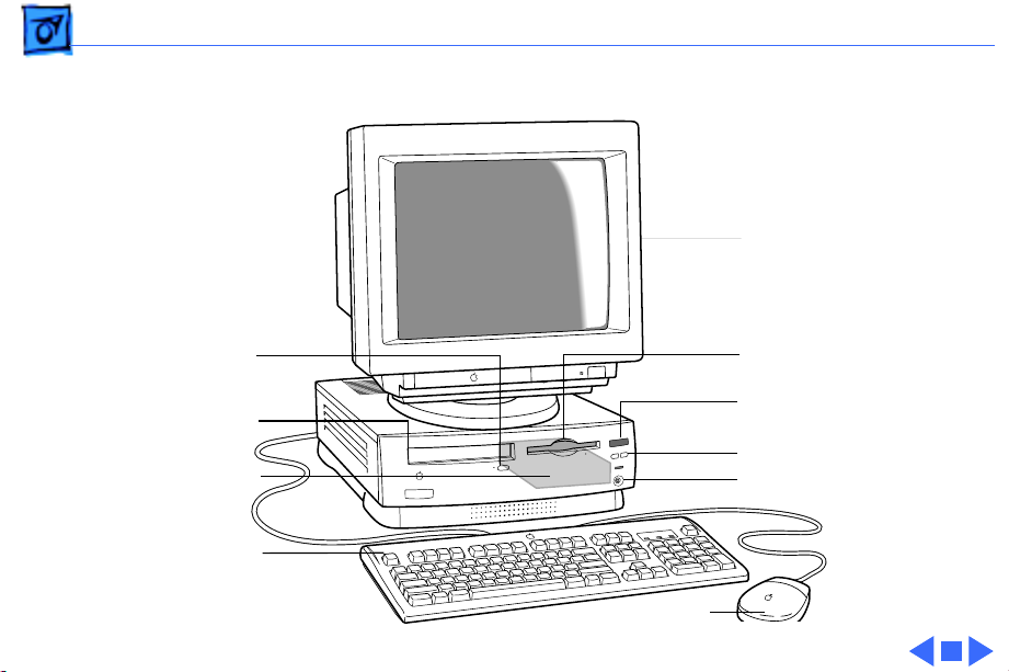
Basics Front View - 16
Front View
Monitor
CD-ROM Drive
Open/Close Button
CD-ROM Drive
(Optional)
Internal Hard
Drive
Keyboard
Floppy Drive
Remote Control Sensor
Volume Buttons
Headphone Jack
Mouse
Page 19
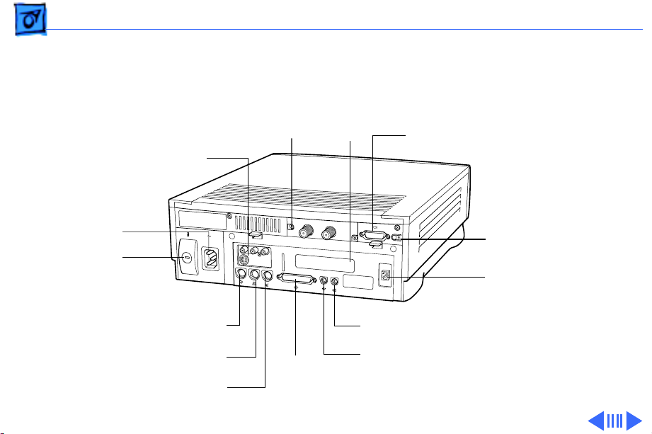
Basics Performa 6360 Rear View - 17
Performa 6360 Rear View
TV/FM
Tuner
Card
(Optional)
Video-In Card (Optional)
PCI
Card
Access
Cover
Monitor
Port
Power Socket
Security
Lock Port
Apple Desktop Bus
External Modem Port
(ADB) Port
Printer Port
Standby Power
Button
Internal Modem Card
(Optional)
Sound Output Port
Sound Input Port
SCSI
Port
Page 20
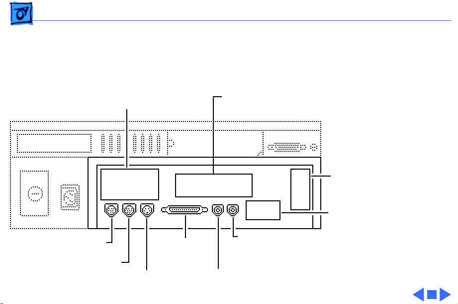
Basics I/O Door Diagram - 18
I/O Door Diagram
Access Cover for
Optional Video Input Card
ADB Port
Printer Port
Modem Port
SCSI Port
Sound Input Port
Access Cover for
Optional External Video Out
Access Cover
for Optional
Communication
Card
Access Cover
for Optional PDS
Sound Output Port
Expansion Card
Page 21
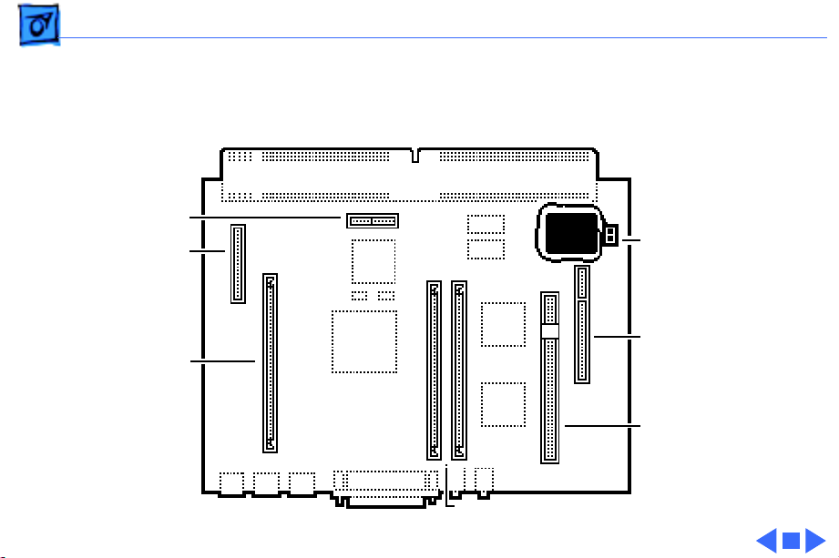
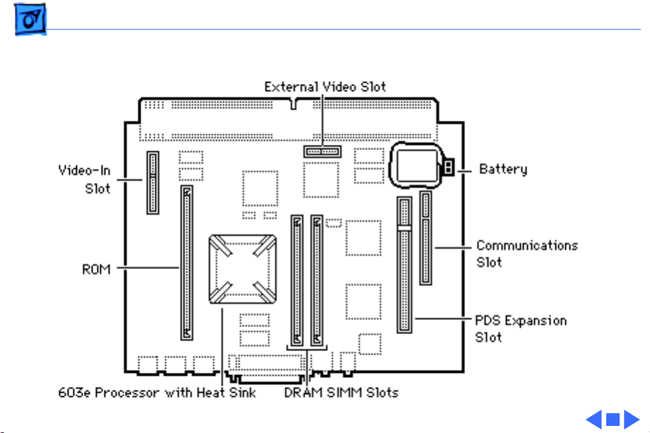
Basics Logic Board Diagrams - 19
Logic Board Diagrams
Performa 6200 Series
External Video Slot
Video-In Slot
ROM
DRAM SIMM Slots
Battery
Communications Slot
PDS Expansion Slot
Page 22
Basics Logic Board Diagrams - 20
Performa 6300 (except 6360)
Page 23
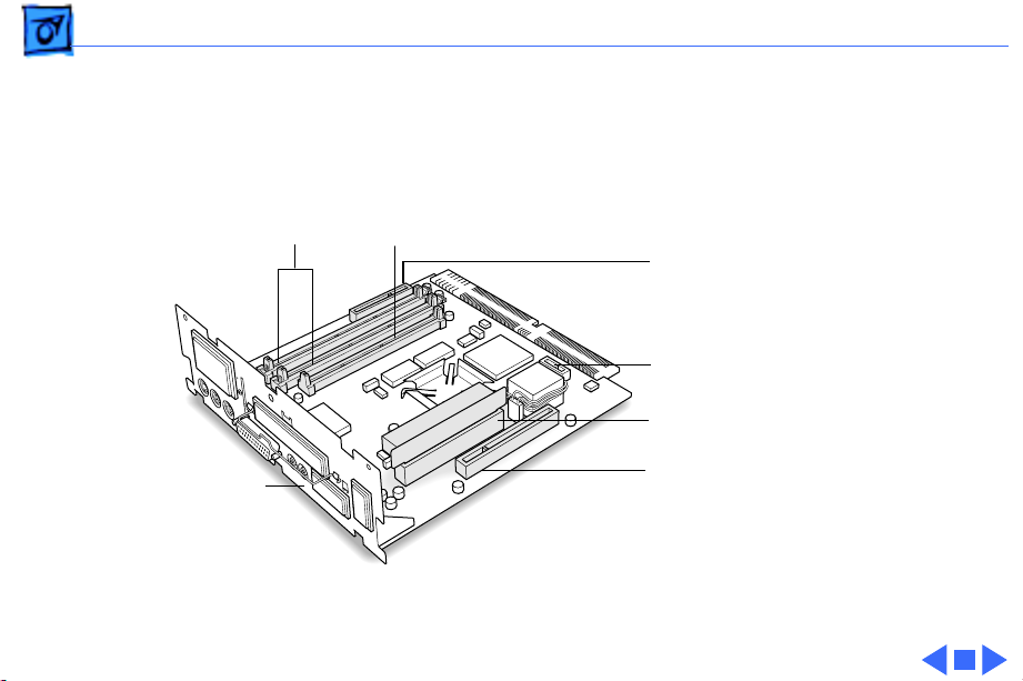
Basics Logic Board Diagrams - 21
Performa 6360
DRAM DIMM
Slots (2)
Logic
Board
Fence
Cache
Slot
Video-In Slot
Monitor-Out Slot
PCI Slot and
PCI Card Adapter
Communications Slot
Page 24
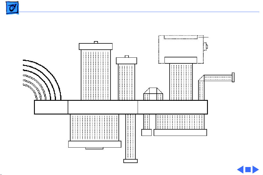
Basics Shield/Wiring Harness - 22
Shield/Wiring Harness
26-Pin IR
Connector
Power
Connector
20-Pin Floppy
Drive Connector
40-Pin IDE Connector
Monitor Out
Daughterboard
CD Audio
4-Pin
CD
Audio
10-Pin TV Tuner Connector
30-Pin
CD Connector
DB-15 Video
Connector
6-Pin Header
to P/S
Page 25

K
Service Source
Specifications
Performa 6200/6300 Series
Page 26

Specifications Processor - 1
Processor
Performa 6200
Performa 6290 and 6300
Performa 6320CD
Performa 6360
Addressing
PowerPC 603 processor
75 MHz
PowerPC 603e processor
100 MHz
PowerPC 603e processor
120 MHz
PowerPC 603e processor
160 MHz
64-bit PowerPC bus
Page 27

Specifications Memory - 2
Memory
DRAM
Performa 6200 Series
Performa 6300 Series (except 6360)
Performa 6360
8 MB DRAM, minimum, in one SIMM slot
Expandable to 64 MB in two SIMM slots (72-pin, 80 ns or faster
SIMMs)
16 MB DRAM
Expandable to 64 MB in two SIMM slots (72-pin, 80 ns or faster
SIMMs)
16 MB DRAM
Expandable to 136 MB in two sockets (168-pin, 70 ns or faster
DIMMs)
Page 28

Specifications Memory - 3
DRAM Frame Buffer
ROM
Cache Memory
1 MB DRAM on board, for video support
4 MB
256K Level 2
Page 29

Specifications Disk Storage - 4
Disk Storage
Floppy Drive
CD-ROM Drive
Performa 6360/160
Hard Drive
Performa 6360/160
1.4 MB Apple SuperDrive manual insert drive
Optional Apple 600i Plus CD-ROM drive
8X CD-ROM
I GB IDE
1.2 GB IDE
Page 30

Specifications I/O Interfaces - 5
I/O Interfaces
Serial
6200 and 6300 Series (except 6360)
Performa 6360
SCSI
Apple Desktop Bus
Two RS-232/422 serial ports; mini DIN-8 connectors
Two RS-232/RS-422 serial GeoPort-compatible ports
One external SCSI port; DB-25 connector
Supports up to seven SCSI devices
One Apple Desktop Bus (ADB) port; mini DIN-4 connector
Page 31

Specifications I/O Interfaces - 6
Sound Input
6200 and 6300 Series
Performa 6360
Sound-input port for microphone or line input
Note:
The port accepts stereophonic input, but sound is
combined into monophonic sound for play-through or
recording.
One sound input port for stereo sound input
Page 32

Specifications I/O Interfaces - 7
Sound Output
6200 and 6300 Series (except 6360)
Performa 6360
External Video Connector
Two stereophonic sound-output ports, level nominally 0.5 V RMS
into 39 ohms (one front headphone jack, one rear stereo mini
phone jack)
Internal stereo speakers
One front headphone jack
One rear sound output port for line-level devices
One built-in speaker
One DB-15 mirror video-out connector using optional video
connector kit; this feature provides “mirroring” (or display
of the system monitor screen on a presentation screen)
Note:
The external video display is presentation only. It cannot
be manipulated directly by mouse or other input signals.
Page 33

Specifications I/O Interfaces - 8
Video-in Slot
TV Tuner
Processor-Dir ect Slot (PDS) not on 6360
Peripheral
Component
Interconnect (PCI)
on Performa 6360
Communications Slot
One 60-pin video-in slot for optional expansion card providing
real-time video display, capture, and overlay
One 10-pin port for optional TV tuner card
One 96/114-pin internal expansion slot for LC-compatible
processor-direct card
One internal expansion slot supporting 6.88-inch PCI expansion
cards
One 112-pin internal expansion slot for modem or Ethernet card
Performa 6205CD is bundled with the 28.8 baud modem
Page 34

Specifications I/O Interfaces - 9
Controls
Soft power-on control from keyboard
Front panel pushbutton control for sound volume
Infrared remote control
Page 35

Specifications I/O Devices - 10
I/O Devices
Keyboard
Mouse
Microphone
Speaker
AppleDesign, Apple Extended Keyboard II (other ADB keyboards
supported)
ADB Mouse II
Mechanical tracking, optical shaft, or contact encoding
Integrated microphone for monophonic sound input
Integrated stereo speakers capable of delivering 16-bit stereo
sound
Page 36

Specifications Sound and Video - 11
Sound and Video
Sound
6200 and 6300 Series (except 6360)
Records at 11 kHz or 22 kHz sample rate
Plays back at 22 kHz sample rate
Two speakers with enhanced stereo sound
Allows playback and recording of ordinary audio compact discs
16-bit monophonic sound input
16-bit stereophonic sound output (16-bit CD stereophonic
playback), level nominally 0.5 V RMS into 39 ohms
Sound-input port for microphone or line input; accepts
stereophonic input, but sound is combined into monophonic
sound for play-through or recording
Two stereophonic sound output ports, level nominally 0.5 V RMS
into 39 ohms
Internal speaker muted when a plug is inserted into an output jack
Page 37

Specifications Sound and Video - 12
Sound
Performa 6360
Video Screen (not
on Performa 6360/
160)
Sample rates of 11.025, 22.05, and 44.1 kHz
16-bit stereophonic input
16-bit stereophonic output featuring SRS 3D Surround Sound
technology
Sound-input connector line level 2 Vpp maximum, into 10
kilohms impedance
Sound-output connector line level 2 Vpp maximum, into 32 ohms
impedance
15-inch 0.28 mm dot-pitch cathode-ray tube (CRT)
Page 38

Specifications Sound and Video - 13
Video Resolution
6200 and 6300 Series (except 6360)
Performa 6360
640 x 480 resolution with 16-bit color at 67 Hz or 60 Hz (VGA)
800 x 600 resolution with 8-bit color at 60 Hz or 72 Hz (VGA)
832 x 624 resolution with 8-bit color at 75 Hz (does not support
video input)
640 x 480 resolution with 16-bit color at 60 Hz or 67 Hz
800 x 600 resolution with 16-bit color at 60 Hz (supports video
input at 8-bit or less color depth)
800 x 600 resolution with 8-bit color at 72 Hz (does not support
video input)
832 x 624 resolution with 8-bit color at 75 Hz
1024 x 768 resolution with 8-bit color at 60 Hz or 70 Hz (does
not support video input)
Page 39

Specifications Sound and Video - 14
Video Mirroring
With the external video connector kit, the Macintosh Performa
6200CD series supports video mirroring on these monitors:
• 640 x 480 resolution: Macintosh 12" Color Display, Apple
Color Plus 14" Display, Apple Performa Plus Display, Apple
Multiple Scan 15 Display, Apple Multiple Scan 17 Display, and
Apple Multiple Scan 20 Display
• 800 x 600 resolution: Apple Multiple Scan 15 Display, Apple
Multiple Scan 17 Display, Apple Multiple Scan 20 Display, and
SVGA monitors
Page 40

Specifications Electrical - 15
Electrical
Line V oltage
6200 and 6300 Series (except 6360)
Performa 6360
Frequency
6200 and 6300 Series (except 6360)
Performa 6360
100–240 VAC
90–270 VAC
47–63 Hz
43–67 Hz
Page 41

Specifications Electrical - 16
Power
6200 and 6300 Series (except 6360)
Performa 6360
125 watts
Surge Voltage: 300 V RMS for 100 ms
Peak Inrush Current: 40 A pk
Current: 2.5 A maximum for all line and load conditions
Power: 220 W maximum for all line and load conditions
150 watts
Page 42

Specifications Physical - 17
Physical
Dimensions
Weight
Height: 4.3" (10.95 cm)
Width: 16.5" (41.95 cm)
Depth: 12.6" (32 cm)
Without CD-ROM: 17 lb. (7.7 kg)
With CD-ROM: 19 lb. (8.6 kg)
Weight varies with options
Page 43

Specifications Environmental - 18
Environmental
Temperature
Humidity
6200 and 6300 Series (except 6360)
Performa 6360
Altitude
Operating: 50°–104° F (10°– 40° C)
Transit (72 hours): –40° F to 149° F (–40° C to 65° C)
Storage (6 months): –40° F to 116° F (–40° C to 47° C)
Noncondensing, 20–95%
Noncondensing, 5–95%
0–10,000 ft. (0–3,000 m)
Page 44

K
Service Source
Troubleshooting
Performa 6200/6300 Series
Page 45

Troubleshooting General/ - 1
General
The Symptom Charts included in this chapter help you diagnose
specific symptoms related to your product. Because cures are
listed on the charts in the order of most likely solution, try the
first cure first. Verify whether the product continues to exhibit
the symptom. If the symptom persists, try the next cure. (
you have replaced a module, reinstall the original module before
you proceed to the next cure.)
If the Symptom Charts do not resolve the problem, or if you would
like additional information on troubleshooting procedures and
practices, refer to the general troubleshooting documents in the
Troubleshooting tab.
For additional assistance, contact Apple Technical Support.
Note:
If
Page 46

Troubleshooting Symptom Charts/Error Chords - 2
Symptom Charts
Error Chords
Eight-tone error
chord sounds during
startup
Four-tone error
chord sounds during
startup
1 Reseat SIMMs or DIMMs.
2 Replace SIMMs or DIMMs.
3 Replace logic board. Retain customer’s SIMMs or DIMMs.
4 Perform SIMM or DIMM verification on replacement logic
board.
1 Disconnect hard disk drive power cable and restart system.
If startup sequence is normal, run “Macintosh Hard Disk
Test” and replace hard drive, if necessary.
2 Disconnect floppy drive cable and restart system. If startup
sequence is normal, replace floppy drive.
3 Replace logic board. Retain customer’s SIMMs or DIMMs.
Page 47

Troubleshooting Symptom Charts/System - 3
System
System
intermittently
crashes or hangs
1 Verify that system software is version 7.5 or later.
2 Verify that software is compatible with system.
3 If clock chip at U10 is not p/n 343S1191 or 343S1121,
replace logic board. (Ignore any letters following part
number.)
4 If ROM DIMM is laid out
doesn’t have a sticker on center chip, replace DIMM.
5 If Ethernet card is installed, verify that it is fully seated.
6 Check that system has enough memory installed for
application.
exactly
as shown on next page, and
Page 48

Troubleshooting Symptom Charts/System - 4
No Sticker
ROM DIMM
Chip at
U10
Logic Board
Page 49

Troubleshooting Symptom Charts/System - 5
System
System does not
power up
Flashing “?”
appears at startup in
system with vacant
PDS and
communications slots
Menu bar constantly
flashes or system
constantly beeps.
1 Reset logic board. Refer to Additional Procedures.
2 Replace power supply.
3 Replace logic board.
1 Diagnose hard drive with Disk First Aid included on Power
Macintosh CD ROM.
2 Perform repairs and then go to step 4.
3 If repairs are impossible, back up drive, reformat with
Drive Setup 1.0.3, and then go to step 4.
4 Update driver using Drive Setup 1.0.3.
5 Perform clean installation of system software.
1 Verify that front panel control buttons are not jammed.
2 Reseat drive bezel and front control panel board.
Page 50

Troubleshooting Symptom Charts/System - 6
System
Flashing “?”
appears at startup in
system with version
B logic board and card
in PDS or
communications slot
Note
: Version “B” logic boards display a “B” at the end of the
serial number printed on the board near the communications slot
port. (See figure on the next page.)
1 Verify that system software is version 7.5 or later.
2 If chip at logic board location U6 does not include picture of
Texas and is p/n 343S0138-a, and there is no wire at U27
on underside of board, replace logic board.
Page 51

Troubleshooting Symptom Charts/System - 7
Apple Computer
Inc. @199X
XXX-XXXX-B
No Picture
of Texas
Part No.
343S0138-a
Apple Computer
Inc. @199X
XXX-XXXX-B
U6
Page 52

Troubleshooting Symptom Charts/System - 8
Flashing ? appears at
startup in system with
1.2 GB hard drive, and
is corrected with a
restart.
Flashing ? appears at
startup in 6360 with
1.6 GB ATA hard drive
(p/n 661-1107), and
may be corrected
with restart.
1 Use the 1.2 GB Firmware Utility 1.1 to check the firmware
version of your drive. Refer to the Tech Info Library, article
22102 for additional information on this utility.
2 Remove the 1.2 GB hard drive and look at the serial number.
The serial number is on a white label under the bar code, and
follows this line of print: 1.2GB, LAPZA, 655-0397
3 If the serial number does
end with a “C” replace the 1.2
not
GB hard drive under the Apple Limited Warranty.
1 Be sure system software is not corrupted. See the Software
Troubleshooting document in the HW-SW Procedures topic
under the Troubleshooting tab on the Service Source CD
startup screen.
2 Remove the 1.6 GB ATA hard drive and look at the serial
number on the bar code label.
3 If serial number is within range XXX
XXX
6131
XXXXX, replace hard drive.
6099
XXXXX to
Page 53

Troubleshooting Symptom Charts/Audio - 9
Audio
Crackling noise is
present when you
play sounds other
than system beeps
and you are not in
“play through” mode
Sound distortion with
MPEG board installed
1 If static noise varies when adjusting volume by the Sound
control panel, use Audio Volume Extension 1.1 or later. Note:
Audio Volume Extension is available from standard Apple
software update sites.
2 Replace logic board.
Replace MPEG board with modified MPEG board. A modified board
should have a jumper present from U5 Pin 2 to D1 Pin 1.
Page 54

Troubleshooting Symptom Charts/Video - 10
Video
Screen is dark, audio
and at least one drive
operate, fan runs,
and LED is lit
Screen is dark, audio
and drive do not
operate, but fan runs
and LED is lit
1 Confirm that video connections are secure.
2 Confirm that monitor-out daughterboard connection on the
fan bracket is secure.
3 Reseat logic board.
4 Perform monitor adjustments.
5 Replace monitor.
6 Replace logic board. Retain customer’s SIMMs or DIMMs.
7 Replace power supply.
1 Reseat logic board.
2 Remove expansion card, if present.
3 Remove peripherals.
4 Replace SIMMs.
5 Replace logic board. Retain customer’s SIMMs or DIMMs.
6 Replace power supply.
Page 55

Troubleshooting Symptom Charts/Video - 11
Video
Partial or whole
screen is bright and
audio is present, but
no video information
is visible
1 Reseat logic board.
2 Replace fan/video card bracket.
3 Replace monitor.
4 Replace logic board. Retain customer’s SIMMs or DIMMs.
Page 56

Troubleshooting Symptom Charts/Video - 12
Video
Screen is completely
dark, fan is not
running and LED is
not lit
1 Check all external power connections.
2 Computer powers on exclusively through softpower on
keyboard. Verify that power-on connections of keyboard are
functioning by testing with known-good keyboard.
3 Reseat logic board.
4 Unplug 4.5 V battery, wait 20 seconds, plug in battery, and
restart computer.
5 Verify that monitor has power.
6 Remove expansion card, if present.
7 Remove peripherals.
8 Replace power supply.
9 Replace logic board. Retain customer’s SIMMs or DIMMs.
Page 57

Troubleshooting Symptom Charts/Video - 13
Video
Vertical lines,
horizontal lines, or
snow appears on
screen, or screen is
completely dark;
startup tone is
normal
Video will not play or
system hangs when
you attempt to run
video in units with
MPEG card
1 Perform monitor adjustments.
2 Replace monitor.
3 Replace logic board. Retain customer’s SIMMs or DIMMs.
4 Replace power supply.
1 If chip at location U12 on MPEG card displays number
341SO205, check all connections.
2 If chip at location U12 on MPEG card does not display
number 341SO205, replace MPEG card
Page 58

Troubleshooting Symptom Charts/ Floppy Drive - 14
Floppy Drive
Audio and video are
present, but internal
drive does not operate
Disk ejects; display
shows Macintosh icon
with blinking “X”
Disk does not eject 1 Switch off system and hold down mouse button while
1 Reseat logic board.
2 Replace floppy drive.
3 Replace shield/wiring harness.
4 Replace logic board. Retain customer’s SIMMs or DIMMs.
1 Replace disk with known-good system disk.
2 Replace floppy drive cable.
3 Replace floppy drive.
4 Replace logic board. Retain customer’s SIMMs or DIMMs.
switching on system again.
2 Eject disk manually by pushing opened paper clip into hole
on right side of drive slot.
3 Replace floppy drive cable.
4 Replace floppy drive.
Page 59

Troubleshooting Symptom Charts/Floppy Drive - 15
Floppy Drive
Drive attempts to
eject disk, but doesn’t
1 Switch off system and hold down mouse button while
switching on system again.
2 Eject disk manually by pushing opened paper clip into hole
on right side of drive slot.
3 Replace floppy drive cable.
4 Replace floppy drive.
Page 60

Troubleshooting Symptom Charts/Hard Drive - 16
Hard Drive
Internal hard drive
runs continuously
Internal hard drive
does not operate
Hard drive not found
when booted from CDROM drive.
1 Make sure System is version 7.1.2 or later.
2 Replace hard drive cable.
3 Replace internal hard drive.
4 Replace logic board. Retain customer’s SIMMs or DIMMs.
1 Confirm that all hard drive connections are secure.
2 Reseat logic board.
3 Replace internal IDE hard drive.
4 Replace shield/wiring harness chassis.
5 Replace logic board. Retain customer’s SIMMs or DIMMs.
Use Drive Setup 1.0.3.
Page 61

Troubleshooting Symptom Charts/CD-ROM drive - 17
CD-ROM drive
CD-ROM drive does
not accept disc
Volume control does
not operate correctly
Macintosh cannot
mount CD-ROM drive
1 Replace disc if dirty or damaged.
2 Reseat CD-ROM drive.
3 Replace CD-ROM drive.
1 Check Control Panel Sound setting.
2 Check front panel controls.
3 Reseat front panel control board.
4 Replace shield/wiring harness chassis.
1 Reseat CD-ROM drive.
2 Check SCSI ID setting. Internal CD-ROM drive was originally
set at “3” at the factory.
3 Replace CD-ROM drive.
Page 62

Troubleshooting Symptom Charts/CD-ROM drive - 18
CD-ROM drive
CD Plus (CD+)
format CD-ROM disc
causes stuttering
sound, and may not
mount.
Replace CD-ROM drive.
Page 63

Troubleshooting Symptom Charts/Peripheral - 19
Peripheral
Works with internal
or external SCSI
device but does not
work with both
Doesn’t recognize
SCSI device
1 Verify that SCSI select switch on external device is set to
different priority from internal CD-ROM drive.
2 Verify that both ends of external SCSI device are terminated.
3 Replace terminator on external device.
4 Verify that terminator is installed on internal SCSI drive.
5 Replace SCSI select cable (on external SCSI device).
1 Check for proper SCSI termination.
2 Check that the SCSI cable is good and firmly connected.
3 Check the SCSI device manual for required software.
4 If repairing a Power Macintosh 6360, use the 6360/64xx/
54xx Update disk to correct a possible SCSI timing problem.
Page 64

Troubleshooting Symptom Charts/Peripheral - 20
Peripheral
Cursor does not move 1 Restart system.
2 Check mouse connection.
3 If mouse was connected to keyboard, connect mouse to rear
ADB port and disconnect keyboard. If mouse works, replace
keyboard.
4 If mouse does not work in ADB port, replace mouse.
5 Reseat logic board.
6 Replace logic board. Retain customer’s SIMMs or DIMMs.
Cursor moves, but
clicking mouse
button has no effect
1 Replace mouse.
2 Reseat logic board.
3 Replace logic board. Retain customer’s SIMMs or DIMMs.
Page 65

Troubleshooting Symptom Charts/Peripheral - 21
Peripheral
Double-click doesn’t
open application,
disk, or server
No response to any
key on keyboard
1 Remove extra system files on hard drive.
2 Check mouse speed on Mouse control panel.
3 Unplug 4.5 V battery, wait 20 seconds, plug in battery, and
restart computer.
4 If mouse was connected to keyboard, connect mouse to rear
ADB port and disconnect keyboard. If mouse works, replace
keyboard.
5 If mouse does not work in ADB port, replace mouse.
6 Replace logic board. Retain customer’s SIMMs or DIMMs.
1 Make sure System is version 7.1.2 or later.
2 Check keyboard connection to ADB port.
3 Replace keyboard.
4 Reseat logic board.
5 Replace logic board. Retain customer’s SIMMs or DIMMs.
Page 66

Troubleshooting Symptom Charts/Peripheral - 22
Peripheral
Known-good
ImageWriter or
ImageWriter II does
not print
Known-good
LaserWriter does not
print
1 Make sure that Chooser and Control Panel settings are
correct.
2 Make sure System is version 7.1.2 or later.
3 Check printer DIP switches.
4 Replace printer-interface cable.
5 Replace logic board. Retain customer’s SIMMs or DIMMs.
1 Make sure that Chooser and Control Panel settings are
correct.
2 Make sure System is version 7.1.2 or later.
Page 67

Troubleshooting Symptom Charts/Miscellaneous - 23
Miscellaneous
Rattling sound at
startup in system
with Apple External
Video Connector
Headphone jack does
not operate correctly
System with internal
modem unable to
recognize graphics or
Ethernet card in
communications slot
Press or fold the Apple External Video cable to prevent it from
contacting the fan blades.
1 Verify that headphone jack is seated properly.
2 Replace front panel control board.
3 Replace chassis/wiring harness.
1 Replace internal modem
2 Replace graphics or Ethernet card.
Page 68

K
Service Source
T ak e Apart
Performa 6200/6300 Series
Page 69

Take Apart Drive Bezel - 1
Drive Bezel
No preliminary steps are
Drive Bezel
Latch Latch
required before you begin
this procedure.
1 Locate the two latches
below the ridge on the
drive bezel.
Page 70

Take Apart Drive Bezel - 2
2
Caution:
When using a
screwdriver to release a
latch, press up
carefully. Do not
scratch or gouge the
plastic.
Insert a flat-blade
screwdriver and pry up
to release each latch.
Screwdriver
Latch
Page 71

Take Apart Drive Bezel - 3
3 Swing up the drive bezel
and pull it away from the
metal chassis.
Drive Bezel
Page 72

Take Apart Front Panel Control - 4
Front Panel Control
Front Panel
Control
Before you begin, remove
the drive bezel.
Caution:
precautions in Bulletins/
Safety.
Review the ESD
Page 73

Take Apart Front Panel Control - 5
Front Panel Control
Caution:
When using a
1
screwdriver to release a
latch, be careful not to
scratch or gouge the
Side Panel
plastic.
Insert a flat-blade
Latch
screwdriver about an
inch between the side
panel and the front
panel control. Pry open
the latch to release the
front panel control.
Page 74

Take Apart Front Panel Control - 6
2 Pull out the front panel
control just far enough
to reach the ribbon cable
connector.
Front Panel Control
Headphone Jack
Page 75

Take Apart Front Panel Control - 7
3 Disconnect the front
panel control from the
ribbon cable.
Ribbon Cable
Front Panel
Control
Replacement Note:
When you replace the
front panel control
assembly, make sure
that the headphone jack
is at the bottom of the
assembly.
Page 76

Take Apart Drive Security Bracket - 8
Drive Security Bracket
Before you begin, remove
the drive bezel.
Drive Security Bracket
Caution:
precautions in Bulletins/
Safety.
Review the ESD
Page 77

Take Apart Drive Security Bracket - 9
1 Remove the mounting
screw and pull off the
drive security bracket.
Drive
Security
Bracket
Tab
Mounting Screw
Replacement Note:
TabTab
sure to correctly
Be
position the four tabs of
the drive security
bracket.
Page 78

Take Apart Floppy Drive - 10
Floppy Drive
Before you begin, remove
the following:
• Drive bezel
• Drive security bracket
Floppy Drive
Caution:
precautions in Bulletins/
Safety.
Review the ESD
Page 79

Take Apart Floppy Drive - 11
1 Lift the front of the
floppy drive and carrier.
2 Pull out the floppy
drive just far enough to
reach the ribbon cable
Floppy Drive
connector.
Carrier
Guide
Tab
Replacement Note:
When you replace the
floppy drive, make sure
that the tab of the floppy
carrier is seated
properly in the floppy
drive guide.
Page 80

Take Apart Floppy Drive - 12
3 Disconnect the floppy
drive from the floppy
drive cable.
Floppy Drive Cable
Replacement Note:
If you
are replacing a defective
floppy drive, invert the
drive and carrier, and then
remove the four carrier
mounting screws. Separate
the drive from the carrier.
Floppy Drive
Page 81

Take Apart CD-ROM Drive - 13
CD-ROM Drive
Before you begin, remove
the following:
• Drive bezel
• Drive security bracket
CD-ROM Drive
Caution:
precautions in Bulletins/
Safety.
Review the ESD
Page 82

Take Apart CD-ROM Drive - 14
Note:
To perform the next
procedure, you may want to
insert a flat-blade
CD-ROM Drive
screwdriver in the slot of
the release latch to help you
pull out the CD-ROM drive.
1 Push up the release latch
and pull out the CDROM drive from the
chassis.
Release Latch
Note:
You may need to
use some initial force to
disconnect the CD-ROM
from the internal wiring
harness.
Page 83

Take Apart CD-ROM Drive - 15
Note:
CD-ROM Carrier
Perform the following
steps only if you are
replacing a defective CDROM drive.
2 Disconnect the CD-ROM
audio adapter.
3 Disconnect the SCSI
adapter.
4 Remove the four
CD Audio Adapter
mounting screws and
carrier from the drive.
SCSI Adapter
Replacement Caution:
Before reinstalling the SCSI
adapter, be sure that the
SCSI drive connector pins
are not bent.
Page 84

Take Apart Hard Drive - 16
Hard Drive
Before you begin, remove
the following:
• Drive bezel
• Drive security bracket
Hard Drive
Caution:
precautions in Bulletins/
Safety.
Review the ESD
Page 85

Take Apart Hard Drive - 17
1 Using the pull tabs,
disconnect the IDE data
cable from the hard
drive connector.
2 Disconnect the power
cable.
Power Cable
IDE Data Cable
Page 86

Take Apart Hard Drive - 18
3
Caution:
When using a
screwdriver to release a
latch, be careful not to
scratch or gouge the
plastic.
Using a flat-blade
IDE Hard Drive
screwdriver, push up
the release latch and pull
out the IDE hard drive
from the chassis.
Release Latch
Page 87

Take Apart I/O Door - 19
I/O Door
No preliminary steps are
required before you begin
this procedure.
I/O Door
Caution:
precautions in Bulletins/
Safety.
Review the ESD
Page 88

Take Apart I/O Door - 20
1 Push down the two
locking tabs and swing
down the door.
Tab
I/O DoorTab
Page 89

Take Apart I/O Door - 21
Hinge Tab
Hinge Tab
I/O Door
Hinge Tab
Replacement Note:
Carefully align the three
hinge tabs before swinging
up the I/0 door.
Page 90

Take Apart Logic Board - 22
Logic Board
Before you begin, remove
the I/O door.
Logic Board with Fence
Caution:
precautions in Bulletins/
Safety.
Review the ESD
Page 91

Take Apart Logic Board - 23
1 Remove the two screws
from the metal fence.
Screw
Screw
Metal Fence
Page 92

Take Apart Logic Board - 24
2
Note:
The logic-boardand-fence assembly may
need a firm initial tug to
loosen it from the
shield/wiring harness.
Logic Board
Logic Board Fence
Slide out the logicboard-and-fence
assembly.
Page 93

Take Apart Logic Board - 25
r
Note:
Perform the following
Logic Board
Phillips Screw
steps only if you are
replacing a defective logic
board.
3 Remove the two Phillips
screws that secure the
Torx Screw
Torx Screw
SCSI
Connecto
fence to the solder side of
the logic board.
4 Using a T9 torx driver,
remove the two torx
screws that secure the
logic board fence to the
SCSI connector.
Phillips
Screw
Logic Board Fence
5 Separate the logic board
fence from the logic
board.
Page 94

Take Apart Rear Panel - 26
Rear Panel
Rear Panel
No preliminary steps are
required before you begin
this procedure.
Page 95

Take Apart Rear Panel - 27
1 Remove the two Phillips
screws.
2 Lift off the rear panel.
Screw
Screw
Page 96

Take Apart Rear Panel - 28
Flat
Tab
Hinge Tabs
Replacement Note:
Carefully align the flat tab
and the four hinge tabs.
Page 97

Take Apart Top Cover - 29
Top Cover
Top Cover
Before you begin, remove
the following:
• Drive bezel
• Rear panel
Caution:
precautions in Bulletins/
Safety.
Note:
of two parts that must be
removed separately—a
plastic cover on top of a
metal shield.
Review the ESD
The top cover consists
Page 98

Take Apart Top Cover - 30
1
Caution:
When using a
screwdriver to release a
latch, be careful not to
Plastic Top Cover
scratch or gouge the
plastic.
Insert a small flatblade screwdriver into
the cutout and lift the
front edge to clear the
Cutout
plastic stops.
2 With your other hand,
slide the plastic cover
forward about one-half
inch.
Plastic Stops
3 Lift the plastic cover off
the metal shield.
Page 99

Take Apart Top Cover - 31
4 Remove the two Phillips
screws.
Phillips
Screw
Phillips
Screw
Metal Shield
5 Slide the metal shield
toward the front of the
unit about one-half inch.
Page 100

Take Apart Top Cover - 32
Security Wire
Metal Shield
Floppy Drive Cable
6 Lift the front edge of the
metal shield about an
inch.
7 Under the metal shield,
squeeze together the ends
of the floppy drive cable
security wire and
unhook it from the
metal shield.
8 Remove the security
wire from the floppy
drive cable.
9 Lift off the metal shield.
 Loading...