

Page 1

K
Service Source
Power Macintosh/Performa
5200 and 5300
(not 5260, 5280)
Power Macintosh 5200/75 LC, 5300/100 LC
Performa 5200CD, 5215CD,5300CD
International Performa 5320CD
Page 2

K
Service Source
Basics
Power Macintosh/Performa 5200
and 5300 (not 5260, 5280)
Page 3
Basics System Overview - 1
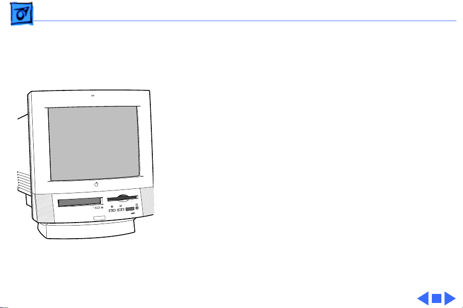
System Overview
The Power Macintosh 5200/5300 computer series
combines RISC-based PowerPC performance, full
multimedia features, and low cost in a sleek all-in-one
design.
The design includes expansion slots for 68040 LC
communications and PDS cards, as well as other video-in,
video tuner, and video-out options. Options include an IDE
hard drive in a variety of capacities and a trayloading CDROM drive.
Page 4

Basics Rev. B, 5000 Series - 2
Rev. B, 5000 Series
Apple introduced an updated 5000 series version several
months after introduction. Referred to in this manual as
“Rev. B,” the updated version incorporates design changes
that are not backward-compatible.
To determine which version you are servicing, remove the
front bezel and note the location of the speakers. If the
speakers are part of the front bezel, the unit is the original
version. To service the original version, follow the manual
for take-apart procedures and parts information, unless the
procedures specify Rev. B.
If the speakers are attached to the sides of the metal chassis,
the unit is Rev. B. To service Rev. B models, follow the
manual, substituting Rev. B procedures and parts.
Page 5

Basics Rev. B, 5000 Series - 3
Another way to identify a 5200 series version A and Rev. B
is to look at the back of the computer for the part number
and manufacture date. The label with this information is on
the lower part of the plastic case. Version A contains one of
these numbers: 620-0635 or 620-0835. Rev. B contains
one of these numbers: 620-0637 or 620-0837.
Page 6

Basics Performa 5320CD - 4
Performa 5320CD
The Performa 5320CD supersedes the 5300CD. It has a
PowerPC 603e processor running at 120 MHz and 16 MB of
RAM on the logic board. All other hardware features are the
same as the Performa 5300CD. This is an international
product not sold in the U.S.
Page 7

Basics Open Transport - 5
Open Transport
Open Transport 1.1 does not work on 5200 or 5300 Series
computers. These computers require Open Transport 1.1.1.
When version 1.1.1 is installed on these computers, a dialog
box may appear indicating that a hardware issue was
detected. This message means that Open Transport can’t be
installed until the cache/ROM DIMM is replaced.
The required repairs are covered under the Apple Repair
Extension Program. The models included in this program are
Power Macintosh 5200/75 LC and 5300/100 LC,
Macintosh Performa 5200, 5215, and 5300. Look for
repair program instructions in the REA Procedures chapter.
Page 8

Basics Service Strategy - 6
Service Strategy
Service the Power Macintosh/Performa 5000 series
through module exchange and parts replacements. Customers
can request on-site service from an Apple Authorized
Service Provider Plus (AASP+) or Apple Assurance. They
can also choose carry-in service from an Apple Authorized
Service Provider (AASP).
Ordering
AASPs planning to support the Power Macintosh/Performa
5000 series may purchase service modules and parts to
develop servicing capability. To order parts, use the
AppleOrder system, or refer to the “Service Price Pages.”
Large businesses, universities, and K-12 accounts must
provide a purchase order (PO) on all transactions, including
Page 9

Basics Service Strategy - 7
orders placed through the AppleOrder system. Service
Providers not enrolled in AppleOrder may fax their orders
to Service Provider Support (512-908-8125) or mail
them to
Apple Computer, Inc.
Service Provider Support
MS 212-SPS
Austin, TX 78714-9125
Warranty and AppleCare
These new computers are covered under the Apple One-Year
Limited Warranty. The AppleCare Service Plan is also
available. Service Providers are reimbursed for warranty
and AppleCare repairs made to these computers. For pricing
information, refer to the AppleCare section in the “Service
Price Pages.”
Page 10

Basics Service Strategy - 8
Diagnostics
Use MacTest Pro for Power Macintosh to perform
diagnostics on the Power Macintosh/Performa 5000 series.
Design for Serviceability
To access the floppy drive, CD-ROM drive, or front panel
control board, remove the drive and controls bezel. To
service the logic board, hard drive, or video options, remove
the I/O door. The logic board slides out from a connector
similar to the connector on Macintosh LC 630 and LC 500.
The CRT and degauss frame are matched at the factory and are
removed and replaced as a unit. The chassis harness is one
service module, including the metal chassis and logic board
connector with cables.
Page 11

Basics User Controls - 9
User Controls
User controls include
• Soft power-on control from keyboard
• Front-panel sound-control pushbuttons
• Front-panel brightness-control pushbuttons
• Optional infrared remote control
Page 12

Basics Internal Expansion Connections - 10
Internal Expansion Connections
Expansion connections on the logic board include
• 2 DRAM SIMM expansion slots
• LC Processor Direct Slot (PDS)
• Communications slot for modems and Ethernet
• Video-in slot for real-time video display, capture, and
overlay
• External video port
An expansion ribbon connector for an optional TV Tuner card
provides NTSC and PAL input from an external TV antenna or
cable.
Page 13

Basics Intelligent Device Electronics (IDE) Hard Drive - 11
Intelligent Device Electronics (IDE) Hard Drive
The internal hard drive uses Intelligent Device Electronics
(IDE) technology, commonly used in DOS-compatible
systems. The IDE hard drive functions the same as a typical
SCSI hard drive. You must replace IDE drives like-for-like.
The IDE drive does not affect SCSI ID selections or SCSI
termination schemes. Seven external SCSI devices may be
daisy-chained through the external SCSI port.
Page 14

Basics Processor Direct Slot (PDS) - 12
Processor Direct Slot (PDS)
The LC-PDS is compatible with the PDS in the Macintosh LC
family of computers, but it is not a true PDS. Like the
expansion slot in the other models in the Power Macintosh
and Performa 5000 series, this expansion slot supports
many PDS cards designed to operate with the MC68030 bus.
While the I/O expansion slot accepts PDS cards designed for
the Macintosh LC family of computers, some of those cards
do not work. PDS cards designed to interact with the main
processor—to provide, for example, a RAM cache or an
FPU—will not work in the I/O expansion slot.
Page 15

Basics Video-In Card - 13
Video-In Card
The Video-In Card is an optional card included with the Apple
Video System. It allows users to digitize video from the TV
Tuner, MPEG Card, and external composite or S-video
inputs. It accepts NTSC, PAL, or SECAM format video and
also provides stereo audio inputs.
Install the Video-In Card into the dedicated 60-pin, 1.75inch video slot.
Page 16

Basics MPEG Card - 14
MPEG Card
The MPEG Card is an optional card included with the Apple
MPEG Media System. The MPEG Card requires that the
Video-In Card be installed. It provides hardware
decompression for MPEG movie files, enabling full-screen
(through pixel doubling), 30-frames-per-second, 24-bit
video playback with 16-bit audio. After the MPEG movies
are compressed, they are sent to the Video-In Card, which
converts the data into digital format for output to the screen.
Install the MPEG Card in the processor direct slot.
Page 17

Basics TV Tuner Module - 15
TV Tuner Module
The TV Tuner, an optional module included with the Apple
TV/Video System, turns the computer into a television
receiver. The TV Tuner requires the Video-In Card, which is
also included with the Apple TV/Video System. The TV Tuner
receives incoming television signals from cable or antenna
television inputs, and then sends the information to the
Video-In Card, which converts the data for display on the
screen. In the United States, only NTSC is supported, but
PAL and SECAM are available internationally.
Install the TV Tuner in a separate bay at the rear of the
computer, below the logic board.
Page 18

Basics TV/FM Radio Tuner Card - 16
TV/FM Radio Tuner Card
The TV/FM radio tuner card turns the computer into a
television and FM radio receiver, complete with remote
control. An expansion ribbon connector for the optional
TV/FM radio tuner card provides NTSC and PAL input from
an external TV antenna or cable. Change channels by typing
the channel number on the keyboard or with the remote
control. Switch between the current and previous channel by
pressing the Tab key. The computer displays the userassigned channel name on the picture in the video window.
Apple Video Player software supports the TV/FM tuner card.
The user can disable channels and require a password to
access the disabled channels. Users can also capture or
freeze a single frame of video or record a segment of video as
a QuickTime movie. It isn’t possible to resize the window
while recording a movie.
Page 19

Basics TV/FM Radio Tuner Card - 17
The TV picture is in its own window on the desktop, and the
default size of the window is 320x240 pixels. The picture
can be resized from 160x120 pixels up to 640x480 pixels.
The resolution of the picture does not increase at larger
window sizes, but the image is expanded by doubling the
pixel size or by two-dimensional linear interpolation.
The TV signal is carried in YUV format for improved picture
clarity. The YUV format is 16-bit, with 8 bits for the Y
(luminance) channel and 8 bits for the U and V
(chrominance) channels to share by multiplexing. The
picture is clearer because the YUV format carries more
levels of luminance information.
Page 20

Basics TV/FM Radio Tuner Card - 18
The card is available in versions for NTSC, PAL, and SECAM
television systems. The features of the TV tuner include the
following:
• Remote tuner for 181 broadcast and cable channels (U.S.
version)
• Coaxial connector for TV antenna or cable input (F-type
connector in U.S. and Japanese version, IEC-type
connector in Europe)
• TV picture in a resizable and movable window
• YUV format for improved clarity
• Closed captioning and teletext support
• Software password protection
• Automatic and manual channel programming
• Single remote control for TV and for playback of audio
CDs
Page 21

Basics TV/FM Radio Tuner Card - 19
The features of the FM radio tuner include the following:
• FM radio frequencies received and displayed
• Stations scanned and searched up and down the frequency
spectrum
• Step frequency
• DX mode to tune out harmonic spillover from other
stations
• Stereo/mono station indicator
• Preset station programming
Page 22

Basics External Video Connector - 20
External Video Connector
The External Video Connector is an optional module that
provides the computer with video output (mirroring).
Install the External Video Connector in a dedicated
3/4-inch, 22-pin slot on the logic board.
Page 23

Basics Apple Presentation System - 21
Apple Presentation System
The Apple Presentation System (APS) is an external module
that uses the 15-pin video output connector on the
computer, and then provides a video signal for a separate
television display or for recording on a VCR. The APS
supports video mirror mode, where the image on the
television display is the same as the computer’s primary
video monitor. The APS is required for video mirroring.
Page 24

Basics CRT and Degauss Frame - 22
CRT and Degauss Frame
The CRT and degauss frames are precisely matched at the
factory and must be removed and replaced as a unit.
Page 25
Basics Front View - 23
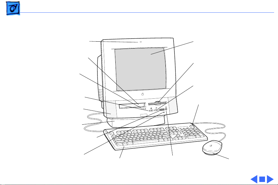
Front View
Built-In Microphone
CD-ROM Drive (optional)
CD-ROM Drive
Screen Control Buttons
Stereo Speakers
Tilt-and-Swivel Base
Remote Control Sensor
Power-On Light
Keyboard
Headphone Jack
Color Display
Floppy Disk Drive
Sound Control Buttons
Power Key
Mouse
Page 26
Basics Rear View - 24
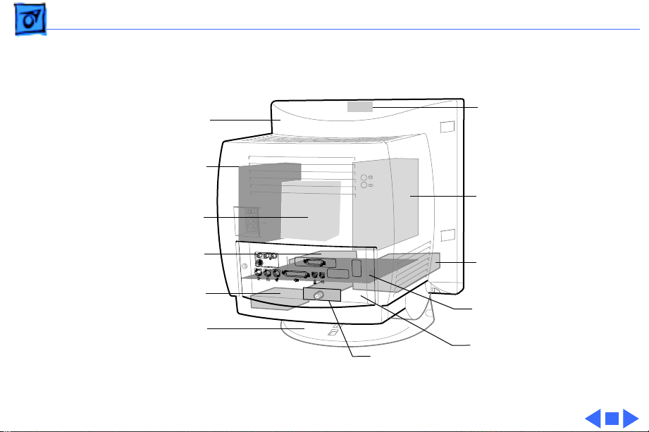
Rear View
Rear
Housing
Power
Supply
Assembly
CRT Video
Board
Assembly
Floppy
Drive
Hard
Drive
Tilt-Swivel
Assembly
TV
Tuner
Board
Microphone
Assembly
Analog
Board
Assembly
CD ROM
Drive
Logic
Board
I/O Panel
Assembly
Page 27
Basics I/O Panel - 25
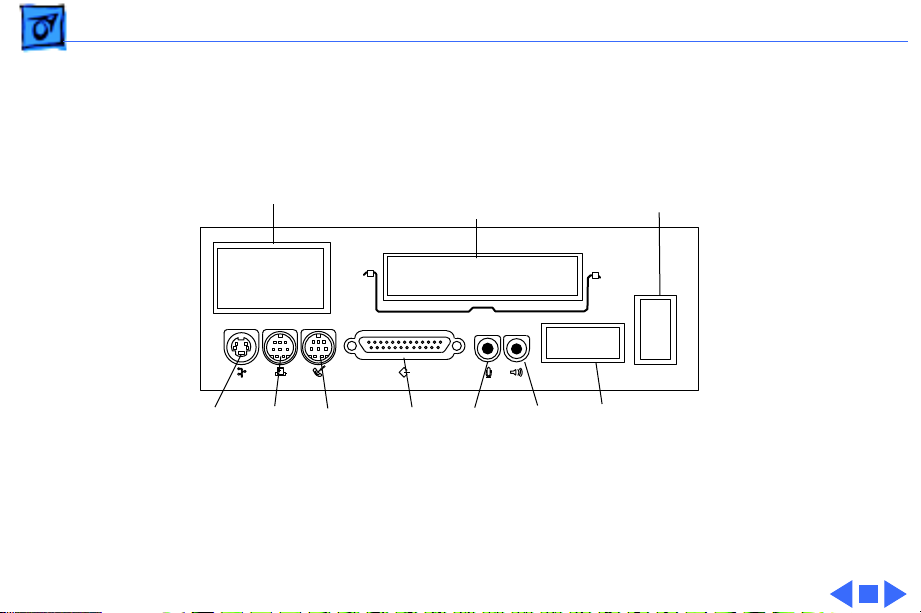
I/O Panel
Video Input
Access Cover
Printer
ADB
Port
Port
Modem
Port
External Video
Output
Connector Cover
SCSI
Sound
Port
Input
Port
Sound
Output
Port
Communication
Card Access Cover
PDS
Cover
Page 28
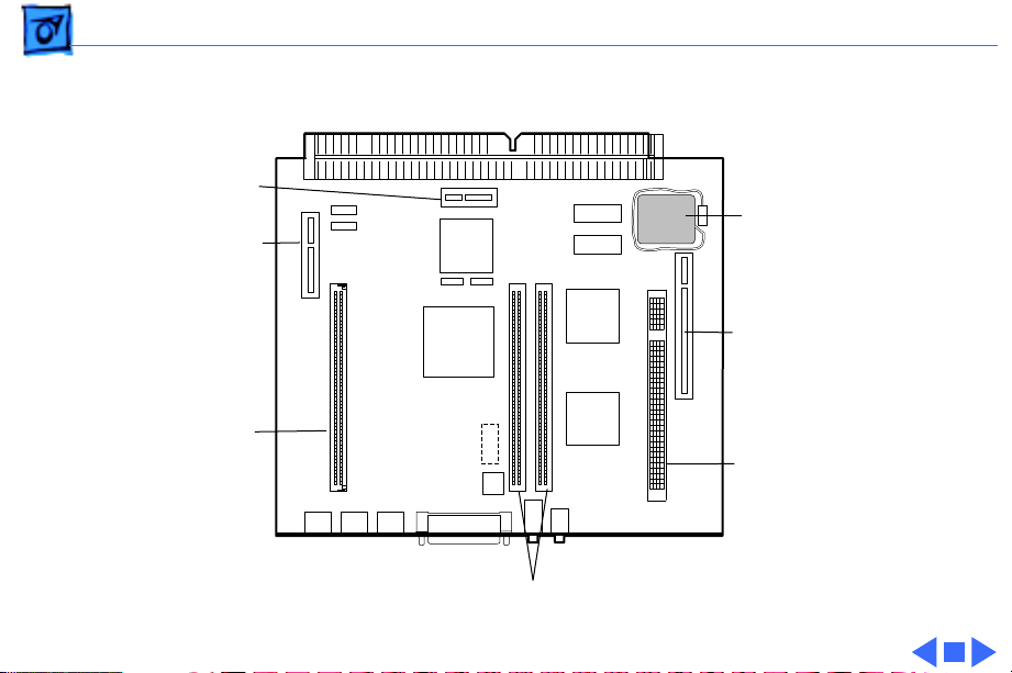
Basics 5200 Logic Board - 26
5200 Logic Board
Monitor-Out
Slot
Video-In
Slot
ROM
Slot
DRAM SIMM Slots
Battery
Communications
Card Slot
PDS
Page 29
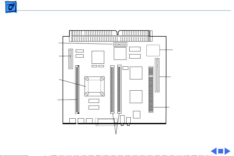
Basics 5300 Logic Board - 27
5300 Logic Board
Monitor-Out
Slot
Video-In
Slot
Battery
Processor
with
Heatsink
ROM
Slot
Communications
Card Slot
PDS
DRAM SIMM Slots
Page 30

K
Service Source
Specifications
Power Macintosh/Performa 5200
and 5300 (not 5260, 5280)
Page 31

Specifications Processor - 1
Processor
CPU
5200 Series
5300 Series (except 5320)
5320
Addressing
PowerPC 603 processor
75 MHz
PowerPC 603e processor
100 MHz
PowerPC 603e processor
120 MHz
64-bit PowerPC bus
Page 32

Specifications Memory - 2
Memory
DRAM
5200 and 5300 Series (except 5320)
5320
8 MB DRAM, minimum, in one SIMM slot
(No RAM soldered on board)
Expandable to 64 MB in two SIMM slots (72-pin, 80 ns or faster
SIMMs)
16 MB DRAM
Expandable to 64 MB in two SIMM slots (72-pin, 80 ns or faster
SIMMs)
Page 33

Specifications Memory - 3
Frame Buffer
ROM
Cache Memory
1 MB DRAM on board, for video support
4 MB
256K Level 2
Page 34

Specifications Disk Storage - 4
Disk Storage
Floppy Drive
Hard Drive
5200 Series
5300 Series
CD-ROM Drive
5200 Series
5300 Series
1.4 MB Apple SuperDrive Manual Insert
500 MB, 700 MB, or 1 GB IDE hard drive
1.2 GB IDE hard drive
Optional Apple 300i Plus CD-ROM drive
Standard AppleCD 600i drive
Page 35

Specifications I/O Interfaces - 5
I/O Interfaces
Serial
SCSI
Apple Desktop Bus
Sound Input
Two RS-232/422 serial ports for modem and printer
(mini DIN-8 connectors) LocalTalk supported
One external SCSI port (DB-25 connector)
Supports up to seven SCSI devices
One Apple Desktop Bus (ADB) port (mini DIN-4 connector)
Built-in microphone for monaural sound input.
Sound-input port for microphone or line input. The port accepts
stereophonic input, but sound is combined into monophonic
sound for play-through or recording.
Page 36

Specifications I/O Interfaces - 6
Sound Output
External Video Connector
Video-in Slot
TV Tuner
Two stereophonic sound output ports, level nominally 0.5 V RMS
into 39 ohms
One front headphone jack, one rear stereo mini phonejack
Internal stereo speakers
One DB-15 mirror video out connector using optional video
connector kit. This feature provides “mirroring” (or display
of the system’s monitor’s screen on a presentation screen).
(Note: the external video display is presentation only. It cannot
be manipulated directly by mouse or other input signals.)
One 60-pin video-in slot for optional expansion card providing
real-time video display, capture, and overlay.
One 10-pin port for TV Tuner card
Page 37

Specifications I/O Interfaces - 7
Communications
Processor-Dir ect Slot
Controls
One 112-pin internal expansion slot for modem or Ethernet card
(68040-bus configuration)
One 96/114-pin internal expansion slot for LC-compatible
processor-direct card
Soft-power control from keyboard
Front panel pushbutton control for sound volume
Front panel pushbutton control for display brightness
Infrared remote control option
Page 38

Specifications I/O Devices - 8
I/O Devices
Keyboard
Mouse
Microphone
Speaker
AppleDesign Keyboard, Apple Extended Keyboard (other ADB
keyboards supported)
Apple Desktop Bus Mouse II
Mechanical tracking, optical shaft, or contact encoding
Integrated microphone for monophonic sound input
Integrated stereo speakers capable of delivering 8-bit stereo
sound
Page 39

Specifications Sound and Video - 9
Sound and Video
Sound Generator
Records at 11-kHz or 22-kHz sample rate
Plays back at 22-kHz sample rate
Two speakers with enhanced stereo sound
Allows playback and recording of ordinary audio compact discs
(CDs)
16-bit monophonic sound input
16-bit stereophonic sound output (16-bit CD stereophonic
playback), level nominally 0.5 V RMS into 39 ohms
Sound-input port for microphone or line input; accepts
stereophonic input, but sound is combined into monophonic
sound for play-through or recording
Two stereophonic sound output ports, level nominally 0.5 V RMS
into 39 ohms
Internal speaker muted when a plug is inserted into an output jack
Page 40

Specifications Sound and Video - 10
Built-in Video Display
Dot Pitch: 0.28 mm
Vertical Frequency: 66.7 Hz
Active Raster Size (nominal): 9.5 in. by 7.3 in. (240 mm by 185
mm)
White Point: 9,300° K
Shipping Brightness (nominal): 25-foot lamberts
15-inch Shadow Mask display (12.8-inch viewable image)
Gun Configuration: Horizontal inline
Phosphor (aluminized): P22 derivative
Phosphor CIE Coordinates:
Red x = 0.625 ± 0.020, y = 0.340 ± 0.020
Green x = 0.280 ± 0.020, y = 0.595 ± 0.020
Blue x = 0.155 ± 0.015, y = 0.070 ± 0.015
Page 41

Specifications Sound and Video - 11
Video Modes
Support these video modes:
640x480 resolution with 16-bit color
800x600 resolution with 8-bit color
832x624 resolution with 8-bit color (does not support video
input)
Page 42

Specifications Sound and Video - 12
Monitor Timings 640x480 Resolution at 60 Hz
Horizontal Timing
Vertical Timing
Back Porch: 48 dots
H SYNC: 96 dots
Front Porch: 16 dots
1 dot: 39.72 ns
1 H: 31.77 ms
1/dot: 25.175 MHz
Back Porch: 33 H
V SYNC: 2 H
Front Porch: 10 H
1 H: 31.77 ms
1/H: 31.5 kHz
1V: 16.67 ms
1/V: 59.988 Hz
Page 43

Specifications Sound and Video - 13
Monitor Timings 640x480 Resolution at 66.67 Hz
Horizontal Timing
Vertical Timing
Back Porch: 96 dots
H SYNC: 64 dots
Front Porch: 64 dots
1 dot: 33.06878 n
1 H: 28.5714 ms
1/dot: 30.24 MHz
Back Porch: 39 H
V SYNC: 3 H
Front Porch: 3 H
1 H: 28.5714 ms
1/H: 35.000 kHz
1V: 15.000 ms
1/V: 66.666 Hz
Page 44

Specifications Sound and Video - 14
Monitor Timings 800x600 Resolution at 60 Hz
Horizontal Timing
Vertical Timing
Back Porch: 88 dots
H SYNC: 128 dots
Front Porch: 40 dots
1 dot: 25.000 ns
1 H: 26.4 ms
1/dot: 40.000 MHz
Back Porch: 23 H
V SYNC: 4 H
Front Porch: 1 H
1 H: 37.879 ms
1/H: 16.58 kHz
1 V: 60.3165 ms
1/V: 60.3165 Hz
Page 45

Specifications Sound and Video - 15
Monitor Timings 800x600 Resolution at 72 Hz
Horizontal Timing
Vertical Timing
Back Porch: 64 dots
H SYNC: 120 dots
Front Porch: 56 dots
1 dot: 20.000 ns
1 H: 20.800 ms
1/dot: 50.000 MHz
Back Porch: 23 H
V SYNC: 6 H
Front Porch: 37 H
1 H: 20.800 ms
1/H: 48.077 kHz
1 V: 13.853 ms
1/V: 72.186 Hz
Page 46

Specifications Sound and Video - 16
External Video Connector (Optional)
Supports video mirroring on the following external monitors (at
product introduction):
• 640x480 resolution: Macintosh 12-inch Color Display, Apple
Color Plus 14-inch Display, Apple Performa Plus Display,
Apple Multiple Scan 15 Display, Apple Multiple Scan 17
Display, Apple Multiple Scan 20 Display
• 800x600 resolution: Apple Multiple Scan 15 Display, Apple
Multiple Scan 17 Display, Apple Multiple Scan 20 Display, and
SVGA monitors
Page 47

Specifications Electrical - 17
Electrical
Line V oltage
Frequency
Power
100–240 VAC
47–63 Hz
125 W
Surge Voltage: 300 V rms for 100 ms
Peak Inrush Current: 40 A pk
Current: 2.5 A maximum for all line and load conditions
Power: 220 W maximum for all line and load conditions
Page 48

Specifications Physical - 18
Physical
Dimensions
Weight
Height: 17.5" (445 mm)
Width: 16" (406 mm)
Depth: 15.1" (383 mm)
Without CD-ROM: 17 lb.
With CD-ROM: 19 lb. (21.15 kg)
Weight varies with options
Page 49

Specifications Environmental - 19
Environmental
Temperature
Humidity
Altitude
Operating: 50°–104° F (10°–40° C)
Transit (72 hours): –40° F to +149° F (–40° C to +65° C)
Storage (6 months): –40° F to +116° F (–40° C to +47° C)
Noncondensing, 20–95%
0–10,000 ft. (0–3,000 m)
Page 50

K
Service Source
Troubleshooting
Power Macintosh/Performa
5200 and 5300 (not 5260, 5280)
Page 51

Troubleshooting General - 1
General
The Symptom Charts included in this chapter will help you
diagnose specific symptoms related to your product. Because cures
are listed on the charts in the order of most likely solution, try
the first cure first. Verify whether the product continues to
exhibit the symptom. If the symptom persists, try the next cure.
(
Note:
If you have replaced a module, reinstall the original
module before you proceed to the next cure.)
If you are not sure what the problem is, or if the Symptom Charts
do not resolve the problem, refer to the Flowchart for the product
family.
For additional assistance, contact Apple Technical Support.
Page 52

Troubleshooting First Checklist - 2
First Checklist
Jitter, faint lines, or screen movement can be caused by external
interference such as electronic devices and fluorescent lights.
Move the unit to another room or building to help determine if
external interference is the source of the problem.
A misadjusted screen can mimic the same symptoms as analog
board or CRT failures. By performing the adjustment procedures,
you might determine if one or more of the adjustments is the cause
of the problem.
Page 53

Troubleshooting Symptom Charts/System - 3
Symptom Charts
System
System
intermittently
crashes or hangs
1 Verify that system software is version 7.5 or later.
2 Verify that software is compatible with system.
3 If clock chip at U10 is not p/n 343S1191 or 343S1121,
replace logic board. (Ignore any letters following part
number.)
4 If ROM DIMM is laid out as shown on next page, and doesn’t
have a sticker on center chip, replace DIMM.
5 If Ethernet card is installed, verify that it is fully seated.
6 Check that system has enough memory installed for
application.
Page 54

Troubleshooting Symptom Charts/System - 4
No Sticker
ROM DIMM
Chip at
U10
Logic Board
Figure 1: ROM DIMM
Page 55

Troubleshooting Symptom Charts/System - 5
System does not start
up
System will not start
up from keyboard,
but will start up from
rear power switch
System continually
restarts after
Shutdown from
Special menu
1 Reset logic board. Refer to Additional Procedures.
2 Replace power supply.
3 Check power cord connection.
4 Replace logic board. Retain customer’s SIMMs.
1 Verify keyboard as known-good.
2 Replace analog board.
1 Verify keyboard as known-good.
2 Replace analog board.
Page 56

Troubleshooting Symptom Charts/System - 6
Flashing “?”
appears at startup in
system with vacant
PDS and
communications slots
Flashing “?”
appears at startup in
system with version
B logic board and
card in PDS or
communications
slot
1 Diagnose hard drive with Disk First Aid included on Power
Macintosh CD-ROM.
2 Perform repairs, and then go to step 4.
3 If repairs are impossible, back up drive, reformat with
Drive Setup 1.0.3, and then go to step 4.
4 Update driver using Drive Setup 1.0.3.
5 Perform clean install of system software.
Note:
Version “B” logic boards display a “B” at the end of the
serial number printed on the board near the communications
port. (See figure on the next page.)
1 Verify that system software is version 7.5 or later.
2 If chip at logic board location U6 does not include picture of
Texas and is p/n 343S0138-a, and there is no wire at U27
on underside of board, replace logic board.
Page 57

Troubleshooting Symptom Charts/System - 7
.
Apple Computer
Inc. @199X
XXX-XXXX-B
Apple Computer
Inc. @199X
XXX-XXXX-B
No Picture
of Texas
Part No.
U6
343S0138-a
Figure 2: Identifying Version B Logic Boards
Page 58

Troubleshooting Symptom Charts/System - 8
Menu bar constantly
flashes or system
constantly beeps
System shuts down
when Restart chosen
from Special Menu.
1 Verify that front-panel control buttons are not jammed.
2 Verify “mute” is not selected in the Sound control panel.
3 Reseat drive bezel and front-panel control board.
Replace analog board.
Page 59

Troubleshooting Symptom Charts/Audio - 9
Audio
Distorted or garbled
sound from both
speakers
Distorted or garbled
sound from one
speaker
Sound distortion
with MPEG board
installed
No sound output from
speakers
Replace analog/video board assembly.
1 Replace defective speaker.
2 Replace analog/video board assembly.
Replace MPEG board with modified MPEG board. A modified
board should have a jumper present from U5 Pin 2 to D1 Pin 1.
1 Check sound source.
2 Check that speaker cable at connector P803 on analog board
is plugged in and not defective.
3 Reseat drive bezel and front-panel control board.
Page 60

Troubleshooting Symptom Charts/Audio - 10
Crackling noise is
present when
playing sounds other
than system beeps
and not in “play
through” mode
1 If static noise varies while adjusting volume with Sound
control panel, use Audio Volume Extension 1.1 or later.
Note:
Audio Volume Extension is available from standard
Apple software update sites.
2 Replace logic board.
Page 61

Troubleshooting Symptom Charts/Video - 11
Video
Screen is black, too
dark, or too bright;
audio and drive
operate
Screen is bright and
audio is present, but
no video information
is visible
1 Adjust contrast button on front bezel.
2 Adjust brightness. Use Screen control panel.
3 Check yoke cable connection.
4 Perform video adjustments. Refer to “Video” in
Adjustments chapter.
5 Replace analog/video board assembly.
6 Replace power supply board.
7 Replace CRT.
1 Perform video adjustments. Refer to “Video” in
Adjustments chapter.
2 Replace analog/video board assembly.
Page 62

Troubleshooting Symptom Charts/Video - 12
Video will not play
or system hangs
when attempting to
run video in units
with MPEG card
Single vertical or
horizontal line is
displayed
Predominant color
tint or color cannot
be adjusted
1 If chip at location U12 on MPEG card displays number
341SO205, check all connections.
2 If chip at location U12 on MPEG card does not display
number 341SO205, replace MPEG card.
1 Replace analog/video board assembly.
2 Replace CRT.
1 Verify that video board is securely connected to CRT
socket.
2 Check cable connections to analog/video board.
3 If analog/video board is Rev A, replace internal RGB cable.
4 Replace analog/video board assembly. Perform video
adjustments (refer to “Video” in Adjustments chapter).
5 Replace CRT.
Page 63

Troubleshooting Symptom Charts/Video - 13
Picture breaks into
diagonal lines, or
picture rolls
vertically or
horizontally
Out of convergence
(color bleeds from
text or lines)
Black screen spots
(burnt phosphors)
1 Perform geometry adjustments. Refer to “Geometry” in
Adjustments chapter.
2 Replace analog/video board assembly.
1 This problem rarely indicates a defective module. Some
misconvergence is normal, especially around edges of screen.
Contact Apple Technical Support if you’re uncertain whether
misconvergence is within specification.
2 Replace analog/video board assembly.
Replace CRT.
Page 64

Troubleshooting Symptom Charts/Video - 14
Screen jitters or
flashes
Out of focus 1 Perform focus adjustment. Refer to “Focus” in Adjustments
1 Refer to “First Checklist” in Troubleshooting chapter. Move
electrical devices (other monitors, scanners, and so on)
away from monitor. Temporarily shut off all fluorescent
lights in area.
2 Move unit to another room or building and check if symptom
persists.
3 Replace analog/video board assembly.
chapter.
2 Check for proper screen luminance. If luminance is off,
perform Cutoff and White Balance procedures. Refer to
“Video” in Adjustments chapter.
3 Replace analog/video board assembly.
Page 65

Troubleshooting Symptom Charts/Video - 15
Raster size too short/
tall or narrow/wide
Linearity bad (size of
text/graphics differs
at top, bottom, or
sides of screen)
Raster tilted or
shifted
Install monitor adjustment cable, and set appropriate on-screen
video adjustment controls to vertical height of 185 mm (7.3
inches) and to horizontal width of 240 mm (9.5 inches).
Replace analog/video board assembly.
1 Refer to “First Checklist” in Troubleshooting chapter. Move
metal objects away from monitor.
2 Perform appropriate geometric adjustments. Refer to
“Geometry” in Adjustments chapter.
3 Replace analog/video board assembly.
Page 66

Troubleshooting Symptom Charts/Video - 16
Raster distorted
(barrel-shaped,
corners not square,
stretched or
compressed at top of
display, or sides not
perpendicular)
Raster not centered 1 Adjust horizontal or vertical shift control. Refer to
1 Refer to “First Checklist” in Troubleshooting chapter.
2 Perform appropriate geometric adjustments. Refer to
“Geometry” in Adjustments chapter.
3 Install monitor-adjustment cable and use on-screen video
adjustment controls to eliminate distortion. Based on video
tolerances, some distortion is allowed and setting need not be
perfect. Contact Apple Technical Support if you’re unsure
about tolerance level.
4 Replace analog/video board assembly.
Adjustments chapter.
2 Refer to “First Checklist” in Troubleshooting chapter.
3 Install monitor-adjustment cable and use on-screen video
adjustment controls to center raster. If centering range is
insufficient, change the setting of switch SW701
(three-position switch).
Page 67

Troubleshooting Symptom Charts/Video - 17
Screen has white
areas with blotches of
color
1 Refer to “First Checklist” in Troubleshooting chapter.
2 Because this purity problem can be caused by magnetic
fields, move unit to another location.
3 Degauss display with manual degaussing coil. (Degaussing
coils can be purchased at most major electronic parts
stores.)
Page 68

Troubleshooting Symptom Charts/Floppy Drive - 18
Floppy Drive
Audio and video are
present, but internal
floppy drive does not
operate
Disk ejects; display
shows icon with
blinking “X”
Unable to insert disk
all the way
1 Replace bad disk with known-good disk.
2 Replace floppy drive.
3 Replace logic board. Retain customer’s SIMMs.
1 Replace bad system disk with known-good system disk.
2 Replace floppy drive.
3 Replace logic board. Retain customer’s SIMMs.
1 To eject previously inserted disk, insert opened paper clip
into hole beside floppy drive.
2 Switch off system and hold mouse button down while
switching system on (to complete eject cycle).
3 Replace floppy drive.
Page 69

Troubleshooting Symptom Charts/Floppy Drive - 19
Disk does not eject 1 Insert opened paper clip into hole beside floppy drive.
2 Switch off system and hold mouse button down while
switching system on (to complete eject cycle).
3 Replace floppy drive.
Internal floppy drive
runs continuously
1 Replace bad disk with known-good disk.
2 Replace floppy drive.
3 Replace logic board. Retain customer’s SIMMs.
Page 70

Troubleshooting Symptom Charts/Hard Drive - 20
Hard Drive
Internal or external
hard drive does not
operate
Internal hard drive
runs continuously
Hard drive not found
when booted from CDROM drive
1 Verify that all hard drive connections are secure.
2 Verify that external drive is properly terminated.
3 Reseat logic board.
4 Replace internal IDE hard drive.
5 Replace chassis/wiring harness.
6 Replace logic board. Retain customer’s SIMMs.
1 Verify that system software is version 7.5 (or later).
2 Replace hard drive cable.
3 Replace internal hard drive.
4 Replace logic board. Retain customer’s SIMMs.
Use Drive Setup 1.03 to attempt mounting the hard drive.
Page 71

Troubleshooting Symptom Charts/CD-ROM Drive - 21
CD-ROM Drive
CD-ROM drive does
not accept disc
Volume control does
not operate correctly
1 Exchange compact disc (if disc is dirty or damaged).
2 Replace CD-ROM drive mechanism.
3 Replace SCSI data cable.
1 Check Sound control panel setting.
2 Check front-panel controls.
3 Reseat the drive and control bezel.
4 Verify that the front-panel control board is completely
installed.
5 Reseat CD adapter connector.
6 Replace CD adapter connector.
7 Replace CD-ROM drive.
8 Replace chassis/wiring harness.
Page 72

Troubleshooting Symptom Charts/CD-ROM Drive - 22
Computer cannot
mount known-good
CD-ROM drive
When an internal and
external SCSI device
are present, only one
starts up
CD Plus (CD+)
format CD-ROM disc
causes stuttering
sound, and may not
mount.
1 Reseat CD-ROM drive adapters.
2 Check SCSI ID setting. (Internal CD-ROM drive was
originally set to 3 at factory.)
3 Replace CD-ROM drive.
4 Replace chassis/wiring harness
1 Verify that ID switch setting on external SCSI device is
higher than 0. Verify that ID switch setting on external SCSI
device does not duplicate ID switch settings on other external
SCSI devices.
2 Replace terminator on external SCSI device.
3 Replace SCSI select cable.
Replace CD-ROM drive.
Page 73

Troubleshooting Symptom Charts/CD-ROM Drive - 23
Eject button sticks. Replace the front bezel (P/N 922-1398 Rev. A or P/N 922-
1857 Rev. B).
Page 74

Troubleshooting Symptom Charts/Peripheral - 24
Peripheral
Cursor does not move 1 Restart system.
2 Check mouse connection.
3 If mouse was connected to keyboard, connect mouse to rear
ADB port and disconnect keyboard. If mouse works, replace
keyboard. If mouse does not work in ADB port, replace mouse.
4 Reseat logic board.
5 Replace logic board. Retain customer’s SIMMs.
Cursor moves, but
clicking mouse
button has no effect
1 Replace mouse.
2 Reseat logic board.
3 Replace logic board. Retain customer’s SIMMs.
Page 75

Troubleshooting Symptom Charts/Peripheral - 25
Cannot double-click
to open application,
disk, or server
No response to any
key on keyboard
1 Remove extra system files on hard drive.
2 Check mouse speed on Control Panel.
3 Unplug 4.5 battery, wait 20 seconds, plug in battery, and
restart computer.
4 If mouse was connected to keyboard, connect mouse to rear
ADB port and disconnect keyboard. If mouse works, replace
keyboard. If mouse does not work in ADB port, replace mouse.
5 Replace logic board. Retain customer’s SIMMs.
1 Verify that system software is version 7.5 (or later).
2 Check keyboard connection to ADB port.
3 Replace keyboard.
4 Reseat logic board.
5 Replace logic board. Retain customer’s SIMMs.
Page 76

Troubleshooting Symptom Charts/Peripheral - 26
Known-good
StyleWriter,
ImageWriter, or
ImageWriter II does
not print
Known-good
LaserWriter does not
print
Doesn’t recognize
SCSI device
1 Verify that Chooser and Control Panel are set correctly.
2 Verify that printer driver and system software are not
corrupt.
3 Verify system software is version 7.5 (or later).
4 Check printer DIP switches.
5 Replace printer interface cable.
6 Replace logic board. Retain customer’s SIMMs.
1 Verify that Chooser and Control Panel are set correctly.
2 Verify that printer driver and system software are not
corrupt.
3 Replace printer interface cable(s).
1 Check for proper SCSI termination.
2 Check that the SCSI cable is good and firmly connected.
3 Check the SCSI device manual for required software.
Page 77

Troubleshooting Symptom Charts/Miscellaneous - 27
Miscellaneous
Clicking, chirping,
or thumping sound
Smoke or Odor
Present
No video, no audio, and
no drive operation
1 Replace analog board.
2 Replace logic board. Retain customer’s SIMMs.
1 Replace Analog board.
2 Replace Power Supply.
3 Replace Logic Board.
1 Connect power cord.
2 Switch power on.
3 Replace power cord.
4 Replace analog board.
5 Replace logic board. Retain customer’s SIMMs.
Page 78

Troubleshooting Symptom Charts/Miscellaneous - 28
Screen shows “Sad
Macintosh” icon and
black vertical lines;
screeching sound
Rattling sound at
startup in system
with Apple External
Video Connector
Headphone jack does
not operate correctly
1 Replace RAM SIMMs on logic board.
2 Replace logic board. Retain customer’s SIMMs.
Press or fold Apple External Video cable to prevent it from
contacting fan blades.
1 Verify that headphone jack is seated properly.
2 Replace front panel control board.
3 Replace chassis/wiring harness.
Page 79

Troubleshooting Symptom Charts/Miscellaneous - 29
“Sad Macintosh” icon 1 Verify that no disc is in CD-ROM drive.
2 Disconnect all external SCSI devices and attempt to restart
computer.
3 Disconnect internal SCSI device and attempt to start
computer with known-good floppy disk.
4 Replace bad SCSI drive with known-good SCSI drive.
5 Replace RAM SIMM on logic board.
6 Replace logic board. Retain customer’s SIMMs.
No sound from
known-good external
speakers
1 Check that volume is turned on (manually or through Control
Panel).
2 Verify that headphones are unplugged.
3 Verify that speaker connectors are properly connected.
4 Replace logic board. Retain customer’s SIMMs.
Page 80

Troubleshooting Symptom Charts/Miscellaneous - 30
System with internal
modem unable to
recognize graphics or
Ethernet card in
communications slot
1 Replace internal modem.
2 Replace graphics or Ethernet card.
Page 81

Troubleshooting Symptom Charts/Global Village Modem “Busy Serial Port” - 31
Global Village Modem “Busy Serial Port”
Using modem gives
message: “Can’t find
or can’t access a
modem to use for
registration. Make
sure you have Global
Village software
installed correctly,
reboot your
computer, and try
again. If you want to
use a specific modem
for registration,
select it from
Chooser.”
The TelePort Control Panel becomes corrupted when a Performa
5200CD is restarted while AppleTalk is set to “Inactive” in the
Chooser or LocalTalk is not the selected AppleTalk Connection in
the Network Control Panel. Follow these steps;
1 Obtain GlobalFax 2.5.2P Update.
2 Restart the computer with extensions off.
3 Double-click Performa GlobalFax 2.5.2 Update icon.
4 Click Update button and watch for update confirmation
window.
5 Restart computer.
6 Customer should keep backup copy of 2.5.2 Update program
and run it after reinstalling software from backup CD.
Page 82

Troubleshooting Symptom Charts/Global Village Modem “Busy Serial Port” - 32
Resetting modem in
TelePort Control
Panel gives message:
“The current port is
busy and cannot be
opened. Quit any open
communication
application, or turn
off AppleTalk in the
Chooser (if the
modem is connected to
the Printer port),
and then reopen the
TelePort control
panel.”
Here’s an alternative fix that doesn’t require GlobalFax 2.5.2P
Update:
1 Replace corrupted control panel in System Folder with
uncorrupted copy of TelePort Control Panel found in Control
Panels folder on backup CDs.
2 Set AppleTalk to “Active” and select LocalTalk as the
AppleTalk Connection in Network Control Panel.
Page 83

K
Service Source
Take Apart
Power Macintosh/Performa
5200 and 5300 (not 5260, 5280)
Page 84

Take Apart Drive and Control Bezel - 1
Drive and Control Bezel
No preliminary steps are
required before you begin
this procedure.
Page 85

Take Apart Drive and Control Bezel - 2
1 Placing your fingertips
in the holes of the finger
latches, pull the two
finger latches down.
2 Swing the drive and
control bezel up and off.
Page 86

Take Apart Drive and Control Bezel - 3
Replacement Note:
Insert the drive bezel hinge
tabs behind the upper
corners of the front bezel
opening. Swing the drive
bezel down until it snaps
closed.
Page 87

Take Apart Floppy Drive - 4
Floppy Drive
Before you begin, remove
the drive and control bezel.
Caution:
precautions in Bulletins/
Safety.
Review the ESD
Page 88

Take Apart Floppy Drive - 5
1 Pull up the release
latch, and pull out the
floppy drive far enough
to reach the ribbon cable
connector.
Page 89

Take Apart Floppy Drive - 6
2 Disconnect the floppy
drive from the floppy
drive cable.
Note:
Remove the drive
carrier if you are replacing
the floppy drive.
Note:
Because screw
placement varies according
to the type of drive used with
the carrier, note the
placement of the screws
before removing them.
Retain the carrier and
screws, and install them on
the new floppy drive.
Page 90

Take Apart Floppy Drive - 7
3 Remove the four
mounting screws.
4 Remove the carrier from
the floppy drive.
Page 91

Take Apart CD-ROM Drive - 8
CD-ROM Drive
Before you begin, remove
the following:
• Drive and control bezel
• Floppy drive
Note:
The CD-ROM drive is
optional.
Caution:
precautions in Bulletins/
Safety.
Review the ESD
Page 92

Take Apart CD-ROM Drive - 9
Push up the release latch
and pull the CD-ROM drive
from the chassis.
Note:
You may need to use
some initial force to
disconnect the CD-ROM
drive from the internal
chassis/wiring harness.
Page 93

Take Apart CD-ROM Drive - 10
Note:
Perform the
following steps only if you
are replacing the CD-ROM
drive.
1 Disconnect the CD-ROM
audio adapter from the
drive.
2 Disconnect the SCSI
adapter.
3 Remove the four
mounting screws and
carrier from the CDROM drive.
Page 94

Take Apart CD-ROM Drive - 11
Replacement Note:
Retain the carrier, screws,
and adapters for installation
on the new drive.
Replacement Caution:
Before replacing the SCSI
adapter, verify that the SCSI
drive connector pins are not
bent.
Page 95

Take Apart Front Panel Control Board - 12
Front Panel Control Board
Before you begin, remove
the drive and control bezel.
Caution:
precautions in Bulletins/
Safety.
Review the ESD
Page 96

Take Apart Front Panel Control Board - 13
Caution:
Be sure to grip
the front panel in the area
shown to avoid harming
circuit tracings.
1 Using needle-nose
pliers, grip the front
edge of the front-panel
control board.
2 Pull firmly and slide the
front panel control board
out far enough to reach
the ribbon cable
connector.
Page 97

Take Apart Front Panel Control Board - 14
3 Disconnect the cable
from the front-panel
control board.
Replacement Note:
Using
a flat-blade screwdriver,
press the front-panel
control cable back and down.
Page 98

Take Apart Front Panel Control Board - 15
Replacement Note:
the board up slightly to
insert it into the guide rails.
Tilt
Page 99

Take Apart Front Panel Control Board - 16
Replacement Note:
front edge of the reinstalled
front-panel control board
must be flush with the front
edge of the plastic chassis.
The
Page 100

Take Apart I/O Door - 17
I/O Door
No preliminary steps are
required before you begin
this procedure.
 Loading...