

Apple Macintosh Color Display Service Manual
K
Service Source
Macintosh Color Display
K
Service Source
Specifications
Macintosh Color Display

Specifications Characteristics - 1
Characteristics
Picture Tube
Screen Resolution
Scan Rates
Active V ideo Display Area
14-in. diagonal (11.5-in. viewable image)
Trinitron CRT with high-contrast glass
.26-mm aperture grille pitch
640x480
70 dpi
Horizontal scan rate: 35.0 KHz
Vertical refresh rate: 66.7 Hz
9.3 in. by 6.9 in.
(235 mm by 176 mm)

Specifications Characteristics - 2
Input Signals
Red, green, and blue analog signals
Separate synchronization, negative-going TTL

Specifications Controls and Ports - 3
Controls and Ports
User Controls
Front panel: brightness and contrast controls, power switch

Specifications Physical and Electrical - 4
Physical and Electrical
Power Supply
Fuse Protection
Size and Weight
Universal power supply
Voltage: 90–270 VAC
Frequency: 47–63 Hz
Power: 37 W normal, 55 W maximum
Internal power-line fuse protection (qualified service technician
is required to replace the fuse)
Height: 13 in. (330 mm)
Width: 13.5 in. (344 mm)
Depth: 15.5 in. (394 mm)
Weight: 24 lb. 14 oz. (11.3 kg), including video and power cables

Specifications Physical and Electrical - 5
W arm-Up Time
20 minutes required to meet all specifications

Specifications Operating Environment - 6
Operating Environment
Temperature
Humidity
50°–95°F (10°–40°C)
95% maximum, noncondensing
K
Service Source
Troubleshooting
Macintosh Color Display

Troubleshooting General/ - 1
General
The Symptom Charts included in this chapter will help you
diagnose specific symptoms related to your product. Because cures
are listed on the charts in the order of most likely solution, try
the first cure first. Verify whether or not the product continues to
exhibit the symptom. If the symptom persists, try the next cure.
(Note: If you have replaced a module, reinstall the original module
before you proceed to the next cure.)
If you are not sure what the problem is, or if the Symptom Charts
do not resolve the problem, refer to the Flowchart for the product
family.
For additional assistance, contact Apple Technical Support.

Troubleshooting Symptom Charts/No Raster - 2
Symptom Charts
No Raster
No raster, LED off 1 Check power cable connections and power switch.
2 Check all connections on main board.
3 Replace blown fuse.
4 Replace main board.
No raster, LED on,
CRT filament on
1 Adjust contrast and brightness knobs.
2 Connect known-good monitor and verify that built-in video
signal or video card is working properly.
3 Check all connections on main board. Make sure video
connector is secure and wires are inside plastic connector.
4 Perform video adjustments. Refer to “Video” in Adjustments
chapter.
5 Replace main board.
6 Replace CRT.

Troubleshooting Symptom Charts/Geometry - 3
Geometry
Raster too short, tall,
narrow, or wide
Raster not centered 1 Move unit away from monitors, fluorescent lights, or other
Horizontal linearity
bad (size of text
differs at sides of
screen)
1 Adjust vertical or horizontal size controls. Refer to
“Geometry” in Adjustments chapter.
2 Replace main board.
electrical equipment.
2 Adjust vertical or horizontal center controls. Refer to
“Geometry” in Adjustments chapter.
3 Replace main board.
Replace main board.

Troubleshooting Symptom Charts/Geometry
(Continued)
- 4
Vertical linearity bad
(size of text differs at
top vs. bottom of
screen)
Abnormal or
distorted raster
Geometry
Replace main board.
1 Move unit away from monitors, fluorescent lights, or other
electrical equipment.
2 Perform geometry adjustments. Refer to “Geometry” in
Adjustments chapter.
3 Replace main board.
4 Replace CRT (rarely required).
(Continued)

Troubleshooting Symptom Charts/Geometry
(Continued)
- 5
Geometry
Entire raster is tilted 1 Move unit away from monitors, fluorescent lights, or other
electrical equipment.
2 Perform geometry adjustments. Refer to “Geometry” in
Adjustments chapter.
3 Perform yoke adjustments. Refer to “Yoke” in Adjustments
chapter.
4 Replace main board.
(Continued)
Troubleshooting Symptom Charts/Synchronization - 6
Synchronization
Picture breaks into
diagonal lines
Picture rolls
vertically
Picture breaks and
rolls horizontally
1 Connect known-good monitor and verify that built-in video
signal or video card is working properly.
2 Replace main board.
1 Connect known-good monitor and verify that built-in video
signal or video card is working properly.
2 Replace main board.
1 Connect known-good monitor and verify that built-in video
signal or video card is working properly.
2 Replace main board.

Troubleshooting Symptom Charts/Synchronization
(Continued)
- 7
Black raster with
single vertical or
horizontal line
Synchronization
1 Replace main board.
2 Replace CRT.
(Continued)

Troubleshooting Symptom Charts/Video - 8
Video
Raster too dark, too
bright, or washed out
Out of focus 1 Perform focus adjustment. Refer to “Video” in Adjustments
1 Adjust external contrast and brightness controls.
2 Connect known-good monitor and verify that built-in video
signal or video card is working properly.
3 Perform video adjustments. Refer to “Video” in Adjustments
chapter.
4 Replace main board.
5 Replace CRT (rarely required).
chapter.
2 Replace main board.
3 Adjust focus controls to their limits. If bad focus remains on
one part of display, replace CRT.

Troubleshooting Symptom Charts/Video
(Continued)
- 9
Predominant color
tint
Out of convergence
(color bleeding out
from text or lines)
Video
1 Check video card in computer.
2 Perform video adjustments. Refer to “Video” in Adjustments
3 Replace main board.
4 Replace CRT (if you cannot eliminate red, green, or blue
1 Connect known-good monitor and verify that built-in video
2 Perform convergence adjustments. Refer to “Video” in
3 Replace main board.
4 Replace CRT.
(Continued)
chapter.
tint).
signal or video card is working properly.
Adjustments chapter.

Troubleshooting Symptom Charts/Miscellaneous - 10
Miscellaneous
Picture jitters or
flashes
Intermittently shuts
down
Flashing or wavy
screen
Black screen spots
(burnt phosphors)
1 Move unit away from monitors, fluorescent lights, or other
electrical equipment.
2 Check that all ground cables are secure.
3 Replace main board.
Replace main board.
Replace main board.
Replace CRT.

Troubleshooting Symptom Charts/Miscellaneous
(Continued)
- 11
Miscellaneous
Monitor emits highpitched noise
Does not degauss Replace main board.
Erratic or no
communication with
ADB device
Thin horizontal line
on screen
Replace main board.
Replace keyboard cable, keyboard, mouse, or other ADB device.
Displays smaller than 15 inches with tron-style CRTs typically
have a single horizontal grid wire about one-third of the way from
the bottom of the display image. This supporting wire, which is
thinner than a human hair, stabilizes the aperture grill against
shocks. The line is common to all tron-style displays and is not a
screen defect. It cannot be adjusted out or eliminated by repairing
or replacing display modules.
(Continued)
K
Service Source
T ak e Apart
Macintosh Color Display
Take Apart Rear Cover - 1
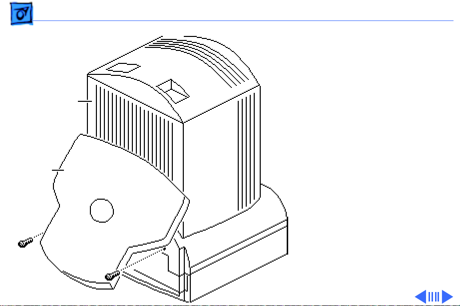
Rear Cover
No preliminary steps are
required before you begin
Rear Cover
Base
this procedure.
1 With the monitor face-
down on a protective pad,
swivel the base to access
the two case screws.
2 Remove the two screws.
Take Apart Rear Cover - 2
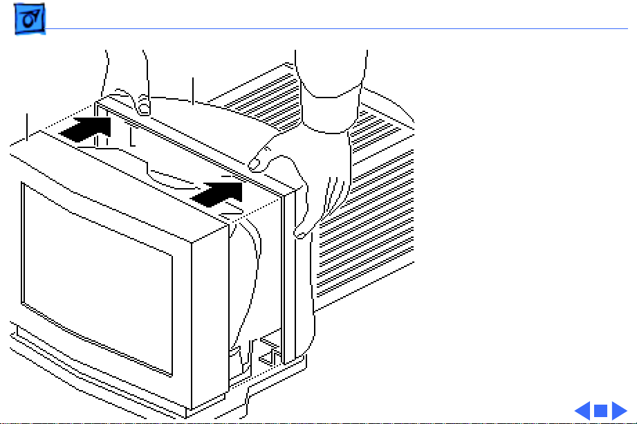
Bezel
Rear Cover
Tab
Tab
3 Set the monitor upright.
4 Press down on the top of
the rear cover to
release the two tabs
from the bezel.
5 Lift the rear cover off
the bezel.
Take Apart Base Assembly - 3
Base Assembly
Before you begin,
• Remove the rear cover
• Discharge the CRT
±
Warning:
contains high voltage and a
high-vacuum picture tube.
To prevent serious injury,
review CRT safety in
Bulletins/Safety.
±
Warning:
grounding wriststrap until
after discharging the CRT.
This product
Never use a
Base Assembly
Ê
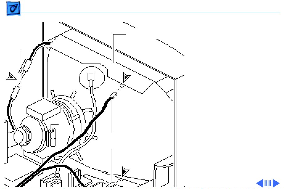
Take Apart Base Assembly - 4
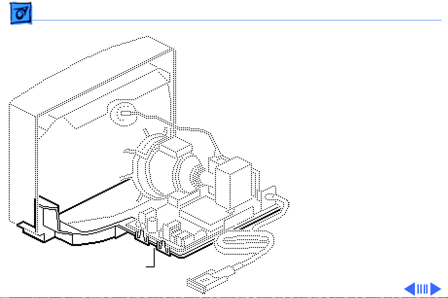
1 Cut the tie wrap and
Degauss Panel
Two-Wire
Connector
disconnect these cables:
• Two ground cables
from the degauss
panels
• Two-wire (black/
white) cable
Tie
Wrap
Ground
Cables
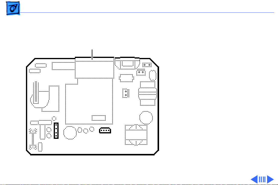
Take Apart Base Assembly - 5
2 Disconnect these cables:
• Yoke cable (4-wire/
Main Board
4-pin) from BD1
• Contrast/brightness
cable (4-wire/4pin) from BV4
BD1
BV4
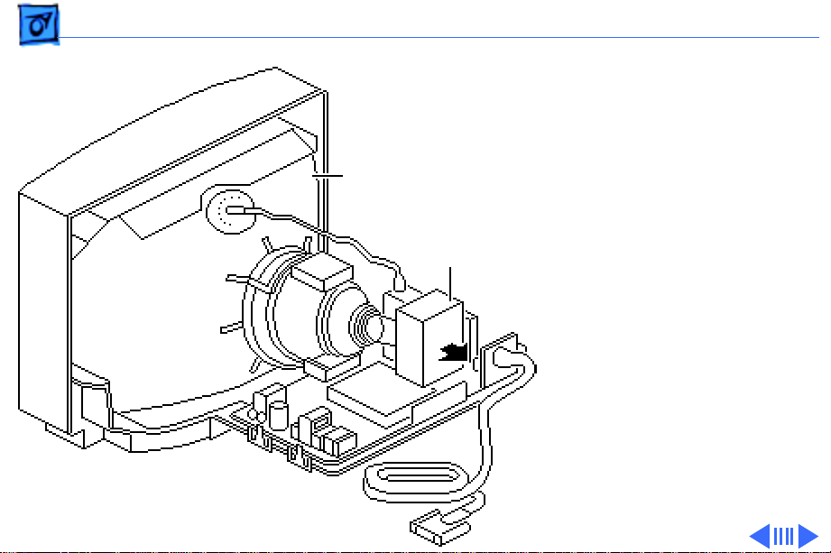
Take Apart Base Assembly - 6
CRT
Video Board
Assembly
Caution:
Twisting,
bending, or applying
force to the video board
assembly could damage
the neck of the CRT. Be
sure to pull the CRT/
video board straight off
the CRT.
3 Remove the video board
assembly from the neck
of the CRT.
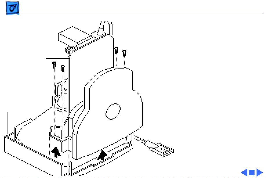
Take Apart Base Assembly - 7
4 With the monitor face
down, remove the four
Torx screws that secure
the base assembly to the
Base Assembly
bezel.
5 Lift the base assembly
off the bezel.
Bezel
Replacement Note:
The
bottom degauss panel
remains on the base
assembly. If you are
replacing the base
assembly, remove the
bottom degauss panel
and reinstall it on the
new base assembly.
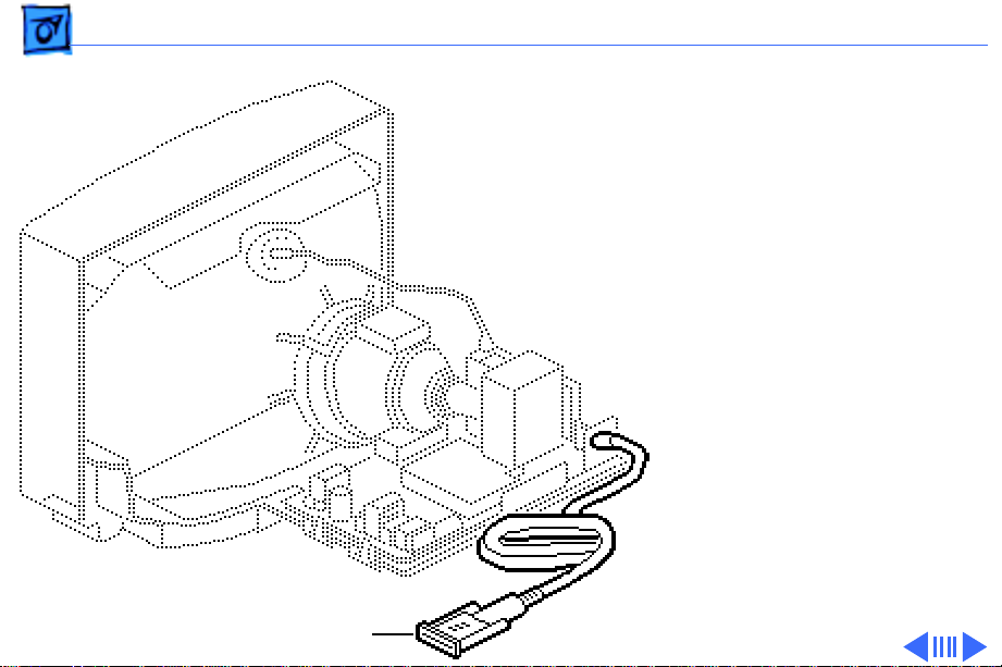
Take Apart Video Cable - 8
Video Cable
Before you begin,
• Remove the rear cover
• Discharge the CRT
±
Video Cable
Warning:
contains high voltage and a
high-vacuum picture tube.
To prevent serious injury,
review CRT safety in
Bulletins/Safety.
±
Warning:
grounding wriststrap until
after discharging the CRT.
Ê
This product
Never use a
 Loading...