

Page 1

K
Service Source
LaserWriter 10/600 A3+
This printer is an Asia-only product.
Page 2

Table of Contents
Section 1 Introduction
Section 2 Specifications
Section 3 Parts Lists
Section 4 Removal and Replacement Procedures (RRP)
Section 5 Principle of Operation
Section 6 General Procedures and Information
Section 7 Fault Isolation Procedures
Section 8 Installation and Removal
Page 3

LaserWriter 10/600 A3+
Section 1
Introduction
Section Contents
1. About This Manual
1.1 How This Manual Is Organized . . . . . . . . . . . . . . . . . . . . . . . . . . . . . 1-1
1.2 Revision . . . . . . . . . . . . . . . . . . . . . . . . . . . . . . . . . . . . . . . . . 1-2
1.3 Notational Conventions . . . . . . . . . . . . . . . . . . . . . . . . . . . . . . . . . 1-2
1.4 OEM-Specific Specifications. . . . . . . . . . . . . . . . . . . . . . . . . . . . . . . 1-2
1.5 Abbreviations. . . . . . . . . . . . . . . . . . . . . . . . . . . . . . . . . . . . . . . 1-3
2. Associated Documents
. . . . . . . . . . . . . . . . . . . . . . . . . . . . . . . 1-3
3. Safety Information
3.1 Safety Components. . . . . . . . . . . . . . . . . . . . . . . . . . . . . . . . . . . . 1-4
3.2 Laser Beam. . . . . . . . . . . . . . . . . . . . . . . . . . . . . . . . . . . . . . . . 1-4
3.3 Power. . . . . . . . . . . . . . . . . . . . . . . . . . . . . . . . . . . . . . . . . . . 1-5
3.4 Driving Sections . . . . . . . . . . . . . . . . . . . . . . . . . . . . . . . . . . . . . 1-5
3.5 High Temperature Sections . . . . . . . . . . . . . . . . . . . . . . . . . . . . . . . 1-6
3.6 Warning / Caution Labels . . . . . . . . . . . . . . . . . . . . . . . . . . . . . . . . 1-6
3.6.1 Laser Warning Label . . . . . . . . . . . . . . . . . . . . . . . . . . . . . . . 1-6
3.6.2 High Temperature Caution Label. . . . . . . . . . . . . . . . . . . . . . . . . 1-7
3.6.3 High Voltage Caution Label . . . . . . . . . . . . . . . . . . . . . . . . . . . 1-7
Page 4

Introduction — LaserWriter 10/600 A3+ 1 – 1
1. ABOUT THIS MANU AL
This document serves as a standard service manual of Fuji Xerox Co., Ltd, which contains the
knowledge and information for the maintenance of this printer.
This document was prepared for OEM customers of Fuji Xerox either as a service manual or as
material for preparing their own service manuals of this printer. Other uses of this document are
prohibited.
No portion of this document may be reproduced or used for other purposes without prior consent of
Fuji Xerox.
1.1 How This Manual Is Organized
This manual has eight sections. The contents of the sections are briefly explained below;
Section 1 Introduction
of this manual, related documents, and safety information.
Section 2 Specifications
replacement parts, and the optional devices.
Section 3 Parts List
Section 4 Removal and Replacement Procedures (RRP)
removal and replacement of parts.
Section 5 Principles of Operation
process and the functions of the major components of the printer.
Section 6 General Procedures and Information
in locating the cause of trouble and the operations for using them, and also provides useful
information for troubleshooting such as the location of the connector (plug/jack) and electrical
wiring.
Section 7 Fault Isolation Procedures
it and the maintenance information.
describes general information on this manual such as the organization
describes the specifications of this printer, consumable, periodic
shows the exploded drawings of the printer with lists of the part names.
explains the procedures for the
describes the basic information of this printer such as print
describes the functions for giving assistance
explains the procedures for analysis of trouble to resolve
Section 8 Installation and Removal
explains the installation and removal of the printer.
Page 5

Introduction — LaserWriter 10/600 A3+ 1 – 2
1.2 Revision
The revision of this manual is made in the following manner, and the revised manual is sent when
revisions are made.
(Method of Revision)
s When the entire manual is subject to be revised, the issue number printed on the cover is
increased as Issue 1, Issue 2, Issue 3 and so on.
s Partial revision is made by pages.
s Revised new pages replace old pages or are added to the manual. The modified, added or
deleted parts on the revised pages are clearly indicated with a black bar called "change bar".
| :
This mark is put at the left of the modified, added or deleted parts in the text.
s When a previously revised page is revised again, the change bars of the previous revision are
deleted, and the parts altered by the latest revision are indicated with new change bars.
1.3 Notational Conventions
The following terms are used to indicate the notes during maintenance or added information for the
text.
Warning : Indicates an operating or maintenance procedure, if not strictly observed, it
could result in injury or loss of life.
Caution : Appears before a procedure or work which, if not observed, could result in personal
injury or destruction of equipment.
Note : Emphasizes specific procedure, work, rule, and so on.
Memo : Contains additional information set off from the text.
1.4 OEM-Specific Specification
The OEM customer specific specifications are described on separate pages added after the this
manual.
Page 6

Introduction — LaserWriter 10/600 A3+ 1 – 3
1.5 Abbreviations
This manual contains general and other abbreviations specific for this manual as follows;
ASSY = Assembly
BCR = Bias Charge Roll
CM Blade = Charging & Metering Blade
CRU = Customer Replaceable Unit
DB = Development Bias
DTS = Detack Saw
EP = Electrophotography
H/R = Heat Roll
I/F = Interface
LVPS = Low Voltage Power Supply
MSI = Multi Sheet Inserter
N/P = No Paper
P/H = Paper Handling
PPM = Prints Per Minute
REGI. = Registration
SOS = Start Of Scan
TR = Transfer Roll
2. Associated Documents
AUX = Auxiliary
BTR = Bias Transfer Roll
CR = Charge Roll
CST = Cassette
dpi = Dots per inch
ELEC. = Electric
ESS = Electronic Subsystem
HVPS = High Voltage Power Supply
LD = Laser Diode
MCU = Machine Control Unit
N/F = Normal Force
OPC = Organic Photo Conductor
P/R = Pressure Roll
PWB = Printed Wiring Board
ROS = Raster Output Scanner
TEMP. = Temperature
TRANS. = Transport
There are documents associated with this manual as follows;
s
Operator Manual (Standard Manual)
Describes the operation and handling of this printer.
s
Performance Specifications
Contains the detailed specifications of this printer.
(If some contents of this manual do not agree with the Performance Specifications, follow the
Performance Specifications.)
s
Video Interface Specifications
Describes the video interface specifications of this printer.
s
Spare Parts List
Provides the information on the spare parts of this printer.
Page 7
Introduction — LaserWriter 10/600 A3+ 1 – 4
3. Safety Information
To prevent an accident while working on the printer, strictly observe
described in this manual.
Never conduct dangerous operations or operations not in this manual.
There may be several dangerous things other than those described below, always work with extreme
caution for safety reasons.
warnings
and
cautions
3.1 Safety Components
This printer has safety components to protect from accidents to occur (fuse, thermostat, interlock
switches and so on) and safety component for user operation (cover , panel and so on). They must be
kept in their operational state.
Never modify the printer (especially of the safety components).
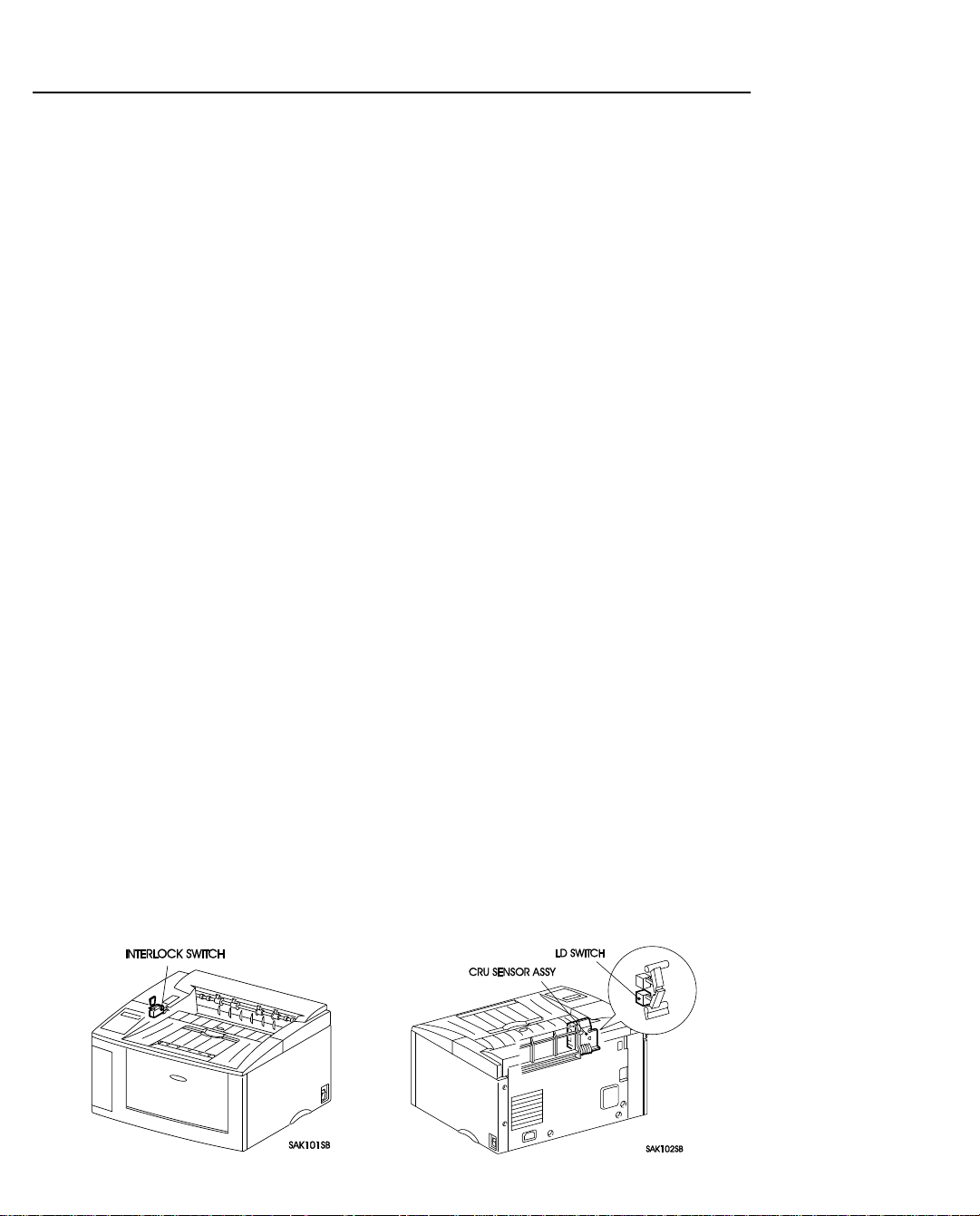
3.2 Laser Beam
To avoid exposure to the laser beam, this printer is equipped with the two safety switches; Interlock
Switch and CRU Switch in the CR U Sensor Assembly. The Interlock Switch turns OFF when opening covers and stops supply of the power. The CRU Switch cuts the circuit when the EP Cartridge is
removed and stops power supply to the circuit of the output of the laser beam.
Caution : 1. Direct eye exposure to the laser beam may cause eye injury or blindness.
2. Never open the covers in which a warning label on the laser beam is sealed.
3. Switch OFF the printer power when you perform removal and reinstallation of the
printer.
4. Be sure to follow the procedure described in this manual when you work on the
printer during its operation.
5. Remove the EP Cartridge before you press the Interlock Switch by hand or tools during maintenance operation. (Do not turn on the Interlock Switch and CRU Switch at
the same time.)
6. Recognize the character of the laser beam and the dangers that are involved that can
inflict harm to the human body, and take precaution when handling the laser beam in
order to avoid injury to you and those around you.
Note : The laser beam is characterized by a very small range of wave lengths and the similar
phase of waves, in contrast with other light (the light of the sun and that of an electric lamp,
for example). Therefore, the laser beam is monochromatic and has a high focusability, and
can reach long distance in a thin beam. The thin laser beam has a very high energy density
and high temperature and can inflict injury to the human body.
Memo : The laser beam used for this printer is invisible and you cannot see it.
Page 8
Introduction — LaserWriter 10/600 A3+ 1 – 5
3.3 Power
When working on the printer, be sure to switch off the printer power and unplug the power cord to
avoid electric shock, burn or injury.
When it is necessary to work with the power on such as when measuring the voltage, conduct the
work with great care to avoid an electric shock and follow the procedures described in this manual.
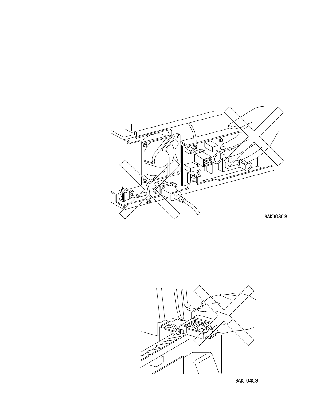
Warning : Do not touch live parts other than those necessary to do so when working on the
printer when power on.
The power switch/inlet section (LVPS Assembly) is supplied with power even if
the power is switched OFF, therefore never touch the live parts.
3.4 Driving Sections
When working on the driving sections such as gears, to avoid injury, make sure to switch the power
OFF, disconnect the power cord, and rotate gears by hand (hand crank).
Warning : Never touch the gears while the printer is in operation.
Page 9
Introduction — LaserWriter 10/600 A3+ 1 – 6
3.5 High Temperature Sections
When working on the high temperature sections such as fuser component, to avoid burn or injury,
make sure to switch the power OFF, disconnect the power cord, and begin to work after the temperature of the component has gone down significantly.
Caution : The temperature is high just after the printer operates, therefore begin to work after let-
ting the component cool down.
3.6 Warning / Caution Labels
Warning and caution labels are sealed on dangerous parts in the printer to warn and prevent accident.
Check whether these labels are firmly sealed in place and are not soiled when performing maintenance or repair.
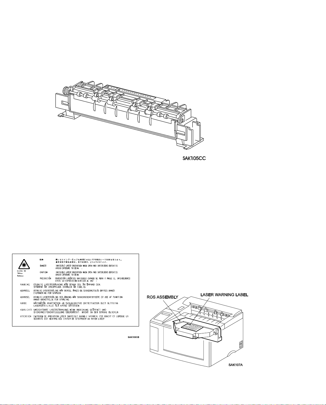
3.6.1 Laser Warning Label
To avoid direct exposure of the laser beam to the engineer, a laser warning label is sealed on top of
the laser output unit (ROS Assembly).
Page 10
Introduction — LaserWriter 10/600 A3+ 1 – 7
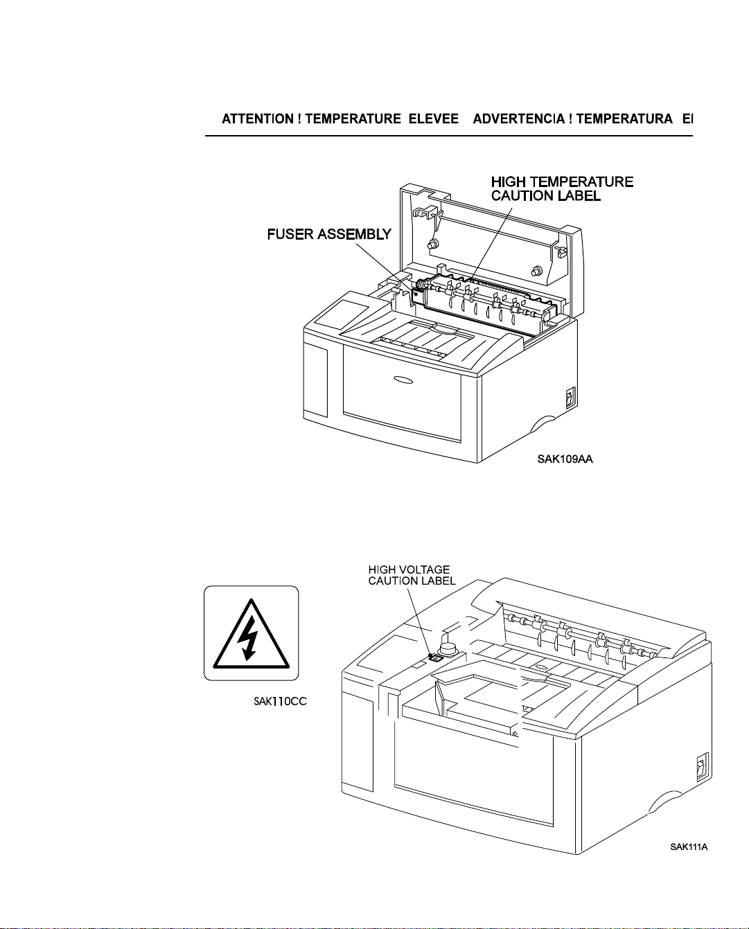
3.6.2 High Temperature Caution Label
To avoid burn of customers, caution labels are sealed on top of the fuser unit (Fuser Assembly).
3.6.3 High Voltage Caution Label
To reduce the risk of electric shocks to the engineer, caution labels are sealed on top of the frame
(Main Frame Assembly) which is on top of the high voltage power supply (HVPS)
.
Page 11

LaserWriter 10/600 A3+
Section 2
Specifications
Section Contents
1. Specifications
1.1 Configuration . . . . . . . . . . . . . . . . . . . . . . . . . . . . . . . . . . . . . .2-1
1.1.1 Basic Configuration. . . . . . . . . . . . . . . . . . . . . . . . . . . . . . . .2-1
1.1.2 Functional Configuration . . . . . . . . . . . . . . . . . . . . . . . . . . . . .2-1
1.2 Functional Specifications. . . . . . . . . . . . . . . . . . . . . . . . . . . . . . . . .2-2
1.2.1 Method of Printing . . . . . . . . . . . . . . . . . . . . . . . . . . . . . . . .2-2
1.2.2 Method of Exposing . . . . . . . . . . . . . . . . . . . . . . . . . . . . . . .2-2
1.2.3 Method of Fusing . . . . . . . . . . . . . . . . . . . . . . . . . . . . . . . . .2-2
1.2.4 Continuous Printing Speed . . . . . . . . . . . . . . . . . . . . . . . . . . . .2-2
1.2.5 Resolution. . . . . . . . . . . . . . . . . . . . . . . . . . . . . . . . . . . . .2-2
1.2.6 Warm-up Time . . . . . . . . . . . . . . . . . . . . . . . . . . . . . . . . . .2-3
1.2.7 Maximum Paper Size . . . . . . . . . . . . . . . . . . . . . . . . . . . . . . .2-3
1.2.8 Maximum Printing Area . . . . . . . . . . . . . . . . . . . . . . . . . . . . .2-3
1.2.9 Maximum Paper held in Output Tray. . . . . . . . . . . . . . . . . . . . . . .2-3
1.2.10 Means for Feeding Paper . . . . . . . . . . . . . . . . . . . . . . . . . . . .2-3
1.2.11 Maximum Sheets of Feeding Paper . . . . . . . . . . . . . . . . . . . . . . .2-3
1.2.12 Paper Weight Limitations . . . . . . . . . . . . . . . . . . . . . . . . . . . .2-4
1.2.13 Types of Paper . . . . . . . . . . . . . . . . . . . . . . . . . . . . . . . . . .2-4
1.2.14 Standard Paper . . . . . . . . . . . . . . . . . . . . . . . . . . . . . . . . .2-4
1.2.15 Paper Size . . . . . . . . . . . . . . . . . . . . . . . . . . . . . . . . . . .2-4
1.3 Electric Specifications . . . . . . . . . . . . . . . . . . . . . . . . . . . . . . . . . .2-6
1.3.1 Power Source . . . . . . . . . . . . . . . . . . . . . . . . . . . . . . . . . . .2-6
1.3.2 Power Consumption . . . . . . . . . . . . . . . . . . . . . . . . . . . . . . .2-6
1.4 Mechanical Specifications . . . . . . . . . . . . . . . . . . . . . . . . . . . . . . . .2-6
1.4.1 Dimensions and Weight. . . . . . . . . . . . . . . . . . . . . . . . . . . . . .2-6
1.4.2 Space Requirements (Minimum Installation Space) . . . . . . . . . . . . . . .2-6
1.5 Operating Environment. . . . . . . . . . . . . . . . . . . . . . . . . . . . . . . . . .2-7
1.5.1 Temperature & Humidity . . . . . . . . . . . . . . . . . . . . . . . . . . . . .2-7
1.5.2 Altitude . . . . . . . . . . . . . . . . . . . . . . . . . . . . . . . . . . . . . .2-7
1.5.3 Horizontal Bias . . . . . . . . . . . . . . . . . . . . . . . . . . . . . . . . . .2-7
1.5.4 Noise(when the front tray is closed) . . . . . . . . . . . . . . . . . . . . . . .2-7
1.6 Printing Accuracy. . . . . . . . . . . . . . . . . . . . . . . . . . . . . . . . . . . . .2-7
Page 12

LaserWriter 10/600 A3+
Section 2
Specifications
2. Consumable
. . . . . . . . . . . . . . . . . . . . . . . . . . . . . . . . . . . . . . . 2-8
3. Parts which require Periodical Replacement
. . . . . . . . . . . . . . 2-8
Page 13
Specifications — LaserWriter 10/600 A3+ 2 – 1
1. Specifications
1.1 Configuration
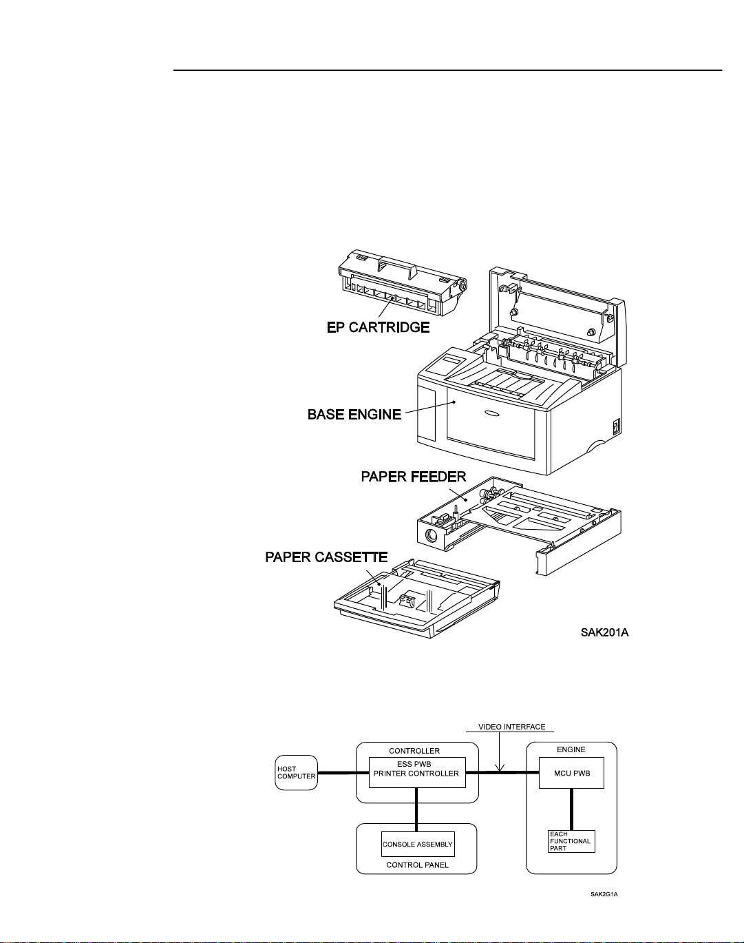
1.1.1 Basic Configuration
The LaserWriter 10/600 A3+ laser printer has two types of configurations;
• Basic configuration 1 = Base engine + EP cartridge
• Basic configuration 2 = Base engine + EP cartridge + Paper feeder + Paper cassette
Note: The basic configuration 2 includes options.
1.1.2 Functional Configuration
Functional configuration of this printer consists of the engine, controller, and control panel.
Page 14

Specifications — LaserWriter 10/600 A3+ 2 – 2
1.2 Functional Specifications
1.2.1 Method of Printing
Electrophotographic printing
1.2.2 Method of Exposing
Scanning done by light beam of a semiconductor laser
1.2.3 Method of Fusing
Fusing by heat and pressure
1.2.4 Continuous Printing Speed
The speed of printing varies depending on the size of paper.
• LETTER(LEF), A4(LEF), EXECUTIVE(LEF), B5(LEF), A5(LEF),
STATEMENT(LEF), Postcard(SEF), MONARCH(SEF) .......................................10.3PPM
• A4(SEF), LETTER(SEF), B5(SEF), C5(SEF), COM-10(SEF), DL(SEF)...............8.1PPM
• B4(SEF), LEGAL14"(SEF), LEGAL13"(SEF)........................................................6.8PPM
• LEDGER(SEF), A3(SEF)..........................................................................................5.9PPM
• Nonstandard size
The speed of printing determined by the specification of the nonstandard size paper is as follows :
Nonstandard size 1 : 5.2PPM
Nonstandard size 2 : 3.0PPM
Note : 1. The specification for nonstandard size is determined by the OEM contract with Fuji
Xerox.
The nonstandard size 1 is standard specification, and the nonstandard size 2 is a special optional specification which is usually not available.
2. SEF is the abbreviation for Short Edge Feed which means feeding of paper with the
short edge (side) facing the front, and LEF for Long Edge Feed which means feeding of
paper with the long edge (side) facing the front.
When neither SEF nor LEF is indicated, the orientation of paper is SEF.
Memo : PPM stands for Prints Per Minute, that is, the number of paper sheets the printer can
print per minute.
1.2.5 Resolution
• 600 dpi (23.62 dot/mm)
Memo : "dpi" is the abbreviation of dots per inch, that is, the number of dots per inch.
Page 15

Specifications — LaserWriter 10/600 A3+ 2 – 3
1.2.6 Warm-up T ime
The warm-up time consists of the time from when the printer power is turned on to when the printer
is ready to print.
Within 65 seconds when the nominal voltage is applied.
Memo : The Main Motor will start to rotate when the warm-up begins and will stop when the
warm-up is completed.
1.2.7 Maximum Paper Size
• For standard paper, maximum printable paper size is either LEDGER or A3.
• For nonstandard size paper, maximum printable paper size is selected by the specification as
follows (provided that only printing operation is possible);
Nonstandard size 1 : Max. 297.0mm x 508.0 mm
Nonstandard size 2 : Max 297.0mm x 900.00mm
Note : The specification for nonstandard size is determined by the OEM contract with Fuji
Xerox. The nonstandard size 1 is standard specification, and the nonstandard size 2 is
special optional specification which is usually not available.
1.2.8 Maximum Printing Area
4.0 millimeters in from all four sides of the standard paper.
1.2.9 Maximum Paper held in Output Tray
250 sheets of A4 Fuji Xerox standard paper type L at the ambient temperature of 22 oC and humidity of 55%RH.
1.2.10 Means for Feeding Paper
This printer has two types of paper feeds :
• Front tray feeding
Multi-sheet manual feeding from the front tray at the front of the printer.
• Cassette feed (optional)
Feeding from paper cassette installed on the paper feeder.
Note : Maximum of two cassettes can be installed on the paper feeder. Feeding is available with
maximum of three cassettes or trays.
1.2.11 Maximum Sheets of Feeding Paper
• Front tray feeding
Standard paper = 150 sheets, Postcard=75 sheets, Specified envelope=20 sheets
Specified label = 75 sheets, Specified OHP film(transparencies)=75 sheets
• Cassette feeding
Page 16

Specifications — LaserWriter 10/600 A3+ 2 – 4
- Universal Cassette
Standard paper = 250 sheets,Specified label = 20 sheets,
Specified OHP film (transparencies)=20 sheets
1.2.12 Paper Weight Limitations
• Front tray feeding
Normal paper60~135g/m
Postcards190g/m
2
2
• Cassette feeding
Normal paper60~90g/m
2
1.2.13 Types of Paper
Standard paper (cut sheets), postcards, specified envelopes, specified labels and specified OHP
films(transparencies)
1.2.14 Standard Paper
Fuji Xerox L paper (size A4 and A3), XEROX 4024DP (Letter)
1.2.15 Paper Size
Available paper size is selected by the specification of standard paper and the nonstandard paper.
Specifications for standard size :
For front tray feeding, all specified paper sizes are available. Cassette feed can be used for up
to eight types of paper.
• Front tray feeding (19 types of standard size + nonstandard size)
LEDGER(SEF), A3(SEF), B4(SEF), LEGAL14"(SEF), LEGAL13"(SEF), A4(SEF),
LETTER(SEF), LETTER(LEF), A4(LEF), B5(SEF), EXECUTIVE(LEF), B5(LEF),
A5(LEF), STATEMENT(LEF)
Postcard (SEF), C5(SEF), COM-10(SEF), DL(SEF), MONARCH(SEF)
Nonstandard size(See the "Specification for nonstandard size")
• Cassette feeding
- Universal Cassette (8 types)
A3(SEF), B4(SEF), LEGAL14"(SEF), A4(SEF), LETTER(LEF), A4(LEF),
B5(LEF), A5(LEF)
Memo : The dimensions for each paper type are shown below ; (unit : mm)
Standard paper : LEDGER [279.4 x 431.8], A3[297.0 x 420.0],
B4 [257.0 x 364.0],LEGAL14"[215.9 x 355.6],
LEGAL13"[215.9 x 330.2]
A4[210.0 x 297.0], LETTER[215.9 x 279.4]
EXECUTIVE [184.2 x 266.7], B5 [182.0 x 257.0]
A5[149.0 x 210.0], STATEMENT[139.7 x 215.9]
Page 17

Specifications — LaserWriter 10/600 A3+ 2 – 5
Postcard : Postal card [100.0 x 148.0]
Specifications for nonstandard size :
There are two specifications according to the combination of the nonstandard size 1 and 2, that
is, "only nonstandard size 1" and "nonstandard size 1 and 2". The paper size for nonstandard is
determined by the specifications.
• Nonstandard size 1 : Laser beam scanning direction : 86mm~305mm,
Paper feed direction : 90mm~508mm
• Nonstandard size 2 : Laser beam scanning direction : 86mm~305mm,
Paper feed direction : 90mm~900mm
Note : 1. The specification for nonstandard size is determined by the OEM contract with Fuji
Xerox. The nonstandar d size 1 is standard specification, and the nonstandard size 2 is a
special optional specification which is usually not available.
2. This printer can print on nonstandard size paper, while the print quality and the reliability of feeding are out of the scope of the specification.
Page 18
Specifications — LaserWriter 10/600 A3+ 2 – 6
1.3 Electric Specifications
1.3.1 Power Source
Power supply specifications are listed below:
• 220V mode
Voltage : 220/240VAC (198~264VAC), Frequency : 50/60 Hz (47~63Hz)
1.3.2 Power Consumption
The maximum power consumption of the LaserWriter 10/600 A3+ laser printer (not including the
Printer Controller and associated components) during printing and during the Sleep Mode (stops
the power supply to the fuser) are as follows;
• Operating voltage 100VAC : Printing................... 550 watts or less
Sleep mode.............15watts or less
• Operating voltage 120VAC: Printing...................650 watts or less
Sleep mode.............5 watts or less
• Operating voltage 240VAC: Printing...................TBD watts or less
Sleep mode.............TBD watts or less
1.4 Mechanical Specifications
1.4.1 Dimensions and Weight
EP cartridge, Printer Controller, and their attached parts are not included.
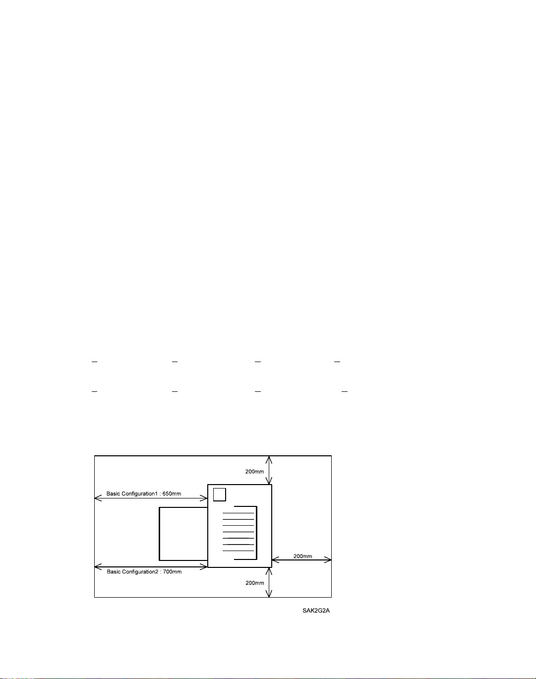
• For Basic configuration 1(Only front tray feeding)
Width : 466 +
• For Basic configuration 2 (with the 1st cassette feeding)
Width : 466 + 5mm,Depth : 497 + 5mm,Height : 324 + 5mm,Weight : 18.5 + 1Kg
1.4.2 Space Requirements (Minimum Installation Space)
400mm minimum overhead clearance
.
5mm,Depth : 386 + 5mm,Height : 257 + 5mm,Weight : 14 + 1Kg
Page 19

Specifications — LaserWriter 10/600 A3+ 2 – 7
1.5 Operating Environment
1.5.1 Temperature & Humidity
5 ~ 35oC / 15 ~ 85%RH (with no dew condensation)
1.5.2 Altitude
0 ~ 2500m
1.5.3 Horizontal Bias
Less than 5oC off level
1.5.4 Noise (when the front tray is closed)
• Machine running : 49.8 dB
• Machine in standby : 32.0 dB
1.6 Printing Accuracy
Memo : For more information, read "How to read Printing Accuracy" in Section 6 of this man-
ual.
• Lead Edge Registration : +
• Side Edge Registration : + 2.5mm or less
•Skew :+ 2.0mm or less (at a width of 245mm)
• Vertical Accuracy : + 1.3mm or less (at a width of 210mm)
• Horizontal Accuracy : + 2.0mm or less
• Linearity in the direction
of paper trave : + 1.0mm or less (at a width of 390mm)
• Magnification accuracy in
the direction of paper trave : 100 + 0.8% or less (at a width of 390mm)
2.0mm or less
(at a width of 245mm and a height of height of 390mm)
Page 20

Specifications — LaserWriter 10/600 A3+ 2 – 8
2. Consumable
Usually customers can replace consumable.
When a consumable causes a trouble, or when trouble is resolved by the replacement of a consum-
able, customer engineer may replace it.
• Paper
See paper specification mentioned in this section.
• EP cartridge
EP cartridge is an integrated unit which includes photoreceptor, black toner, charger, developer, and cleaner.
Note : EP cartridge has an average life of 6000 prints (A4 size (LEF) with 5% image coverage).
The life varies depending on the sensitivity of the photoreceptor and the contents of the
image.
3.Parts which require Periodical Replacement
To avoid trouble, the following units are recommended to be replaced when the printer reaches a
specified number of prints.
• Fuser Assembly : Life=100000 prints
• Pick Up Roll : Life=100000 prints
• Retard Pad Assembly : Life=100000 prints
Note : The life is the number of the prints on standard paper of A4(LEF). Life may decrease by
half when printing on nonstandard size paper or A3 paper.
Memo : The following rollers and parts are considered to wear off with paper;
BTR Assembly, Trans. Chute Assembly, Feed Roll, Turn Roll Assembly
( Standard paper of A4(LEF)
( Standard paper of A4(LEF)
( Standard paper of A4(LEF)
)
)
)
Page 21

LaserWriter 10/600 A3+
Section Contents
1. Parts Lists
Section 3
Parts Lists
1.1 Notes on using Parts Lists
PL1 Covers . . . . . . . . . . . . . . . . . . . . . . . . . . . . . . . . . . . . . . . . 3-2
PL2 Fuser & Paper Exit . . . . . . . . . . . . . . . . . . . . . . . . . . . . . . . . . 3-4
PL3 Paper Transportation . . . . . . . . . . . . . . . . . . . . . . . . . . . . . . . . 3-6
PL4 Multi Sheet Inserter . . . . . . . . . . . . . . . . . . . . . . . . . . . . . . . . . 3-8
PL5 Drive & Xerographic . . . . . . . . . . . . . . . . . . . . . . . . . . . . . . . 3-10
PL6 Electrical . . . . . . . . . . . . . . . . . . . . . . . . . . . . . . . . . . . . . 3-12
PL7 250 Feeder. . . . . . . . . . . . . . . . . . . . . . . . . . . . . . . . . . . . . 3-14
PL9 250 Cassette . . . . . . . . . . . . . . . . . . . . . . . . . . . . . . . . . . . . 3-16
2. Parts Reference
. . . . . . . . . . . . . . . . . . . . . . . . . . . . . . . . . . . 3-18
. . . . . . . . . . . . . . . . . . . . . . . . . . . 3-1
Page 22

LaserWriter 10/600 A3+ 3 – 1
1. Parts Lists
This printer is divided into 10 plates(PL) as shown below according to the specification.
This section provides illustrations for assembly and corresponding part names.
• PL1 Cover • PL6 Electrical
• PL2 Fuser & Paper Exit • PL7 250 Feeder
• PL3 Paper Transportation
• PL4 Multi Sheet Inserter • PL9 250 Cassette
• PL5 Drive & Xerographics
1.1 Notes on using Parts Lists
1. The numbers in illustration correspond to item numbers in the list to find the names of parts.
2. "PLX.Y" indicates that the part is shown as item Y in plate X.
3. The alphabet characters in the illustration represents types of screws or clips ,etc. as follows:
E=Ering, S=Screw ,N=Hexagonal nutt,K=KL clip.
4. The mark t represents the items of assembly parts in the illustration.
5. A circled alphabet character with a line in the illustration indicates the cut of the line at that
point. It is connected to the point of the same alphabet character.
6. "With(2-5)",which is labeled on the assembly part in illustration or list, indicates it includes
item 2,3,4,and 5 of the specific plate. "With(2-5),PL6.7"means it includes item 2,3,4,and 5
of the specific plate and item 7 of the plate 6.
7. Items with $ are recommended parts(recommended spare parts)which principally can be
supplied.(Other items need to be discussed to supply.)
8. Parts with * in the list have "note" or "memo" for reference described on the same page.
9. "
(J1-J2,P3)
ness or wire is the J1 of the connector and another terminal is jack 2 and plug 3 of the connector.
(For the location of connector (P/J),see"Section6.4.Connector Locations.")
10. "High Assembly" in the list indicates upper assembly parts which include the specific parts.
"which is labeled on the harness or wire, etc., indicates one terminal of the har-
Note : 1. For information on spare parts, see "Spare parts lists" issued separately.
2. According to the specification of OEM, configuration may differ and some parts may not
exist.(Especially for "PL5 Electrical", major difference may exist according to the specification.)
Page 23
Parts Lists — LaserWriter 10/600 A3+ 3 – 2
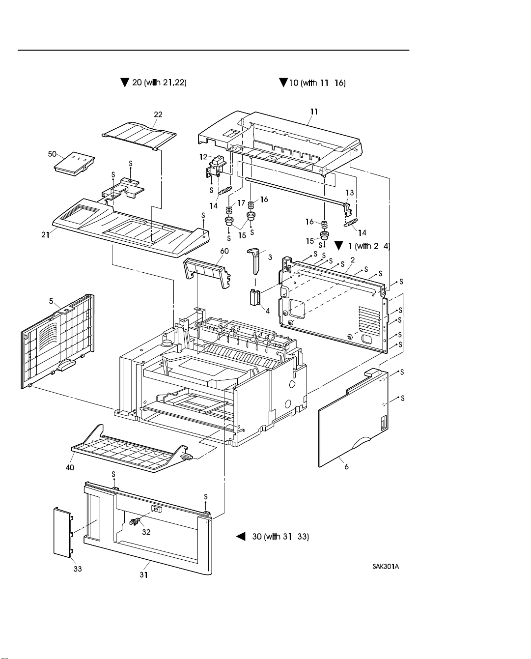
PL1 Covers
Page 24

Parts Lists — LaserWriter 10/600 A3+ 3 – 3
PL1 Covers
Item Parts Name High Assembly
1 REAR FRAME ASSEMBLY (with2-4) ..........................................----
2 REAR FRAME................................................................................. PL1.1
3 PUSH LEVER..................................................................................PL1.1
4 LEVER HOLDER............................................................................PL1.1
5 LEFT COVER..................................................................................----
6 RIGHT COVER ...............................................................................----
10 POP UP ASSEMBLY (with11-17) ..................................................----
11 POP UP COVER.............................................................................. PL1.10
12 LATCH BUTTON............................................................................PL1.10
13 LATCH ASSEMBLY.......................................................................PL1.10
14 LATCH SPRING..............................................................................PL1.10
15 CRU STOPPER................................................................................PL1.10
16 STOPPER SPRING..........................................................................PL1.10
17 POP UP SPRING..............................................................................PL1.10
20 TOP COVER ASSEMBLY (with21,22) .........................................----
21 TOP COVER....................................................................................PL1.20
22 TOP TRAY....................................................................................... PL1.20
30 FRONT COVER ASSEMBLY (with31-33)....................................----
31 FRONT COVER...............................................................................PL1.30
32 TRAY LATCH.................................................................................PL1.30
33 GUIDE COVER............................................................................... PL1.30
40 FRONT TRAY ................................................................................ ----
$
50 CONSOLE ASSEMBLY .................................................................----
Page 25
Parts Lists — LaserWriter 10/600 A3+ 3 – 4
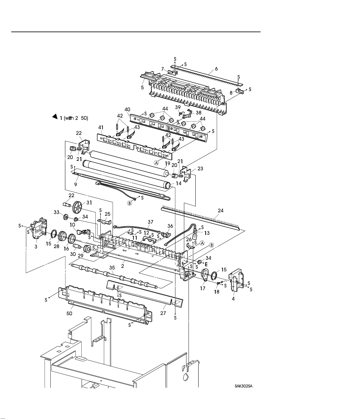
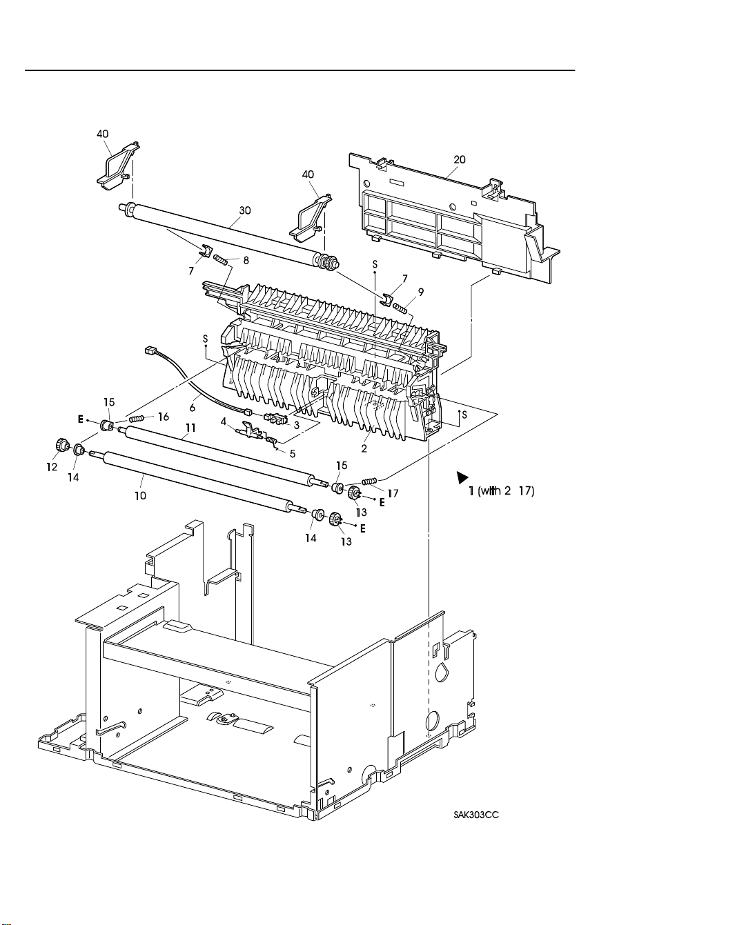
PL2 Fuser & Paper Exit
Page 26

Parts Lists — LaserWriter 10/600 A3+ 3 – 5
PL2 Fuser & Paper Exit
Item Parts Name High Assembly
1 FUSER ASSEMBLY (with2-50)*1.................................................----
2 FUSER FRAME ASSEMBLY.........................................................PL2.1
3 FUSER COVER L............................................................................ PL2.1
4 FUSER COVER R............................................................................PL2.1
5 FUSER TOP COVER ASSEMBLY ................................................PL2.1
6 EXIT ELIMINATOR....................................................................... PL2.1
7 ELIMINATOR BRACKET L.......................................................... PL2.1
8 ELIMINATOR BRACKET R..........................................................PL2.1
9 HEATER ROD.................................................................................PL2.1
10 LAMP GUIDE..................................................................................PL2.1
11 THERMAL FUSE............................................................................PL2.1
12 THERMOSTAT ...............................................................................PL2.1
13 TEMPERATURE SENSOR ASSEMBLY ......................................PL2.1
14 HEAT ROLL....................................................................................PL2.1
15 H/R RING......................................................................................... PL2.1
16 H/R BEARING L .............................................................................PL2.1
17 H/R BEARING R.............................................................................PL2.1
18 H/R DIODE......................................................................................PL2.1
19 PRESSURE ROLL...........................................................................PL2.1
20 P/R BEARING .................................................................................PL2.1
21 NIP SPRING.....................................................................................PL2.1
22 NIP LEVER L ..................................................................................PL2.1
23 NIP LEVER R.................................................................................. PL2.1
24 P/R ELIMINATOR ..........................................................................PL2.1
25 P/R EARTH PLATE L.....................................................................PL2.1
26 P/R EARTH PLATE R..................................................................... PL2.1
27 FUSER INLET CHUTE...................................................................PL2.1
28 H/R GEAR........................................................................................PL2.1
29 H/R IDLER GEAR...........................................................................PL2.1
30 H/R IDLER SHAFT.........................................................................PL2.1
31 EXIT IDLER GEAR ........................................................................PL2.1
32 EXIT IDLER SHAHT......................................................................PL2.1
33 EXIT GEAR..................................................................................... PL2.1
34 EXIT BEARING ..............................................................................PL2.1
35 EXIT ROLL ASSEMBLY ...............................................................PL2.1
36 EXIT SENSOR................................................................................. PL2.1
37 EXIT HARNESS (J152-J153).......................................................... PL2.1
38 EXIT ACTUATOR ..........................................................................PL2.1
39 EXIT TORSION SPRING................................................................PL2.1
40 EXIT CHUTE................................................................................... PL2.1
41 FINGER BRACKET........................................................................PL2.1
42 FINGER SPRING.............................................................................PL2.1
43 H/R FINGER....................................................................................PL2.1
44 EXIT CHUTE ROLL .......................................................................PL2.1
50 EXIT COVER...................................................................................PL2.1
*1
: Periodic Replacement Parts
Page 27
Parts Lists — LaserWriter 10/600 A3+ 3 – 6
PL3 Paper Transportation
Page 28

Parts Lists — LaserWriter 10/600 A3+ 3 – 7
PL3 Paper Transportation
Item Parts Name High Assembly
$
1 TRANSPORT CHUTE ASSEMBLY (with2-17)............................----
2 TRANSPORT SUB ASSEMBLY.................................................... PL3.1
3 REGISTRATION SENSOR............................................................. PL3.1
4 REGISTRATION ACTUATOR ......................................................PL3.1
5 REGISTRATION SPRING..............................................................PL3.1
6 REGISTRATION SENSOR HARNESS (P122-J123)..................... PL3.1
7 BTR BEARING................................................................................PL3.1
8 BTR SPRING L................................................................................ PL3.1
9 BTR SPRING R................................................................................PL3.1
10 RUBBER REGISTRATION ROLL.................................................PL3.1
11 METAL REGISTRATION ROLL...................................................PL3.1
12 REGISTRATION IN GEAR............................................................PL3.1
13 REGISTRATION OUT GEAR........................................................PL3.1
14 REGISTRATION FRONT BEARING............................................ PL3.1
15 REGISTRATION BACK BEARING.............................................. PL3.1
16 REGISTRATION ROLL SPRING L...............................................PL3.1
17 REGISTRATION ROLL SPRING R............................................... PL3.1
20 CHUTE PLATE ...............................................................................----
$
30 BTR ASSEMBLY ...........................................................................----
40 BTR STOPPER *1 .......................................................................... ----
*1
: This keeps the BTR ASSEMBLY attached with the Transport Sub Assembly during transporta-
tion. Remove it during installation.
Page 29
Parts Lists — LaserWriter 10/600 A3+ 3 – 8
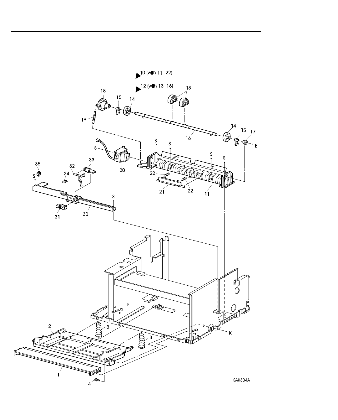
PL4 Multi Sheet Inserter
Page 30

Parts Lists — LaserWriter 10/600 A3+ 3 – 9
PL4 Multi Sheet Inserter
Item Parts Name High Assembly
1 FRONT IN TRAY............................................................................----
2 FRONT BOTTOM TRAY ...............................................................----
3 MSI N/F SPRING.............................................................................----
4 BOTTOM TRAY STUD..................................................................----
$
10 MSI CHUTE ASSEMBLY (with11-22) ..........................................----
11 MSI CHUTE..................................................................................... PL4.10
12 PICK UP ROLL ASSEMBLY (with13-16).....................................PL4.10
$
13 PICK UP ROLL *1...........................................................................PL4.12
14 CORE ROLL....................................................................................PL4.12
15 PICK UP CAM.................................................................................PL4.12
16 PICK UP SHAFT .............................................................................PL4.12
17 TRANSPORT BEARING................................................................PL4.10
18 PICK UP GEAR...............................................................................PL4.10
19 PICK UP SPRING............................................................................ PL4.10
20 PICK UP SOLENOID......................................................................PL4.10
$
21 RETARD PAD ASSEMBLY *1......................................................PL4.10
22 RETARD SPRING...........................................................................PL4.10
30 SENSOR BRACKET....................................................................... ----
$
31 MSI NO PAPER SENSOR...............................................................----
32 MSI N/P ACTUATOR.....................................................................----
33 CLAMP S......................................................................................... ----
35 CLAMP M........................................................................................----
*1
: Periodic Replacement Parts
Page 31

Parts Lists — LaserWriter 10/600 A3+ 3 – 10
PL5 Drive & Xerographics
Page 32

Parts Lists — LaserWriter 10/600 A3+ 3 – 11
PL5 Drive & Xerographics
Item Parts Name High Assembly
1 MAIN FRAME ASSEMBLY ..........................................................----
2 CLAMP P......................................................................................... ----
3 FRAME BRACKET......................................................................... ----
$
10 ROS ASSEMBLY (with11-13)........................................................----
11 ROS SUB ASSEMBLY ...................................................................PL5.10
12 SCANNER ASSEMBLY................................................................. PL5.10
13 SOS HARNESS (J111-J113)............................................................PL5.10
$
20 DRIVE ASSEMBLY........................................................................----
$
21 REGISTRATION CLUTCH ASSEMBLY...................................... ----
22 REGISTRATION DRIVE GEAR....................................................----
23 DRIVE BEARING L........................................................................ ----
24 DRIVE BEARING R........................................................................----
$
30 CRU SENSOR ASSEMBLY ...........................................................----
31 CRU GUIDE ASSEMBLY L........................................................... ----
32 CRU GUIDE ASSEMBLY R...........................................................----
40 BASE PLATE *1..............................................................................----
41 EP CARTRIDGE *2.........................................................................----
*1
: This is only for basic configuration 1. This part is removed when Feeder 250 is installed for
use.
*2
: Consumable
Page 33

Parts Lists — LaserWriter 10/600 A3+ 3 – 12
PL6 Electrical
Page 34

Parts Lists — LaserWriter 10/600 A3+ 3 – 13
PL6 Electrical
Item Parts Name High Assembly
$
1 LVPS ASSEMBLY..........................................................................----
$
2 HVPS................................................................................................----
3 KNOB VOLUME............................................................................. ----
$
4 MCU PWB .......................................................................................----
$
5 FAN.................................................................................................. ----
$
6 INTERLOCK SWITCH................................................................... ----
10 LVPS HARNESS (J10-J101)...........................................................----
11 HVPS HARNESS (J13-J131)...........................................................----
12 ROS HARNESS (J11-J112,J114).....................................................----
13 FUSER HARNESS (J15-J151,J154)................................................----
14 P/H HARNESS (J12-J121,J122,J124,P125) ....................................----
15 CRU HARNESS (J16-J161).............................................................----
16 TRAY HARNESS (J17-J171)..........................................................----
17 HARNESS ASSEMBLY LED (J127-J128)..................................... ----
20 BUSH................................................................................................----
21 EDGE SADDLE............................................................................... ----
22 CLAMP L.........................................................................................----
23 CONNECTOR 2PW......................................................................... ----
24 CONNECTOR 3PB..........................................................................----
30 HARNESS SHIELD......................................................................... ----
31 ELECTRIC SHIELD........................................................................----
32 REAR PANEL..................................................................................----
33 SHIELD ASSEMBLY (with34,35)..................................................----
34 CONTROLLER SHIELD.................................................................PL6.33
35 OPTION SHIELD ............................................................................PL6.33
36 ESS HARNESS (J106-J142)............................................................----
37 ESS PWB..........................................................................................----
Page 35

Parts Lists — LaserWriter 10/600 A3+ 3 – 14
PL7 250 Feeder
Page 36

Parts Lists — LaserWriter 10/600 A3+ 3 – 15
PL7 250 Feeder
Item Parts Name High Assembly
1 FEEDER ASSEMBLY 250 (with2-34)............................................----
2 FEEDER FRAME 250 .....................................................................PL7.1
3 FEED ROLL ASSEMBLY (with4,5)...............................................PL7.1
4 FEED SHAFT ASSEMBLY............................................................ PL7.3
$
5 FEED ROLL..................................................................................... PL7.3
$
6 TURN ROLL ASSEMBLY..............................................................PL7.1
7 FEED BEARING .............................................................................PL7.1
8 TRANSPORT BEARING................................................................PL7.1
9 FEED SPRING.................................................................................PL7.1
$
10 FEED SOLENOID........................................................................... PL7.1
11 FEED GEAR ....................................................................................PL7.1
12 FEED IDLER GEAR........................................................................PL7.1
$
13 ELECTRIC CLUTCH .....................................................................PL7.1
15 TURNTURN IDLER GEAR............................................................ PL7.1
16 IN GEAR..........................................................................................PL7.1
17 OUT GEAR......................................................................................PL7.1
18 SIZE GEAR......................................................................................PL7.1
$
19 FEEDER PWB .................................................................................PL7.1
20 PWB BRACKET..............................................................................PL7.1
$
21 CASSETTE SENSOR......................................................................PL7.1
$
22 CST NO PAPER SENSOR ..............................................................PL7.1
23 HARNESS GUIDE...........................................................................PL7.1
24 CASSETTE HARNESS (J175-J271,J272,J273)..............................PL7.1
25 TRAY UPPER HARNESS (P171-J173)..........................................PL7.1
26 TRAY LOWER HARNESS (J174-J171)......................................... PL7.1
27 CONNECTOR BRACKET..............................................................PL7.1
$
28 OUTER CHUTE ASSEMBLY........................................................ PL7.1
29 FEED HOUSING L.......................................................................... PL7.1
30 FEED HOUSING R..........................................................................PL7.1
31 FEEDER EARTH PLATE ...............................................................PL7.1
32 FEEDER TIE PLATE ......................................................................PL7.1
33 HOUSING CAP ...............................................................................PL7.1
34 FEEDER EARTH WIRE..................................................................PL7.1
50 FEEDER JOINT...............................................................................----
Page 37

Parts Lists — LaserWriter 10/600 A3+ 3 – 16
PL9 250 Cassette
Page 38

Parts Lists — LaserWriter 10/600 A3+ 3 – 17
PL9 250 Cassette
Item Parts Name High Assembly
1 UNIVERSAL CASSETTE (with10-21)...........................................PL9.1
10 CASSETTE HOUSING ...................................................................PL9.1
11 BOTTOM PLATE ASSEMBLY......................................................PL9.1
12 CST N/F SPRING ............................................................................PL9.1
13 CST LATCH L.................................................................................PL9.1
14 CST LATCH R.................................................................................PL9.1
15 CST LATCH SPRING .....................................................................PL9.1
16 INNER CHUTE................................................................................PL9.1
17 INNER SPRING............................................................................... PL9.1
18 EXTENSION HOUSING................................................................. PL9.1
19 END GUIDE.....................................................................................PL9.1
20 END GUIDE LOWER .....................................................................PL9.1
21 CASSETTE COVER........................................................................PL9.1
Page 39

Parts Lists — LaserWriter 10/600 A3+ 1 – 18
2. Parts Reference
[A]
ACTUATOR HOLDER.......................PL 4.33
[B]
BASE PLATE............................... ......PL5.40
BOTTOM PLATE ASSEMBLY..........PL 9.11
BOTTOM TRAY STUD .....................PL 4. 4
BTR ASSEMBL Y ...............................PL 3.30
BTR BEARING ..................................PL 3. 7
BTR SPRING L ..................................PL 3. 8
BTR SPRING R ..................................PL 3. 9
BTR STOPPER...................................PL 3.40
BUSH ..................................................PL 6.20
[C]
CASSETTE COVER...........................PL 9.21
CASSETTE HARNESS......................PL 7.24
CASSETTE HOUSING......................PL 9.10
CASSETTE SENSOR.........................PL 7.21
CHUTE PLATE...................................PL 3.20
CLAMP L............................................PL 6.22
CLAMP M...........................................PL 4.35
CLAMP P............................................PL 5. 2
CLAMP S............................................PL 4.34
CONNECTOR 2PW............................PL 6.23
CONNECTOR 3PB.............................PL 6.24
CONNECTOR BRACKET.................PL 7.27
CONSOLE ASSEMBL Y.....................PL 1.50
CONTROLLER SHIELD ...................PL 6.34
CORE ROLL.......................................PL 4.14
CRU GUIDE ASSEMBLY L ..............PL 5.31
CRU GUIDE ASSEMBLY R..............PL 5.32
CRU HARNESS..................................PL 6.15
CRU SENSOR ASSEMBLY...............PL 5.35
CRU STOPPER...................................PL 1.15
CST LATCH L ....................................PL 9.13
CST LATCH R ....................................PL 9.14
CST LATCH SPRING ........................PL 9.15
CST N/F SPRING...............................PL 9.12
CST NO PAPER SENSOR.................PL7.22
[D]
DRIVE ASSEMBL Y...........................PL 5.20
DRIVE BEARING L ..........................PL 5.23
DRIVE BEARING R ..........................PL 5.24
[
E]
EDGE SADDLE .................................PL 6.21
ELECTRIC CLUTCH.........................PL 7.13
ELECTRIC SHIELD...........................PL 6.31
ELIMINATOR BRACKET L..............PL 2. 7
ELIMINATOR BRACKET R..............PL 2. 8
END GUIDE.......................................PL 9.19
END GUIDE LOWER........................ PL 9.20
EP CARTRIDGE................................PL 5.50
ESS HARNESS...................................PL 6.36
ESS PWB............................................PL 6.37
EXIT ACTUATOR.............................. PL 2.38
EXIT BEARING................................. PL 2.34
EXIT CHUTE .....................................PL 2.40
EXIT CHUTE ROLL.......................... PL 2.44
EXIT COVER.....................................PL 2.50
EXIT ELIMINATOR ..........................PL 2. 6
EXIT GEAR........................................PL 2.33
EXIT HARNESS ................................ PL 2.37
EXIT IDLER GEAR...........................PL 2.31
EXIT IDLER SHAFT.........................PL 2.32
EXIT ROLL ASSEMBLY...................PL 2.35
EXIT SENSOR ...................................PL 2.36
EXIT TORSION SPRING..................PL 2.39
EXTENSION HOUSING ...................PL 9.18
[F]
FAN.....................................................PL 6. 5
FEED BEARING................................PL 7. 7
FEED GEAR....................................... PL 7.11
FEED HOUSING L ............................PL 7.29
FEED HOUSING R............................PL 7.30
FEED IDLER GEAR..........................PL 7.12
FEED ROLL .......................................PL 7. 5
FEED ROLL ASSEMBLY..................PL 7. 3
FEED SHAFT ASSEMBLY ............... PL 7. 4
FEED SOLENOID..............................PL 7.10
FEED SPRING....................................PL 7. 9
FEEDER ASSEMBLY 250.................PL 7. 1
FEEDER EARTH PLATE...................PL 7.31
FEEDER EARTH WIRE....................PL 7.34
FEEDER FRAME 250........................ PL 7. 2
FEEDER JOINT..................................PL 7.50
FEEDER PWB....................................PL 7.19
FEEDER TIE PLATE..........................PL 7.32
FINGER BRACKET...........................PL 2.41
FINGER SPRING...............................PL 2.42
FRAME BRACKET ..........................PL 5. 3
FRONT BOTTOM TRAY...................PL 4. 2
FRONT COVER.................................PL 1.31
FRONT COVER ASSEMBLY............PL 1.30
FRONT IN TRAY ...............................PL 4. 1
FRONT TRAY ....................................PL 1.40
FUSER ASSEMBLY...........................PL 2. 1
FUSER COVER L...............................PL 2. 3
FUSER COVER R..............................PL 2. 4
FUSER FRAME ASSEMBLY............ PL 2. 2
FUSER HARNESS.............................PL 6.13
FUSER INLET CHUTE ..................... PL 2.27
FUSER TOP COVER
[G]
GUIDE COVER..................................PL 1.33
[
H]
H/R BEARING L................................ PL 2.16
H/R BEARING R ............................... PL 2.17
H/R DIODE ........................................ PL 2.18
H/R FINGER ...................................... PL 2.43
H/R GEAR..........................................PL 2.28
H/R IDLER GEAR ............................. PL 2.29
H/R IDLER SHAFT ........................... PL 2.30
H/R RING...........................................PL 2.15
HARNESS ASSEMBLY LED............PL 6.17
HARNESS GUIDE.............................PL 7.25
HARNESS SHIELD...........................PL 6.30
HEAT ROLL .......................................PL 2.14
HEATER ROD....................................PL 2. 9
HOUSING CAP.................................. PL 7.33
HVPS .................................................. PL 6. 2
HVPS HARNESS...............................PL 6.11
[I]
IN GEAR ............................................ PL 7.16
INNER CHUTE..................................PL 9.16
INNER SPRING.................................PL 9.17
INTERLOCK SWITCH......................PL 6. 6
[K]
KNOB VOLUME................................PL 6. 3
[L]
LAMP GUIDE....................................PL 2.10
LA TCH ASSEMBLY..........................PL 1.13
LATCH BUTTON............................... PL 1.12
LATCH SPRING ................................ PL 1.14
LEFT COVER.....................................PL 1. 5
LEVER HOLDER .............................. PL 1. 4
LVPS ASSEMBLY.............................PL 6. 1
LVPS HARNESS ................................ PL 6.10
[M]
MAIN FRAME ASSEMBLY .............PL 5. 1
MCU PWB.......................................... PL 6. 4
METAL REGISTRATION ROLL......PL 3.11
MSI CHUTE.......................................PL 4.11
MSI CHUTE ASSEMBLY .................PL 4.10
ASSEMBLY ..... PL 2. 5
Page 40

Parts Lists
MSI N/F SPRING................................PL 4. 3
MSI N/P ACTUATOR........................PL 4.32
MSI NO PAPER SENSOR..................PL 4.31
[N]
NIP LEVER L .....................................PL 2.22
NIP LEVER R.....................................PL 2.23
NIP LEVER SPRING..........................PL 2.21
[O]
OPTION SHIELD ...............................PL 6.35
OUT GEAR.........................................PL 7.17
OUTER CHUTE ASSEMBLY............PL 7.28
[P]
P/H HARNESS....................................PL 6.14
P/R BEARING ....................................PL 2.20
P/R EARTH PLATE L.........................PL 2.25
P/R EARTH PLATE R ........................PL 2.26
P/R ELIMINATOR..............................PL 2.24
PICK UP CAM....................................PL 4.15
PICK UP GEAR..................................PL 4.18
PICK UP ROLL...................................PL 4.13
PICK UP ROLL ASSEMBLY.............PL 4.12
PICK UP SHAFT ................................PL 4.16
PICK UP SOLENOID.........................PL 4.20
PICK UP SPRING...............................PL 4.19
POP UP ASSEMBLY..........................PL 1.10
POP UP COVER.................................PL 1.11
POP UP SPRING.................................PL 1.17
PRESSURE ROLL..............................PL 2.19
PUSH LEVER.....................................PL 1. 3
PWB BRACKET.................................PL 7.20
[R]
REAR FRAME....................................PL 1. 2
REAR FRAME ASSEMBLY..............PL 1. 1
REAR PANEL.....................................PL 6.32
REGISTRATION ACTUATOR...........PL 3. 4
REGISTRATION BACK
BEARING......PL 3.15
REGISTRATION
CLUTCH ASSEMBL Y......PL 5.21
REGISTRATION DRIVE GEAR .......PL 5.22
REGISTRATION
FRONT BEARING......PL 3.14
REGISTRATION IN GEAR ...............PL 3.12
REGISTRATION OUTGEAR ............PL 3.13
REGISTRATION
ROLL SPRING L......PL 3.16
REGISTRATION ROLL
SPRING R......PL 3.17
REGISTRATION SENSOR ................PL 3. 3
REGISTRATION SENSOR
HARNESS......PL 3. 6
REGISTRATION SPRING .................PL 3. 5
RETARD PAD ASSEMBLY...............PL 4.21
RETARD SPRING..............................PL 4.22
RIGHT COVER ..................................PL 1. 6
ROS ASSEMBL Y................................PL 5.10
ROS HARNESS..................................PL 6.12
ROS SUB ASSEMBLY.......................PL 5.11
RUBBER REGISTRATION
ROLL......PL 3.10
[S]
SCANNER ASSEMBL Y ....................PL 5.12
SENSOR BRACKET..........................PL 4.30
SHIELD ASSEMBL Y.........................PL 6.33
SIZE HANDLE...................................PL 7.18
SOS HARNESS ..................................PL 5.13
STOPPER SPRING.............................PL 1.16
[T]
TEMPERATURE
SENSOR ASSEMBL Y.....PL 2.13
THERMAL FUSE...............................PL 2.11
THERMOSTAT...................................PL 2.12
TOP COVER.......................................PL 1.21
TOP COVER ASSEMBLY.................PL 1.20
TOP TRAY ..........................................PL 1.22
TRANSPORT BEARING...................PL 4.17
TRANSPORT BEARING...................PL 7. 8
TRANSPORT CHUTE
ASSEMBLY .....PL 3. 1
TRANSPORT SUB ASSEMBLY.......PL 3. 2
TRAY HARNESS ...............................PL 6.16
TRAY LATCH.....................................PL 1.32
TRAY LOWER HARNESS ................PL 7.26
TURN IDLER GEAR .........................PL 7.15
TURN ROLL ASSEMBLY.................PL 7. 6
[U]
UNIVERSAL CASSETTE .................PL 9. 1
Page 41

LaserWriter 10/600 A3+ 4 – i
Section 4
Removal and Replacement Procedures
Section Contents
1. Introduction
1.1 Before you start . . . . . . . . . . . . . . . . . . . . . . . . . . . . . . . . . . . . . 4-1
1.2 Notations . . . . . . . . . . . . . . . . . . . . . . . . . . . . . . . . . . . . . . . . . 4-1
RRP1 Covers
RRP1.1 Left Cover (PL1.4) . . . . . . . . . . . . . . . . . . . . . . . . . . . . . . . . . 4-4
RRP1.2 Top Cover Assembly (PL1.20) . . . . . . . . . . . . . . . . . . . . . . . . . . . 4-6
RRP1.3 Front Cover Assembly (PL1.30) . . . . . . . . . . . . . . . . . . . . . . . . . . 4-8
RRP1.4 Right Cover (PL1.6). . . . . . . . . . . . . . . . . . . . . . . . . . . . . . . . 4-10
RRP1.5 Pop Up Assembly (PL1.10). . . . . . . . . . . . . . . . . . . . . . . . . . . . 4-12
RRP1.6 Rear Frame Assembly (PL1.1) . . . . . . . . . . . . . . . . . . . . . . . . . . 4-14
RRP1.7 Front Tray (PL1.40). . . . . . . . . . . . . . . . . . . . . . . . . . . . . . . . 4-16
RRP1.8 Console Assembly (PL1.50) . . . . . . . . . . . . . . . . . . . . . . . . . . . 4-18
RRP2 Fuser & Paper Exit
RRP2.1 Fuser Assembly (PL2.1). . . . . . . . . . . . . . . . . . . . . . . . . . . . . . 4-20
RRP2.2 Fuser Cover L (PL1.3) . . . . . . . . . . . . . . . . . . . . . . . . . . . . . . 4-22
RRP2.3 Fuser Cover R (PL1.4) . . . . . . . . . . . . . . . . . . . . . . . . . . . . . . 4-24
RRP2.4 Fuser Top Cover Assembly (PL2.5). . . . . . . . . . . . . . . . . . . . . . . . 4-26
RRP2.5 Exit Chute (PL2.40). . . . . . . . . . . . . . . . . . . . . . . . . . . . . . . . 4-28
RRP2.6 Exit Sensor (PL2.36) . . . . . . . . . . . . . . . . . . . . . . . . . . . . . . . 4-30
RRP2.7 Exit Actuator (PL2.38) . . . . . . . . . . . . . . . . . . . . . . . . . . . . . . 4-32
RRP2.8 H/R Finger (PL2.43) . . . . . . . . . . . . . . . . . . . . . . . . . . . . . . . 4-34
RRP2.9 Heater ROD (PL2.9) . . . . . . . . . . . . . . . . . . . . . . . . . . . . . . . 4-36
RRP2.10 Thermostat (PL2.12). . . . . . . . . . . . . . . . . . . . . . . . . . . . . . . 4-38
RRP2.11 Temperature Sensor Assembly (PL2.13) . . . . . . . . . . . . . . . . . . . . 4-40
RRP2.12 Pressure Roll (PL2.19). . . . . . . . . . . . . . . . . . . . . . . . . . . . . . 4-42
RRP2.13 Heat Roll (PL2.14). . . . . . . . . . . . . . . . . . . . . . . . . . . . . . . . 4-44
RRP2.14 Exit Roll Assembly (PL2.35) . . . . . . . . . . . . . . . . . . . . . . . . . . 4-46
RRP3 Paper Transportation
RRP3.1 BTR Assembly (PL3.30) . . . . . . . . . . . . . . . . . . . . . . . . . . . . . 4-48
RRP3.2 Transport Chute Assembly (PL3.1) . . . . . . . . . . . . . . . . . . . . . . . . 4-50
RRP3.3 Registration Actuator (PL3.4). . . . . . . . . . . . . . . . . . . . . . . . . . . 4-52
RRP3.4 Registration Sensor (PL3.3). . . . . . . . . . . . . . . . . . . . . . . . . . . . 4-54
Page 42

LaserWriter 10/600 A3+ 4 – ii
Section 4
Removal and Replacement Procedures
RRP4 Multi Sheet Inserter
RRP4.1 MSI N/P Actuator (PL4.32). . . . . . . . . . . . . . . . . . . . . . . . . . . . 4-56
RRP4.2 MSI No Paper Sensor (PL4.31). . . . . . . . . . . . . . . . . . . . . . . . . . 4-58
RRP4.3 Toner Sensor Assembly . . . . . . . . . . . . . . . . . . . . . . . . . . . . . . 4-60
RRP4.4 MSI Chute Assembly (PL4.10) . . . . . . . . . . . . . . . . . . . . . . . . . . 4-62
RRP4.5 Pick Up Roll (PL4.13) . . . . . . . . . . . . . . . . . . . . . . . . . . . . . . 4-64
RRP4.6 Pick Up Solenoid (PL4.20) . . . . . . . . . . . . . . . . . . . . . . . . . . . . 4-66
RRP4.7 Retard Pad Assembly (PL4.21) . . . . . . . . . . . . . . . . . . . . . . . . . . 4-68
RRP4.8 Front IN Tray (PL4.1). . . . . . . . . . . . . . . . . . . . . . . . . . . . . . . 4-70
RRP4.9 Front Bottom Tray(PL4.2) . . . . . . . . . . . . . . . . . . . . . . . . . . . . 4-72
RRP5 Drive & Xerographic
RRP5.1 CRU Sensor Assembly (PL5.30) . . . . . . . . . . . . . . . . . . . . . . . . . 4-74
RRP5.2 ROS Assembly (PL5.10) . . . . . . . . . . . . . . . . . . . . . . . . . . . . . 4-76
RRP5.3 Scanner Assembly (PL5.12). . . . . . . . . . . . . . . . . . . . . . . . . . . . 4-78
RRP5.4 CRU Guide Assembly L (PL5.31) . . . . . . . . . . . . . . . . . . . . . . . . 4-80
RRP5.5 CRU Guide Assembly R (PL5.32) . . . . . . . . . . . . . . . . . . . . . . . . 4-82
RRP5.6 Drive Assembly (PL5.20), Registration Clutch Assembly (PL5.21) . . . . . . . 4-84
RRP6 Electrical
RRP6.1 Rear Panel (PL6.32). . . . . . . . . . . . . . . . . . . . . . . . . . . . . . . . 4-86
RRP6.2 Fan (PL6.5) . . . . . . . . . . . . . . . . . . . . . . . . . . . . . . . . . . . . 4-88
RRP6.3 LVPS Assembly (PL6.1) . . . . . . . . . . . . . . . . . . . . . . . . . . . . . 4-90
RRP6.4 Shield Assembly (PL6.33) . . . . . . . . . . . . . . . . . . . . . . . . . . . . 4-92
RRP6.5 ESS PWB (PL6.37) . . . . . . . . . . . . . . . . . . . . . . . . . . . . . . . . 4-94
RRP6.6 Electric Shield (PL6.31). . . . . . . . . . . . . . . . . . . . . . . . . . . . . . 4-96
RRP6.7 MCU PWB (PL6.4) . . . . . . . . . . . . . . . . . . . . . . . . . . . . . . . . 4-98
RRP6.8 HVPS (PL6.2). . . . . . . . . . . . . . . . . . . . . . . . . . . . . . . . . . 4-100
RRP6.9 Interlock Switch (PL6.6) . . . . . . . . . . . . . . . . . . . . . . . . . . . . 4-102
RRP7 Feeder
RRP7.1 Feeder Assembly 250 (PL7.1). . . . . . . . . . . . . . . . . . . . . . . . . . 4-104
RRP7.2 Feed Roll Assembly (PL7.3) . . . . . . . . . . . . . . . . . . . . . . . . . . 4-106
RRP7.3 Feed Roll (PL7.5) . . . . . . . . . . . . . . . . . . . . . . . . . . . . . . . . 4-108
RRP7.4 Turn Roll Assembly (PL7.6), Electric Clutch (PL7.13). . . . . . . . . . . . . 4-110
Page 43

LaserWriter 10/600 A3+ 4 – iii
Section 4
Removal and Replacement Procedures
RRP7.5 Feed Solenoid (PL7.10). . . . . . . . . . . . . . . . . . . . . . . . . . . . . 4-112
RRP7.6 Feeder PWB (PL7.19). . . . . . . . . . . . . . . . . . . . . . . . . . . . . . 4-114
RRP7.7 Cassette Sensor (PL7.21) . . . . . . . . . . . . . . . . . . . . . . . . . . . . 4-116
RRP7.8 CST No Paper Sensor (PL7.22). . . . . . . . . . . . . . . . . . . . . . . . . 4-118
RRP7.9 Feed Housing L (PL7.29) . . . . . . . . . . . . . . . . . . . . . . . . . . . . 4-120
RRP7.10 Feed Housing R (PL7.30) . . . . . . . . . . . . . . . . . . . . . . . . . . . 4-122
Page 44

Removal and Replacement Procedures — LaserWriter 10/600 A3+ 4 – 1
1. Introduction
This section explains the removal and replacement procedures of the major parts of the printer,
grouping the parts in the same order as the Parts List.
• RRP1-Covers • RRP5-Drive & Xerographics
• RRP2-Fuser and Paper Exit • RRP6-Electrical
• RRP3-Paper Transportation • RRP7-Feeder
• RRP4-Multi Sheet Inserter
Note : 1. Observe how parts are secured in place when removing the parts which are listed as
spare parts by the removal procedures but are not explained in this section before you
begin.
2. The procedure of the optional feeding unit (Feeder Assembly 500) is omitted because it
follows the same procedures as "RRP7 Feeder". See "RRP7 Feeder" if necessary.
3. Though the optional units are assumed to have been removed beforehand as a rule, you
may opt to have optional pars left installed if it is not necessary to remove them.
1.1 Before you start
• Switch off the printer power and disconnect the power cord from the wall outlet.
• Remove the EP Cartridge from the printer. Place the EP Cartridge away from exposure to
direct sunlight.
• Do not use force to remove or install printer components.
• Use only the screw size and type designated in the text. A wrong screw could easily damage
tapped hole.
• Wear a wrist strap to dissipate static electricity.
1.2 Notations
• The notation "RRP X.Y ZZZZ"in a RRP step indicates the name "ZZZZZ" as a part to
remove or replace.
• The notation "(PL X.Y)" after a part name indicates that the part is shown as Item Y in PL X
in "Section 3 Parts Lists". The position of a part to replace or the types of screws can be
known by referring the part list and drawing.
• The direction with respect to the printer are defined as follows;
Front : When you are facing the front side of
the printer, the direction nearest you.
Rear : When you are facing the front side of
the printer, the direction furthest away
from you.
Left : When you are facing the front side of
the printer, the direction to the left.
Right : When you are facing the front side of
the printer, the direction to the right.
• The notation "screw(shape, color, and length of thread)" identifies individual screws.
• The notation "RRP X.Y" indicates that the removal procedure is explained in RRP X.Y.
Page 45

Removal and Replacement Procedures — LaserWriter 10/600 A3+ 4 – 2
• The notation "Figure X.Y" indicates that the figure X.Y is referred to for more information.
• A number followed by a bracket "Z)" in the illustration corresponds to a step "Z)" in the
RRP text.
• Use a Phillips screwdriver for the screws shown in the illustrations unless otherwise indicated.
• Black arrows in the illustrations show the direction in the part may be moved. Follow the
numerical order if the arrows are numbered. A white arrow(FRONT) indicates the front
direction of the printer.
• For the location of connectors (P/J), see Section 6 4. Connector Location.
Page 46

Removal and Replacement Procedures — LaserWriter 10/600 A3+ 4 – 3
This page is intentionally left blank.
Page 47

Removal and Replacement Procedures — LaserWriter 10/600 A3+ 4 – 4
RRP1. Covers
RRP1.1 Left Cover(PL1.4)
Page 48

Removal and Replacement Procedures — LaserWriter 10/600 A3+ 4 – 5
RRP1.1 Left Cover(PL1.4)
Warning : Turn power off, remove the EP Cartridge and disconnect the power cord before
performing the following procedure.
Removal
1. Press the Latch Button to open the Pop Up Cover.
2. Press the Top Cover button which latches it with the Left Cover, pull the upper side of the
Left Cover to the left, then lift it up to remove the Left Cover.
Replacement
Reverse the removal procedures for reinstallation.
Note : Be sure to latch the hooks at the bottom of the Left Cover with the frame of the
printer.
Page 49

Removal and Replacement Procedures — LaserWriter 10/600 A3+ 4 – 6
RRP1.2 Top Cover Assembly (PL1.20)
Page 50

Removal and Replacement Procedures — LaserWriter 10/600 A3+ 4 – 7
RRP1.2 Top Cover Assembly (PL1.20)
Warning : Turn power off, remove the EP Cartridge and disconnect the power cord before
performing the following procedure.
Removal
1. Remove the Left Cover. (RRP1.1)
2. Remove the three screws(silver, with brim, 8mm) securing the Top Cover Assembly to the
base frame.
Note : In the next step, the Top Cover Assembly is still connected with the base frame by
the harness. Be careful not to place the Top Cover Assembly too far from the
printer.
3. Lift the rear part of the Top Cover, slide off the overall Top Cover Assembly to the front,
then separate it from the printer.
4. Remove the connector(P/J127), and remove the Top Cover Assembly with the Console
Assembly.
5. Remove the Console Assembly securing by hooks from the Top Cover Assembly.
(RRP1.8).
Replacement
Reverse the removal procedures for reinstallation.
Caution : Be sure to latch the hooks at the front of the Top Cover with the Front Cover.
Page 51

Removal and Replacement Procedures — LaserWriter 10/600 A3+ 4 – 8
RRP1.3 Front Cover Assembly (PL1.30)
Page 52

Removal and Replacement Procedures — LaserWriter 10/600 A3+ 4 – 9
RRP1.3 Front Cover Assembly (PL1.30)
Warning : Turn power off, remove the EP Cartridge and disconnect the power cord before
performing the following procedure.
Removal
1. Remove the Left Cover. (RRP1.1)
2. Remove the Top Cover Assembly. (RRP1.2)
3. Open the Front Tray.
4. Remove the two screws(silver, with brim, 8mm) securing the Front Cover Assembly.
5. While lifting and holding the Front Tray , open the upper part of the Front Co v er, then lift it
up to remove the Front Cover Assembly.
Replacement
Reverse the removal procedures for reinstallation.
Caution : Be sure to latch the hooks under the Front Cover with the frame.
Note : Be careful for the superposition of the Front Cover and the Right Cover.
Page 53

Removal and Replacement Procedures — LaserWriter 10/600 A3+ 4 – 10
RRP1.4 Right Cover (PL1.6)
Page 54

Removal and Replacement Procedures — LaserWriter 10/600 A3+ 4 – 11
RRP1.4 Right Cover (PL1.5)
Warning : Turn power off, remove the EP Cartridge and disconnect the power cord before
performing the following procedure.
Removal
1. Remove the Left Cover. (RRP1.1)
2. Remove the Top Cover Assembly. (RRP1.2)
3. Remove the two screws(silver, with brim, 8mm) securing the Right Cover.
4. Open the upper side of the Right Cover to the right and lift it up to remove the Right Cover.
Replacement
Reverse the removal procedures for reinstallation.
Caution : Be sure to latch the hooks under the Right Cover with the frame.
Page 55

Removal and Replacement Procedures — LaserWriter 10/600 A3+ 4 – 12
RRP1.5 Pop Up Assembly (PL1.10)
Page 56

Removal and Replacement Procedures — LaserWriter 10/600 A3+ 4 – 13
RRP1.5 Pop Up Assembly (PL1.10)
Warning : Turn power off, remove the EP Cartridge and disconnect the power cord before
performing the following procedure.
Removal
1. Remove the Left Cover. (RRP1.1)
2. Remove the Top Cover Assembly. (RRP1.2)
3. Remove the Right Cover. (RRP1.4)
4. Remove the Rear Panel. (RRP6.1)
5. Disengage the boss of the Pop Up Cover from the hole of the Rear Frame, then remove the
Pop Up Assembly.
Memo : Disengage the left boss of the Pop Up Cover first for easy operation.
Replacement
Reverse the removal procedures for reinstallation.
Note : When installing the Pop Up Assembly on the Rear Frame, make sure the location
of the hole for installation is correct (hole at the upper side).
Page 57

Removal and Replacement Procedures — LaserWriter 10/600 A3+ 4 – 14
RRP1.6 Rear Frame Assembly (PL1.1)
Page 58

Removal and Replacement Procedures — LaserWriter 10/600 A3+ 4 – 15
RRP1.6 Rear Frame Assembly (PL1.1)
Warning : Turn power off, remove the EP Cartridge and disconnect the power cord before
performing the following procedure.
Removal
1. Remove the Left Cover. (RRP1.1)
2. Remove the Top Cover Assembly. (RRP1.2)
3. Remove the Right Cover. (RRP1.4)
4. Remove the Rear Panel. (RRP6.1)
5. Remove the Pop Up Assembly. (RRP1.5)
6. Remove the ten screws(silver, 6mm) securing the Rear Frame.
7. Lift up the Rear Frame Assembly, and remove it backward.
Replacement
Reverse the removal procedures for reinstallation.
Note : Move the Push Lever upward when installing the Rear Frame Assembly.
Page 59

Removal and Replacement Procedures — LaserWriter 10/600 A3+ 4 – 16
RRP1.7 Front Tray (PL1.40)
Page 60

Removal and Replacement Procedures — LaserWriter 10/600 A3+ 4 – 17
RRP1.7 Front Tray (PL1.40)
Warning : Turn power off, remove the EP Cartridge and disconnect the power cord before
performing the following procedure.
Removal
1. Remove the Left Cover. (RRP1.1)
2. Remove the Top Cover Assembly. (RRP1.2)
3. Remove the Front Cover Assembly. (RRP1.3)
4. Disengage the boss of the Front Tray from the hole of the frame and remove the Front Tray.
Memo : Disengage the left boss of the Front Tray first for easy operation.
Replacement
Reverse the removal procedures for reinstallation.
Page 61

Removal and Replacement Procedures — LaserWriter 10/600 A3+ 4 – 18
RRP1.8 Console Assembly (PL1.50)
Page 62

Removal and Replacement Procedures — LaserWriter 10/600 A3+ 4 – 19
RRP1.8 Console Assembly (PL1.50)
Warning : Turn power off, remove the EP Cartridge and disconnect the power cord before
performing the following procedure.
Removal
1. Remove the Left Cover. (RRP1.1)
2. Remove the Top Cover Assembly. (RRP1.2)
3. While pressing down on the right and left hooks of the Console Assembly, raise and
remove the Console Assembly.
Replacement
Reverse the removal procedures for reinstallation.
Page 63

Removal and Replacement Procedures — LaserWriter 10/600 A3+ 4 – 20
RRP2 Fuser & Paper Exit
RRP2.1 Fuser Assembly (PL2.1)
Page 64

Removal and Replacement Procedures — LaserWriter 10/600 A3+ 4 – 21
RRP2.1 Fuser Assembly (PL2.1)
Warning : Turn power off, remove the EP Cartridge and disconnect the power cord before
performing the following procedure.
Removal
Caution : Perform the following procedure after the temperature of the Fuser Assembly
has gone down sufficiently.
1. Remove the Left Cover. (RRP1.1)
2. Remove the Top Cover Assembly. (RRP1.2)
3. Remove the Right Cover. (RRP1.4)
4. Remove the Rear Panel. (RRP6.1)
5. Remove the Pop Up Assembly. (RRP1.5)
6. Remove the Rear Frame Assembly. (RRP1.6)
7. Remove the Heater Rod connector(P/J104) on the LVPS Assembly, and the two Exit Harness and Sensor Assembly connectors (P/J152 and P/J155) on the left frame.
Caution : In the next step, be careful not to touch the BTR Assembly.
8. Remove the four screws(silver , with brim, 10mm) securing the Fuser Assembly, and lift up
the Fuser Assembly to remove.
Replacement
Reverse the removal procedures for reinstallation.
Note : When securing the screws of the Fuser Assembly, fasten the screw so as to press
down the P/R Earth Plate L and P/R Earth Plate R securely.
Page 65

Removal and Replacement Procedures — LaserWriter 10/600 A3+ 4 – 22
RRP2.2 Fuser Cover L (PL1.3)
Page 66

Removal and Replacement Procedures — LaserWriter 10/600 A3+ 4 – 23
RRP2.2 Fuser Cover L (PL1.3)
Warning : Turn power off, remove the EP Cartridge and disconnect the power cord before
performing the following procedure.
Removal
Caution : Perform the following procedure after the temperature of the Fuser Assembly
has gone down sufficiently.
1. Remove the Left Cover. (RRP1.1)
2. Remove the Top Cover Assembly. (RRP1.2)
3. Remove the Right Cover. (RRP1.4)
4. Remove the Rear Panel. (RRP6.1)
5. Remove the Pop Up Assembly. (RRP1.5)
6. Remove the Rear Frame Assembly. (RRP1.6)
7. Remove the Fuser Assembly. (RRP2.1)
8. Remove the two screws(gold, tap, 8mm) securing the Exit Cover, and remove the Exit
Cover.
9. Snap off the harness from the cut of Fuser Cover L and release it.
Note : In the next step, remove the P/R Earth Plate L, as it is no longer attached because
of the removal of the Fuse Cover L.
10. Remove the two screws(gold, tap, 8mm) securing the Fuser Cover L, and remo ve the Fuser
Cover L and P/R Earth Plate L.
Note : Be careful not to lose or drop the H/R Idler Shaft and Exit Idler Shaft, as they are
no longer attached due to the removal of the Fuser Cover L. Remove them as necessary.
Replacement
Reverse the removal procedures for reinstallation.
Note : Be sure to install the P/R Earth Plate L.
Page 67

Removal and Replacement Procedures — LaserWriter 10/600 A3+ 4 – 24
RRP2.3 Fuser Cover R (PL1.4)
Page 68

Removal and Replacement Procedures — LaserWriter 10/600 A3+ 4 – 25
RRP2.3 Fuser Cover R (PL1.4)
Warning : Turn power off, remove the EP Cartridge and disconnect the power cord before
performing the following procedure.
Removal
Caution : Perform the following procedure after the temperature of the Fuser Assembly
has gone down sufficiently.
1. Remove the Left Cover. (RRP1.1)
2. Remove the Top Cover Assembly. (RRP1.2)
3. Remove the Right Cover. (RRP1.4)
4. Remove the Rear Panel. (RRP6.1)
5. Remove the Pop Up Assembly. (RRP1.5)
6. Remove the Rear Frame Assembly. (RRP1.6)
7. Remove the Fuser Assembly. (RRP2.1)
8. Remove the two screws(gold, tap, 8mm) securing the Exit Cover, and remove the Exit
Cover.
9. Snap off the wire from the cut of Fuser Cover R and release it.
Note : In the next step, remove the P/R Earth Plate R, as it will not be attached due to the
removal of the Fuse Cover R.
10. Remove the two screws(gold, tap, 8mm) securing the Fuser Cover R, and remo ve the Fuser
Cover R and P/R Earth Plate R.
Caution : Be careful not to damage the Heater Rod due to the loss of support of one side
from the removal of the Fuser Cover R.
Replacement
Reverse the removal procedures for reinstallation.
Note : Be sure to install the P/R Earth Plate R and to locate the edge of the F/R Diode
under the P/R Earth Plate R.
Page 69

Removal and Replacement Procedures — LaserWriter 10/600 A3+ 4 – 26
RRP2.4 Fuser Top Cover Assembly (PL2.5)
Page 70

Removal and Replacement Procedures — LaserWriter 10/600 A3+ 4 – 27
RRP2.4 Fuser Top Cover Assembly (PL2.5)
Warning : Turn power off, remove the EP Cartridge and disconnect the power cord before
performing the following procedure.
Removal
Caution : Perform the following procedure after the temperature of the Fuser Assembly
has gone down sufficiently.
1. Remove the Left Cover. (RRP1.1)
2. Remove the Top Cover Assembly. (RRP1.2)
3. Remove the Right Cover. (RRP1.4)
4. Remove the Rear Panel. (RRP6.1)
5. Remove the Pop Up Assembly. (RRP1.5)
6. Remove the Rear Frame Assembly. (RRP1.6)
7. Remove the Fuser Assembly. (RRP2.1)
8. Remove the two screws(gold, with washer, 8mm) securing the Fuser Top Cover Assembly
with the Eliminator Bracket L and Eliminator Bracket R.
9. Remove the Exit Eliminator with the Eliminator Bracket L and the Eliminator Bracket R.
10. Remove the ribs of the Fuser Top Cover Assembly orderly from the holes of Fuser Frame
Assembly, then remove the Fuser Top Cover Assembly.
Replacement
Reverse the removal procedures for reinstallation.
Note : 1. Be sure to install the Exit Eliminator.
2. Put the static eliminate brush of the Exit Eliminator into the Fuser Assembly
by using the mini-screwdriver etc.
Page 71

Removal and Replacement Procedures — LaserWriter 10/600 A3+ 4 – 28
RRP2.5 Exit Chute (PL2.40)
Page 72

Removal and Replacement Procedures — LaserWriter 10/600 A3+ 4 – 29
RRP2.5 Exit Chute (PL2.40)
Warning : Turn power off, remove the EP Cartridge and disconnect the power cord before
performing the following procedure.
Removal
Caution : Perform the following procedure after the temperature of the Fuser Assembly
has gone down sufficiently.
1. Remove the Left Cover. (RRP1.1)
2. Remove the Top Cover Assembly. (RRP1.2)
3. Remove the Right Cover. (RRP1.4)
4. Remove the Rear Panel. (RRP6.1)
5. Remove the Pop Up Assembly. (RRP1.5)
6. Remove the Rear Frame Assembly. (RRP1.6)
7. Remove the Fuser Assembly. (RRP2.1)
8. Remove the Fuse Top Cover Assembly. (RRP2.4)
9. Remove the harness passing through the edge of the Exit Chute from the edge and the cut
of the Fuser Cover L and Fuser Frame Assembly.
Caution : Be careful not to damage the Heat Roll in the next step.
10. Remove the three screws(gold, with brim and shoulder, 9mm) securing the Exit Chute, and
remove the Exit Chute with the Exit Actuator, the Finger Bracket, and the H/R Finger.
Note : The screw has a washer(spacer) with the thickness of 1.5mm for middle and 2mm
for the left and right edges for the temporary specification. Be careful for the
installed part.
11. Remove the Exit Actuator with Exit Torsion Spring from Exit Chute. (RRP2.7)
12. Remove the four H/R Fingers with Finger Spring, and separate Finger Bracket from Exit
Chute. (RRP2.8)
13. Remove the six Exit Chute Rolls from Exit Chute.
Replacement
Reverse the removal procedures for reinstallation.
Caution : Be careful not to damage the Heat Roll when installing.
Page 73

Removal and Replacement Procedures — LaserWriter 10/600 A3+ 4 – 30
RRP2.6 Exit Sensor (PL2.36)
Page 74

Removal and Replacement Procedures — LaserWriter 10/600 A3+ 4 – 31
RRP2.6 Exit Sensor (PL2.36)
Warning : Turn power off, remove the EP Cartridge and disconnect the power cord before
performing the following procedure.
Removal
Caution : Perform the following procedure after the temperature of the Fuser Assembly
has gone down sufficiently.
1. Remove the Left Cover. (RRP1.1)
2. Remove the Top Cover Assembly. (RRP1.2)
3. Remove the Right Cover. (RRP1.4)
4. Remove the Rear Panel. (RRP6.1)
5. Remove the Pop Up Assembly. (RRP1.5)
6. Remove the Rear Frame Assembly. (RRP1.6)
7. Remove the Fuser Assembly. (RRP2.1)
8. Remove the two screws(gold, Tap, 8mm) securing the Exit Cover, and remove the Exit
Cover.(Figure2.2)
9. Remove the Fuser Top Cover Assembly. (RRP2.4)
10. Remove the Exit Chute. (RRP2.5)
Caution : In the next step, be careful not to damage the Heat Roll in the next step.
11. Snap off the harness of Exit Harness from the cut of the Fuser Cover L and Fuser Frame
Assembly, and release it.
12. Unlatch the Exit Sensor hook from Fuser Frame Assembly, and remove the Exit Sensor
and the Exit Harness.
13. Disconnect the connector of the Exit Sensor (P/J153), and remove the Exit Harness from
Exit Sensor.
Replacement
Reverse the removal procedures for reinstallation.
Note : Pass the harness of the Exit Harness through the cuts of the Fuse Cover L and
Fuser Frame Assembly.
Page 75

Removal and Replacement Procedures — LaserWriter 10/600 A3+ 4 – 32
RRP2.7 Exit Actuator (PL2.38)
Page 76

Removal and Replacement Procedures — LaserWriter 10/600 A3+ 4 – 33
RRP2.7 Exit Actuator (PL2.38)
Warning : Turn power off, remove the EP Cartridge and disconnect the power cord before
performing the following procedure.
Removal
Caution : Perform the following procedure after the temperature of the Fuser Assembly
has gone down sufficiently.
1. Remove the Left Cover. (RRP1.1)
2. Remove the Top Cover Assembly. (RRP1.2)
3. Remove the Right Cover. (RRP1.4)
4. Remove the Rear Panel. (RRP6.1)
5. Remove the Pop Up Assembly. (RRP1.5)
6. Remove the Rear Frame Assembly. (RRP1.6)
7. Remove the Fuser Assembly. (RRP2.1)
8. Remove the Fuser Top Cover Assembly. (RRP2.4)
9. Remove the Exit Chute with the Exit Actuator. (RRP2.5)
10. Unlatch the hook of the Exit Torsion Spring from the Exit Chute, then pull the Exit Actuator with the Exit Torsion Spring straight up and remove them.
Memo: Use the mini-screwdriver for easy operation.
11. Remove the Exit Torsion Spring from Exit Actuator.
Note : Be careful not to lose or drop the Exit Torsion Spring.
Replacement
Reverse the removal procedures for reinstallation.
Note : Be sur e to latch the hook of the Exit Torsion Spring with the Exit Actuator and Exit
Chute to function normally.
Page 77

Removal and Replacement Procedures — LaserWriter 10/600 A3+ 4 – 34
RRP2.8 H/R Finger (PL2.43)
Page 78

Removal and Replacement Procedures — LaserWriter 10/600 A3+ 4 – 35
RRP2.8 H/R Finger (PL2.43)
Warning : Turn power off, remove the EP Cartridge and disconnect the power cord before
performing the following procedure.
Removal
Caution : Perform the following procedure after the temperature of the Fuser Assembly
has gone down sufficiently.
1. Remove the Left Cover. (RRP1.1)
2. Remove the Top Cover Assembly. (RRP1.2)
3. Remove the Right Cover. (RRP1.4)
4. Remove the Rear Panel. (RRP6.1)
5. Remove the Pop Up Assembly. (RRP1.5)
6. Remove the Rear Frame Assembly. (RRP1.6)
7. Remove the Fuser Assembly. (RRP2.1)
8. Remove the Fuser Top Cover Assembly. (RRP2.4)
9. Remove the Exit Chute. with the H/R Finger. (RRP2.5)
10. Raise the H/R Finger at the degree of 90, and lift it from the slot of the Finger Bracket.
Then, remove the H/R Finger with the Finger Spring.
11. Remove the Finger Spring from the H/R Finger.
Replacement
Reverse the removal procedures for reinstallation.
Caution : 1. Be careful not to damage the edge of the H/R Finger.
2. Be careful not to damage the Heat Roll with the H/R Finger.
Page 79

Removal and Replacement Procedures — LaserWriter 10/600 A3+ 4 – 36
RRP2.9 Heater Rod (PL2.9)
Page 80

Removal and Replacement Procedures — LaserWriter 10/600 A3+ 4 – 37
RRP2.9 Heater Rod (PL2.9)
Warning : Turn power off, remove the EP Cartridge and disconnect the power cord before
performing the following procedure.
Removal
Caution : Perform the following procedure after the temperature of the Fuser Assembly
has gone down sufficiently.
1. Remove the Left Cover. (RRP1.1)
2. Remove the Top Cover Assembly. (RRP1.2)
3. Remove the Right Cover. (RRP1.4)
4. Remove the Rear Panel. (RRP6.1)
5. Remove the Pop Up Assembly. (RRP1.5)
6. Remove the Rear Frame Assembly. (RRP1.6)
7. Remove the Fuser Assembly. (RRP2.1)
8. Remove the Fuser Top Cover Assembly. (RRP2.4)
9. Remove the Exit Chute. (RRP2.5)
10. Remove the Fuser Cover L and P/R Earth Plate L. (RRP2.2)
11. Remove the Fuser Cover R and P/R Earth Plate R. (RRP2.3)
12. Remove the two screws(gold, with washer, 8mm) securing the Heater Rod.
13. Pull the Heater Rod to the right (to the side of wire) and remove it.
Note : Do not touch the glass of the Heater Rod. If touched, clean by using alcohol.
Replacement
Reverse the removal procedures for reinstallation.
Page 81

Removal and Replacement Procedures — LaserWriter 10/600 A3+ 4 – 38
RRP2.10 Thermostat (PL2.12)
Page 82

Removal and Replacement Procedures — LaserWriter 10/600 A3+ 4 – 39
RRP2.10 Thermostat (PL2.12)
Warning : Turn power off, remove the EP Cartridge and disconnect the power cord before
performing the following procedure.
Removal
Note : Perform the following procedure after the temperature of the Fuser Assembly has
gone down sufficiently.
1. Remove the Left Cover. (RRP1.1)
2. Remove the Top Cover Assembly. (RRP1.2)
3. Remove the Right Cover. (RRP1.4)
4. Remove the Rear Panel. (RRP6.1)
5. Remove the Pop Up Assembly. (RRP1.5)
6. Remove the Rear Frame Assembly. (RRP1.6)
7. Remove the Fuser Assembly. (RRP2.1)
8. Remove the Fuser Top Cover Assembly. (RRP2.4)
9. Remove the Exit Chute. (RRP2.5)
Caution : In the next step, place paper between the Heat Roll and the Thermostat or
driver, to prevent the Heat Roll from damaging.
10. Remove the two screws(gold, with washer , 8mm) securing the Thermostat, and remov e the
Thermostat.
Replacement
Reverse the removal procedures for reinstallation.
Caution : Be careful not to damage the Heat Roll when installing.
Page 83

Removal and Replacement Procedures — LaserWriter 10/600 A3+ 4 – 40
RRP2.11 Temperature Sensor Assembly (PL2.13)
Page 84

Removal and Replacement Procedures — LaserWriter 10/600 A3+ 4 – 41
RRP2.11 Temperature Sensor Assembly (PL2.13)
Warning : Turn power off, remove the EP Cartridge and disconnect the power cord before
performing the following procedure.
Removal
Caution : Perform the following procedure after the temperature of the Fuser Assembly
has gone down sufficiently.
1. Remove the Left Cover. (RRP1.1)
2. Remove the Top Cover Assembly. (RRP1.2)
3. Remove the Right Cover. (RRP1.4)
4. Remove the Rear Panel. (RRP6.1)
5. Remove the Pop Up Assembly. (RRP1.5)
6. Remove the Rear Frame Assembly. (RRP1.6)
7. Remove the Fuser Assembly. (RRP2.1)
8. Remove the two screws(gold, tap, 8mm) securing the Exit Cover, and remove the Exit
Cover.(Figure2.2)
9. Remove the Top Cover Assembly. (RRP2.4)
10. Remove the Exit Chute. (RRP2.5)
11. Snap off the harness of the T emperature Sensor Assembly from the cuts of the Fuser Cover
L and Fuser Frame Assembly and release it.
12. Remove the one screw(gold, with washer,10mm) securing the Temperature Sensor Assembly and remove the Temperature Sensor Assembly.
Replacement
Reverse the removal procedures for reinstallation.
Caution : Install the Temperature Sensor Assembly so that its thermistor (tape) face con-
tacts the Heat Roll.
Page 85

Removal and Replacement Procedures — LaserWriter 10/600 A3+ 4 – 42
RRP2.12 Pressure Roll (PL2.19)
Page 86

Removal and Replacement Procedures — LaserWriter 10/600 A3+ 4 – 43
RRP2.12 Pressure Roll (PL2.19)
Warning : Turn power off, remove the EP Cartridge and disconnect the power cord before
performing the following procedure.
Removal
Caution : Perform the following procedure after the temperature of the Fuser Assembly
has gone down sufficiently.
1. Remove the Left Cover. (RRP1.1)
2. Remove the Top Cover Assembly. (RRP1.2)
3. Remove the Right Cover. (RRP1.4)
4. Remove the Rear Panel. (RRP6.1)
5. Remove the Pop Up Assembly. (RRP1.5)
6. Remove the Rear Frame Assembly. (RRP1.6)
7. Remove the Fuser Assembly. (RRP2.1)
8. Remove the Fuser Top Cover Assembly. (RRP2.4)
Caution : Be careful not to damage the Heat Roll in the following procedures.
9. Remove the Fuser Cover L and P/R Earth Plate L. (RRP2.2)
10. Remove the Fuser Cover R and P/R Earth Plate R. (RRP2.3)
Caution : In the following steps, be car eful not to damage the Heater Rod in the following
procedur es.
Note: In the following steps, P/R Bearing, Nip Spring, Nip Lever L, Nip Lever R, and P/
R Eliminator will not be fixed in place. Be careful not to lose or drop the parts.
Remove them as necessary.
11. Remove the screw(gold, with washer, 8mm) securing the Nip Lever L.
12. Remove the screw(gold, with washer, 8mm) securing the Nip Lever R.
13. Lift up the Nip Lever L and Nip Lever R and Remove the Pressure Roll.
Replacement
Reverse the removal procedures for reinstallation.
Note : Be careful not to leave off the P/R Eliminator from the hole of the Fuser Frame
Assembly.
Page 87

Removal and Replacement Procedures — LaserWriter 10/600 A3+ 4 – 44
RRP2.13 Heat Roll (PL2.14)
Page 88

Removal and Replacement Procedures — LaserWriter 10/600 A3+ 4 – 45
RRP2.13 Heat Roll (PL2.14)
Warning : Turn power off, remove the EP Cartridge and disconnect the power cord before
performing the following procedure.
Removal
Caution : Perform the following procedure after the temperature of the Fuser Assembly
has gone down sufficiently.
1. Remove the Left Cover. (RRP1.1)
2. Remove the Top Cover Assembly. (RRP1.2)
3. Remove the Right Cover. (RRP1.4)
4. Remove the Rear Panel. (RRP6.1)
5. Remove the Pop Up Assembly. (RRP1.5)
6. Remove the Rear Frame Assembly. (RRP1.6)
7. Remove the Fuser Assembly. (RRP2.1)
8. Remove the Fuser Top Cover Assembly. (RRP2.4)
9. Remove the Exit Chute. (RRP2.5)
10. Remove the Fuser Cover L and P/R Earth Plate L. (RRP2.2)
11. Remove the Fuser Cover R and P/R Earth Plate R. (RRP2.3)
12. Remove the Heater Rod. (RRP2.10)
13. Remove the Pressure Roll. (RRP2.12)
14. Remove the Nip Lever L, Nip Lever R, and P/R Eliminator.(Figure2.12)
15. Remove the screw(gold, Tap, 8mm) securing the H/R Diode, and remove the H/R Diode.
16. Remove the H/R Ring securing the left side of the Heat Roll, and remove the H/R Gear and
H/R Bearing L.
Caution : In the next step, be careful not to damage the Heat Roll.
17. Slide the H/R Bearing R to the right to remove it from the Fuser Frame Assembly, then
remove the Heat Roll with the right H/R Ring and H/R Bearing R.
18. Remove the right H/R Ring and H/R Bearing from the Heat Roll.
Replacement
Reverse the removal procedures for reinstallation.
Caution : Install the Temperature Sensor Assembly so that its thermistor (tape) face con-
tacts the Heat Roll.
Note : Be sure to install the H/R Diode for the correct position.
Page 89

Removal and Replacement Procedures — LaserWriter 10/600 A3+ 4 – 46
RRP2.14 Exit Roll Assembly (PL2.35)
Page 90

Removal and Replacement Procedures — LaserWriter 10/600 A3+ 4 – 47
RRP2.14 Exit Roll Assembly (PL2.35)
Warning : Turn power off, remove the EP Cartridge and disconnect the power cord before
performing the following procedure.
Removal
Caution : Perform the following procedure after the temperature of the Fuser Assembly
has gone down sufficiently.
1. Remove the Left Cover. (RRP1.1)
2. Remove the Top Cover Assembly. (RRP1.2)
3. Remove the Right Cover. (RRP1.4)
4. Remove the Rear Panel. (RRP6.1)
5. Remove the Pop Up Assembly. (RRP1.5)
6. Remove the Rear Frame Assembly. (RRP1.6)
7. Remove the Fuser Assembly. (RRP2.1)
8. Remove the screw(gold, tap, 8mm) securing the Exit Cover, and remove the Exit
Cover.(Figure 2.2)
Note : In the following step, be careful not to deform the earth plate at the Exit Bearing.
9. Pull out the Exit Gear which is attached to the Exit Roll Assembly by the hook, then
remove the left Exit Bearing.
10. Pull the E Ring securing the Exit Roll Assembly and remove it. Remove the Exit Bearing
on the right.
Caution : In the next step, be careful not to deform the plate spring attached with the
pinch roll of the Fuser Top Cover Assembly.
11. Move the Exit Roll Assembly to the left and right to remove it from the Fuser Frame
Assembly.
Replacement
Reverse the removal procedures for reinstallation.
Page 91

Removal and Replacement Procedures — LaserWriter 10/600 A3+ 4 – 48
RRP3 Paper Transportation
RRP3.1 BTR Assembly (PL3.30)
Page 92

Removal and Replacement Procedures — LaserWriter 10/600 A3+ 4 – 49
RRP3.1 BTR Assembly (PL3.30)
Warning : Turn power off, remove the EP Cartridge and disconnect the power cord before
performing the following procedure.
Removal
1. Press the Latch Button to open the Pop Up Cover.
2. Hold the BTR with the gear of right edge and the shaft of the left edge, then lift it up
approximately 45 degrees upward from the Transport Chute Assembly to remove the BTR
Assembly.
Caution : 1. Do not touch the roll surface of the BTR Assembly, Detack Saw of the
Transport Chute Assembly, and the window of the ROS Assembly (output
part of the laser beam).
2. After removing the BTR Assembly, cover it with paper and place in safe
area to avoid contamination or damage.
Replacement
Reverse the removal procedures for reinstallation.
Note : When installing the BTR Assembly, the right and left tracking roll should be
located on the outside of the BTR Bearing.
Page 93

Removal and Replacement Procedures — LaserWriter 10/600 A3+ 4 – 50
RRP3.2 Transport Chute Assembly (PL3.1)
Page 94

Removal and Replacement Procedures — LaserWriter 10/600 A3+ 4 – 51
RRP3.2 Transport Chute Assembly (PL3.1)
Warning : Turn power off, remove the EP Cartridge and disconnect the power cord before
performing the following procedure.
Removal
1. Remove the Left Cover. (RRP1.1)
2. Remove the Top Cover Assembly. (RRP1.2)
3. Remove the Right Cover. (RRP1.4)
4. Remove the Rear Panel. (RRP6.1)
5. Remove the Pop Up Assembly. (RRP1.5)
6. Remove the Rear Frame Assembly. (RRP1.6)
7. Remove the Fuser Assembly. (RRP2.1)
8. Remove the BTR Assembly. (RRP3.1)
9. Remove the CRU Guide Assembly L. (RRP5.4)
10. Remove the Fan. (RRP6.2)
11. Remove the LVPS Assembly. (RRP6.3)
12. Disconnect the relay connector (P/J122) between the Registration Sensor Harness at the
rear of the Transport Chute Assembly and the P/H Harness.
13. Remove the Chute Plate backward which is fixed with the Transport Chute Assembly by
the hook.
Caution : Do not touch the Detack Saw of the Transport Chute Assembly in the next step.
Be careful that the Transport Chute Assembly does not interfere with the Drive
Assembly.
14. Remove the three screws(silver, with brim, 8mm) securing the Transport Chute Assembly.
Lift up the Transport Chute Assembly to remove getting over the Drive Assembly.
Replacement
Reverse the removal procedures for reinstallation.
Note : Be careful for the mylar of the MSI Chute Assembly when installing.
Page 95

Removal and Replacement Procedures — LaserWriter 10/600 A3+ 4 – 52
RRP3.3 Registration Actuator (P3.4)
Page 96

Removal and Replacement Procedures — LaserWriter 10/600 A3+ 4 – 53
RRP3.3 Registration Actuator (P3.4)
Warning : Turn power off, remove the EP Cartridge and disconnect the power cord before
performing the following procedure.
Removal
1. Remove the Left Cover. (RRP1.1)
2. Remove the Top Cover Assembly. (RRP1.2)
3. Remove the Right Cover. (RRP1.4)
4. Remove the Rear Panel. (RRP6.1)
5. Remove the Pop Up Assembly. (RRP1.5)
6. Remove the Rear Frame Assembly. (RRP1.6)
7. Remove the Fuser Assembly. (RRP2.1)
8. Remove the BTR Assembly. (RRP3.1)
9. Remove the CRU Guide Assembly L. (RRP5.4)
10. Remove the Fan. (RRP6.2)
11. Remove the LVPS Assembly. (RRP6.3)
12. Remove the Transport Chute Assembly. (RRP3.2)
13. Unlatch the Registration Spring which latches the housing of the Transport Chute Assembly.
14. After locating the paper-contacting part of the Registration Actuator to the inside of the
Transport Chute Assembly, move the Registration Actuator to the left to remo ve it from the
supports of the Transport Chute Assembly. Then move the Registration Actuator to the
right to remove it with the Registration Spring.
15. Remove the Registration Spring from the Registration Actuator.
Note : Be careful not to lose or drop the Registration Spring
Replacement
Reverse the removal procedures for reinstallation.
Note: Be sure to latch the hook of the Registration Spring with the housing of the Regis-
tration Actuator and the Transport Chute Assembly.
Page 97

Removal and Replacement Procedures — LaserWriter 10/600 A3+ 4 – 54
RRP3.4 Registration Sensor (P3.3)
Page 98

Removal and Replacement Procedures — LaserWriter 10/600 A3+ 4 – 55
RRP3.4 Registration Sensor (P3.3)
Warning : Turn power off, remove the EP Cartridge and disconnect the power cord before
performing the following procedure.
Removal
1. Remove the Left Cover. (RRP1.1)
2. Remove the Top Cover Assembly. (RRP1.2)
3. Remove the Right Cover. (RRP1.4)
4. Remove the Rear Panel. (RRP6.1)
5. Remove the Pop Up Assembly. (RRP1.5)
6. Remove the Rear Frame Assembly. (RRP1.6)
7. Remove the Fuser Assembly. (RRP2.1)
8. Remove the BTR Assembly. (RRP3.1)
9. Remove the CRU Guide Assembly L. (RRP5.4)
10. Remove the Fan. (RRP6.2)
11. Remove the LVPS Assembly. (RRP6.3)
12. Remove the Transport Chute Assembly. (RRP3.2)
13. Remove the Registration Actuator. (RRP3.3)
14. After removing the Registration Sensor Harness from the clamp, disconnect the connector
(P/J 123) and remove the Registration Sensor Harness.
15. Unlatch the hook of the Registration Sensor from housing of the Transport Chute Assembly to remove the sensor.
Replacement
Reverse the removal procedures for reinstallation.
Page 99

Removal and Replacement Procedures — LaserWriter 10/600 A3+ 4 – 56
RRP4 Multi Sheet Inserter
RRP4.1 MSI N/P Actuator (PL4.32)
Page 100

Removal and Replacement Procedures — LaserWriter 10/600 A3+ 4 – 57
RRP4.1 MSI N/P Actuator (PL4.32)
Warning : Turn power off, remove the EP Cartridge and disconnect the power cord before
performing the following procedure.
Removal
1. Open the Front Tray.
Caution : In the following steps, do not touch the Detack Saw of the Transport Chute
Assembly and the window of the ROS Assembly (output part of the laser beam).
2. Remove the BTR Assembly. (RRP3.1)
3. Pull the MSI N/P Actuator by pulling it away (toward you) and up fromthe Actuator
Holder.
Memo : Use the mini-screwdriver for easy operation.
Replacement
Reverse the removal procedures for reinstallation.
 Loading...