

Page 1

K
Service Source
PowerBook 200 Series
PowerBook Duo 210, PowerBook Duo 230, PowerBook
Duo 250, PowerBook Duo 270c, PowerBook Duo 280,
PowerBook Duo 280c, PowerBook Duo Floppy Adapter
Page 2

K
Service Source
Basics
PowerBook 200 Series
Page 3
Basics System Overview - 1
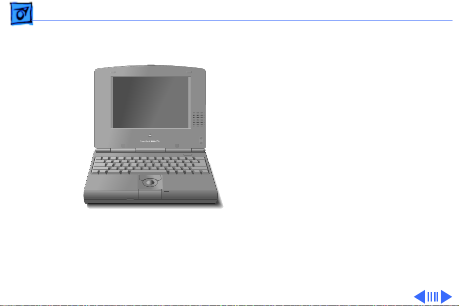
System Overview
PowerBook Duo
System
The PowerBook Duo system
includes the following
products:
• PowerBook 200 Series
computer, shown at left
(PowerBook Duo 210/
230/250/270c/280/
PowerBook Duo 210/230/250/270c/280/280c
280c)
• PowerBook 2300 Series
computer (PowerBook
Duo 2300c)
Page 4
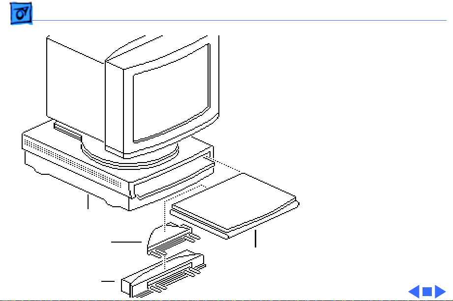
Basics System Overview - 2
• PowerBook Duo Floppy
Adapter
• PowerBook Duo Dock/
Duo Dock II/Duo DockPlus
• PowerBook Duo MiniDock
This manual includes
information about the
PowerBook 200 Series
computers and the floppy
adapter.
For information about the
Duo Dock/Duo Dock II/
Duo Dock Plus
Duo Floppy
Adapter
Duo MiniDock
Duo 210/230
250/270c
280/280c/
PowerBook 2300 Series,
Duo Docks, or the Duo
MiniDock, refer to the
appropriate PowerBook Duo
manual.
Page 5

Basics Repair Strategy - 3
Repair Strategy
Service the PowerBook 200 Series computers through
module exchange and parts replacement. Customers can
request on-site service from an Apple Authorized Service
Provider Plus (AASP+) Apple Assurance (US only), or
request a courier through the Apple Canada Technical
Answerline (Canada only). They can also choose carry-in
service from an AASP.
Ordering
Apple Service Providers planning to support the computer
systems covered in this manual may purchase Service
modules and parts to develop servicing capability. To order
parts, use the AppleOrder (US only) or ARIS (Canada only)
system and refer to “Service Price Pages.”
Page 6

Basics Repair Strategy - 4
Large businesses, universities, and K-12 accounts must
provide a purchase order on all transactions, including
orders placed through the AppleOrder (US only) or ARIS
(Canada only) system.
USA Ordering
US Service Providers not enrolled in AppleOrder may fax
their orders to Service Provider Support (512-908-
8125) or mail them to
Apple Computer, Inc.
Service Provider Support
MS 212-SPS
Austin, TX 78714-9125
For US inquiries, please call Service Provider Support at
800-919-2775 and select option #1.
Page 7

Basics Repair Strategy - 5
Canadian Ordering
Canadian Service Providers not enrolled in ARIS may fax
their orders to Service Provider Support in Canada
(1-800-903-5284). For Canadian inquiries, please call
Service Provider Support at 905-513-5782 and select
option #3.
Page 8

Basics Warranty/AppleCare/ARIS - 6
Warranty/AppleCare/ARIS
US Only
The PowerBook 200 Series computers are covered under the
Apple One-Year Limited Warranty. The AppleCare Service
Plan is also available for these products. Service Providers
are reimbursed for warranty and AppleCare repairs made to
these computers. For pricing information, refer to “Service
Price Pages.”
Canada Only
The PowerBook 200 Series computers are covered under
first-year AppleCare. The Extended AppleCare Service Plan
is also available for these products. Service Providers are
reimbursed for first-year warranty and Extended
AppleCare repairs made to these computers. For pricing
information, refer to “Service Price Pages.”
Page 9
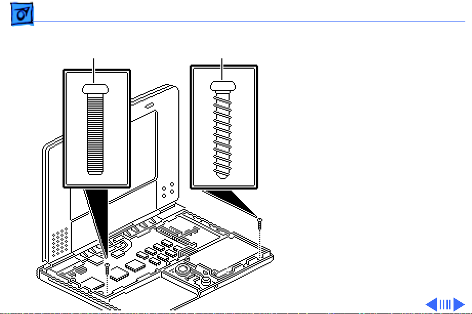
Basics Self-Threading Screws - 7
Machine Screw
Self-Threading Screw
Self-Threading Screws
Caution:
installed self-threading
screws could damage the
PowerBook Duo. Thread the
screws properly and do not
overtighten them.
Caution:
damage to the circuitry, do
not use magnetic
screwdrivers when working
on Apple systems.
Improperly
To prevent
Page 10

Basics Self-Threading Screws - 8
The PowerBook 200 systems use both machine screws and
self-threading screws. Be aware when you are replacing a
self-threading screw, and follow these guidelines:
• Never overtighten self-threading screws.
• Before tightening a self-threading screw, back the screw
off slightly to be sure it is threaded properly.
Page 11

Basics Self-Threading Screws - 9
Self-threading screws are
used to install the following
modules and replacement
parts:
• Hard drive
• Trackball assembly
• CPU stiffener and logic
board
CPU
Stiffener
Hard Drive
Trackball Assembly
Logic Board
Page 12

K
Service Source
Specifications
PowerBook 200 Series
Page 13

Specifications Introduction - 1
Introduction
You can also find specifications information for this product in the
Spec Database, which you can access in one of three ways:
— Launch it directly by double-clicking the Apple Spec Database
runtime alias at the top level of the Main Service Source CD.
— Select "Apple Spec Database" from the Service Source drop-
down main menu.
— Click the Acrobat toolbar icon for the database, which is near
the right end of the toolbar with the letters "SP."
Page 14

Specifications Processor - 2
Processor
CPU 210
CPU 230/250/270c
CPU 280/280c
Coprocessor (270c Only)
Motorola 68030 microprocessor
25 MHz
Motorola 68030 microprocessor
33 MHz
Motorola 68LC040 microprocessor
66/33 MHz
Motorola 68882 floating-point coprocessor
Page 15

Specifications Processor - 3
Addressing
32-bit internal registers
32-bit address/data bus supports 4 GB of address with justified
8-bit, 16-bit, and 32-bit data transactions
Page 16

Specifications Memory - 4
Memory
RAM 210/230/250
RAM 270c
RAM 280/280c
ROM
4 MB RAM soldered on the logic board
Expandable to 24 MB
Requires 70 ns or faster RAM chips
4 MB RAM soldered on the logic board
Expandable to 32 MB
Requires 70 ns or faster RAM chips
4 MB RAM soldered on the logic board
Expandable to 40 MB
Requires 70 ns or faster RAM chips
1 MB
Page 17

Specifications Memory - 5
PRAM
Clock/Calendar
256 bytes of parameter memory
CMOS custom chip supported by long-life (up to 2 years) lithium
battery
Page 18

Specifications Disk Storage - 6
Disk Storage
Floppy Drive
Hard Drive
External 1.4 MB floppy drive (same drive is used with
PowerBook 100)
Requires Duo Floppy Adapter or Duo MiniDock
2.5-in., internal, 17 mm high
Page 19

Specifications I/O Interfaces - 7
I/O Interfaces
Docking Connector
Serial
Modem
152-pin processor-direct slot (PDS connector for attaching
expansion devices
32-bit expansion bus
RS-422 serial port; mini DIN-8 connector
Optional internal modem/telephone jack
RJ-11 domestic; mini DIN-8 international
Page 20

Specifications I/O Devices - 8
I/O Devices
Keyboard
Trackball
Microphone
Built-in standard Apple keyboard
63 keys domestic; 64 keys ISO
Caps-locked LED
Soft power-on switch
2.5 mm travel, 18 mm vertical and horizontal pitch
Two-level tilt adjustment
19 mm diameter, dua button
Apple Desktop Bus (ADB) interface
Built-in electret, omnidirectional microphone
Page 21

Specifications Sound and Video - 9
Sound and Video
Sound Generator
Video Display 210/ 230
Apple sound chip provides four-voice/8-bit sound, sampled at 11
or 22 kHz
Monophonic sound in and sound out
9 in. (229 mm) diagonal screen
Flat-panel, film-compensated supertwist nematic (FSTN) liquid
crystal display
1, 2, and 4 bits per pixel
16 level grayscale at 4 bits per pixel
640 lines by 400 pixels
CCFL on-demand backlight
Adjustable brightness and contrast controls
Page 22

Specifications Sound and Video - 10
Video Display 250
Video Display 270c
Video Display 280
9 in. (229 mm) diagonal screen
Flat-panel, color, active-matrix, liquid crystal display
CCFL on-demand backlight
640 lines by 400 pixels; 16 shades of gray
9 in. (229 mm) diagonal screen
Flat-panel, color active-matrix, liquid crystal display
CCFL on-demand backlight
640 lines by 480 pixels; 8 bits; 256 colors
9 in. (229 mm) diagonal screen
Backlit, active-matrix, grayscale display
640 lines by 400 pixels; 16 shades of gray
Page 23

Specifications Sound and Video - 11
Video Display 280c
8.4 in. diagonal, backlit, active matrix color display
640 lines by 480 pixels for 256 colors, or 640 lines by 400
pixels for thousands of colors
Page 24

Specifications Electrical - 12
Electrical
Main Battery 210/ 230
Main Battery 250/ 270c
NiMH (nickel-metal-hydride), 0.95 Ah
Approximately 2-4 hours of usage before recharging (depending
upon use)
Recharge time: approximately 2 hours
500 power cycles capacity
NiMH (nickel-metal-hydride), 1.5 Ah
Approximately 2-3 hours of usage before recharging (depending
upon use)
Recharge time: approximately 2 hours
500 power cycles capacity
Uses 4/5 A size battery cells
Page 25

Specifications Electrical - 13
Main Battery 280/ 280c
PRAM Battery
Power Adapter
NiMH (nickel-metal-hydride), 1.6 Ah
Approximately 2-3 hours of usage before recharging (depending
upon use)
Recharge time: approximately 2 hours
500 power cycles capacity
3 V lithium backup battery
500 power cycles capacity
Input: 85-270 VAC line voltage, 47-63 Hz
Output: 24 VDC, 1.04 A
Can be used anywhere in the world with the appropriate power
cord
Page 26

Specifications Physical - 14
Physical
Dimensions 210/230/ 250/280
Dimensions 270c/ 280c
Weight 210/230/250/ 280
Weight 270c/280c
Height: 1.4 in. (36 mm)
Width: 8.5 in. (216 mm)
Depth: 10.9 in. (277 mm)
Height: 1.5 in. (36 mm)
Width: 8.5 in. (216 mm)
Depth: 10.9 in. (277 mm)
4.25 lb. (1.9 kg) with battery
4.8 lb. (2.1 kg) with battery
Page 27

Specifications Environmental - 15
Environmental
Operating Temperature
Storage Temperature
Relative Humidity
Operating Altitude
50–104° F (10–40° C)
-40 to 116° F (-40 to 47° C)
20–95% noncondensing
0–15,000 ft. (0–4722 m)
Page 28

Specifications Other - 16
Other
Express Modem
SCSI Disk Adapter
Internal 14,400-baud modem with fax send/receive capability at
9600 baud
300–14,400 bps data transmission rates
2400/4800/7200/9600 bps transmission rates
Full duplex operation; asynchronous or framed modes
Error correction: V.42 compliance (MNP2-4)
Data compression: V.42bis (4 to 1 compression) and MNP-5 (2
to 1 compression)
Requires 300K of system RAM
Built-in support for internal modem when in docking systems
Enables connection between PowerBook Duo computer and desktop
Macintosh (Duo system appears as a hard drive on desktop)
Requires Duo MiniDock
Page 29

K
Service Source
Troubleshooting
PowerBook 200 Series
Page 30

Troubleshooting General/ - 2
General
The Symptom Charts included in this chapter will help you
diagnose specific symptoms related to your product. Because cures
are listed on the charts in the order of most likely solution, try
the first cure first. Verify whether or not the product continues to
exhibit the symptom. If the symptom persists, try the next cure.
(
Note:
If you have replaced a module, reinstall the original
module before you proceed to the next cure.)
If you are not sure what the problem is, or if the Symptom Charts
do not resolve the problem, refer to the Flowchart for the product
family.
For additional assistance, contact Apple Technical Support.
Page 31

Troubleshooting Power Manager Reset/ - 3
Power Manager Reset
If a unit crashes or experiences power problems, reset the power
manager chip by pressing the rear power switch for 30-45
seconds.
If resetting the power manager chip does not solve the problem,
reset the code for the power manager chip by removing all power
sources and letting the unit sit for 10 minutes. (Take out the
battery and disconnect the AC adapter and the internal backup
battery.) This forces the PowerBook Duo to reload the power
manager code from the system software.
Page 32

Troubleshooting Symptom Charts/Startup - 4
Symptom Charts
Startup
RAM failure occurs
(eight-tone error
chord sequence
sounds after startup
chord)
Hardware failure
occurs (four-tone
error chord sequence
sounds after startup
chord)
1 Check RAM expansion card connection.
2 Replace RAM expansion card.
3 Replace logic board.
Note:
When replacing the logic board, check that the EMI clips
are securely attached to the CPU stiffener. The “CPU Stiffener”
topic in Take Apart helps you locate and identify the two EMI
clips. If both clips are not secure, replace the CPU stiffener.
1 Disconnect hard drive data cable and reboot system. If
startup sequence is normal, reseat cable and retest.
2 Replace hard drive.
3 If the system is connected to an external floppy drive,
disconnect drive and reboot system. If startup sequence is
Page 33

Troubleshooting Symptom Charts/Startup
normal, reseat cable and retest.
(Continued)
- 5
Startup
1 Replace floppy drive.
2 Replace logic board.
Note:
are securely attached to the CPU stiffener. The “CPU Stiffener”
topic in Take Apart helps you locate and identify the two EMI clips.
If both clips are not secure, replace the CPU stiffener.
(Continued)
When replacing the logic board, check that the EMI clips
Page 34

Troubleshooting Symptom Charts/Power - 6
Power
Screen is blank;
computer does not
respond
1 Simultaneously press <Command> <Control> <Power On> keys
to reset computer.
2 Connect power adapter and reboot computer in 3-4 minutes.
3 Try known-good, charged main battery.
4 Check all logic board cable connections.
5 Replace logic board.
Note:
When replacing the logic board, check that the EMI clips
are securely attached to the CPU stiffener. The “CPU Stiffener”
topic in Take Apart helps you locate and identify the two EMI clips.
If both clips are not secure, replace the CPU stiffener.
Page 35

Troubleshooting Symptom Charts/Power
(Continued)
- 7
After you remove
main battery, some
Control Panel
settings are different
Power adapter is
plugged in, but
battery DA does not
indicate charger is
connected
Power
Replace backup battery.
1 This is normal for fully charged battery.
2 Check power adapter connection.
3 Try known-good, charged main battery.
4 Try known-good power adapter.
5 Replace logic board.
Note:
are securely attached to the CPU stiffener. The “CPU Stiffener”
topic in Take Apart helps you locate and identify the two EMI clips.
If both clips are not secure, replace the CPU stiffener.
(Continued)
When replacing the logic board, check that the EMI clips
Page 36

Troubleshooting Symptom Charts/Power
(Continued)
- 8
Low-power warning
appears
Power
1 Recharge battery or attach power adapter.
2 Remove external devices.
3 Try known-good, charged main battery.
4 Try known-good power adapter.
5 Replace logic board.
Note:
are securely attached to the CPU stiffener. The “CPU Stiffener”
topic in Take Apart helps you locate and identify the two EMI clips.
If both clips are not secure, replace the CPU stiffener.
(Continued)
When replacing the logic board, check that the EMI clips
Page 37

Troubleshooting Symptom Charts/Power
(Continued)
- 9
Computer runs when
plugged into wall
outlet but not when
using battery power;
battery voltage is
within tolerance
Power
1 Replace main battery.
2 Replace logic board.
Note:
are securely attached to the CPU stiffener. The “CPU Stiffener”
topic in Take Apart helps you locate and identify the two EMI clips.
If both clips are not secure, replace the CPU stiffener.
(Continued)
When replacing the logic board, check that the EMI clips
Page 38

Troubleshooting Symptom Charts/Power
(Continued)
- 10
System powers off
unexpectedly, system
errors occur, or
system hangs up.
Symptoms usually
occur in these
situations: Keyboard
is used while
PowerBook Duo flip
feet are down,
PowerBook Duo is
inserted in Duo Dock,
or PowerBook Duo is
attached to MiniDock.
Power
Make sure that the logic board mounting screw that also serves as
a battery contact is installed. (Screw should be installed on
contact located on right side.)
(Continued)
Page 39

Troubleshooting Symptom Charts/Power
(Continued)
- 11
System powers down
unexpectedly, won’t
boot off battery, or
powers down
intermittently when
running off battery.
Or, battery won’t
charge.
Power
1 Make sure battery is good battery.
2 Use Duo battery contact alignment tool to check alignment of
(Continued)
battery contacts. If contacts are out of alignment, use tool to
realign them.
Page 40

Troubleshooting Symptom Charts/Video - 12
Video
Row or partial row of
pixels never comes
on or is always on
PowerBook Duo 210/230:
1 Check display cable connection.
2 Replace display.
3 Replace logic board.
4 Return computer to Apple.
PowerBook Duo 270c/280c:
5 Check display cable connection.
6 Replace display cable.
7 Replace display (CPRC/Int’l only).
8 Replace logic board.
9 Return computer to Apple.
Page 41

Troubleshooting Symptom Charts/Video
(Continued)
- 13
Thin white line is
always on at middle of
screen
Video
PowerBook Duo 210/230:
1 Adjust screen contrast.
2 For FSTN screens, a thin white line is normal.
PowerBook Duo 250:
3 Adjust screen contrast.
4 Replace display (CPRC/Int’l only) or return computer to
(Continued)
Apple.
Page 42

Troubleshooting Symptom Charts/Video
(Continued)
- 14
Display is very light
or totally white
Video
PowerBook Duo 210/230/250/280:
1 Adjust screen contrast.
2 Check logic board cable connections.
3 Duo 210/230: Replace display.
4 Duo 250/280: Replace display (CPRC/Int’l only).
5 Replace logic board.
(Continued)
Page 43

Troubleshooting Symptom Charts/Video
(Continued)
- 15
Video
PowerBook Duo 270c/280c:
1 Adjust screen contrast.
2 Check logic board cable connections.
3 Replace inverter board.
4 Replace display cable.
5 Replace display (CPRC/Int’l only).
6 Replace logic board.
7 Return computer to Apple.
(Continued)
Page 44

Troubleshooting Symptom Charts/Video
(Continued)
- 16
No display, but
computer appears to
operate correctly
Video
PowerBook Duo 210/230/250/280:
1 Adjust screen contrast.
2 Check logic board cable connections.
3 Connect power adapter.
4 Duo 210/230: Replace display.
5 Duo 250/280: Replace display (CPRC/Int’l only).
6 Replace logic board.
7 Return computer to Apple.
(Continued)
Page 45

Troubleshooting Symptom Charts/Video
(Continued)
- 17
Rainbow colors
visible from extreme
viewing angles
Video
PowerBook Duo 270c/280c:
1 Adjust screen contrast.
2 Check logic board cable connections.
3 Connect power adapter.
4 Replace inverter board
5 Replace display cable.
6 Replace display (CPRC/Int’l only).
7 Replace logic board.
8 Return computer to Apple
PowerBook Duo 210/230:
Such colors are normal for FSTN screens.
(Continued)
Page 46

Troubleshooting Symptom Charts/Video
(Continued)
- 18
Screen brightness is
not uniform
Display stopped
working or dimmed
but is fine now
Video
PowerBook Duo 210/230:
For FSTN screens, some irregularity in screen brightness is
normal. Adjust contrast and brightness to diminish effect.
PowerBook Duo 210/230:
Tighten loose display cable connectors. Otherwise, reaction is
normal for FSTN screens at extreme cold or hot temperatures
(approximately under 5 or over 40 degrees centigrade).
(Continued)
Page 47

Troubleshooting Symptom Charts/Video
(Continued)
- 19
Backlight does not
operate
Video
PowerBook Duo 210/230/250/280:
1 Check display cable connection.
2 Duo 210/230: Replace display.
3 Duo 250/280: Replace display (CPRC/Int’l only).
4 Replace logic board.
5 Return computer to Apple.
(Continued)
Page 48

Troubleshooting Symptom Charts/Video
(Continued)
- 20
Video
PowerBook Duo 270c/280c:
1 Check display cable connection.
2 Replace inverter board.
3 Replace display cable.
4 Replace display (CPRC/Int’l only).
5 Replace logic board.
6 Return computer to Apple.
Screen goes blank 1 Press any key or press <Wake Up> key to wake computer
2 Check display cable connection.
3 Replace cracked cable connectors.
(Continued)
from system sleep.
Page 49

Troubleshooting Symptom Charts/Video
(Continued)
- 21
Video
Screen flickers 1 Some flickering is normal for grayscale displays.
2 Set display to 1-bit mode (black and white) in Monitors
3 Check display cable connection.
4 Duo 210/230: Replace display.
5 Duo 250/280: Replace display (CPRC/Int’l only).
6 Replace logic board.
7 Return computer to Apple.
(Continued)
Control Panel.
Page 50

Troubleshooting Symptom Charts/Video
(Continued)
- 22
Pixel is always white
or always black
Video
1 PowerBook Duo 210 and 230: Replace display.
2 PowerBook Duo 250 and 280: If there are more than five
3 PowerBook Duo 270c and 280c, color active matrix display
(Continued)
voids (pixels that are always white), or two or more voids
within one inch of each other, replace display (CPRC/
international repairers only) or return computer to Apple.
only: Replace display (CPRC/ international repairers only)
or return computer to Apple.
Page 51

Troubleshooting Symptom Charts/External Floppy Drive - 23
External Floppy Drive
Audio and video
present, but external
drive does not operate
1 Check floppy-adapter-to-PowerBook connection.
2 Try known-good floppy disk.
3 Check floppy drive cable connection.
4 Replace floppy drive cable.
5 Replace floppy adapter.
6 Replace floppy drive.
7 Replace logic board.
Note:
When replacing the logic board, check that the EMI clips
are securely attached to the CPU stiffener. The “CPU Stiffener”
topic in Take Apart helps you locate and identify the two EMI clips.
If both clips are not secure, replace the CPU stiffener.
Page 52

Troubleshooting Symptom Charts/External Floppy Drive
(Continued)
- 24
Disk ejects while
booting; display
shows Mac icon with
blinking X
External Floppy Drive
1 Try known-good system disk.
2 Verify that trackball or mouse button is not stuck.
3 Check floppy drive cable connection.
4 Replace floppy drive cable.
5 Replace floppy adapter.
6 Replace floppy drive.
7 Replace logic board.
Note:
When replacing the logic board, check that the EMI clips
are securely attached to the CPU stiffener. The “CPU Stiffener”
topic in Take Apart helps you locate and identify the two EMI clips.
If both clips are not secure, replace the CPU stiffener.
(Continued)
Page 53

Troubleshooting Symptom Charts/External Floppy Drive
(Continued)
- 25
External Floppy Drive
Disk does not eject 1 Switch off system and hold mouse or trackball button down
while you switch system on.
2 Insert straightened paper clip into hole next to drive opening
to eject disk.
3 Check floppy drive cable connection.
4 Replace floppy drive cable.
5 Replace floppy adapter.
6 Replace floppy drive.
7 Replace logic board.
Note:
When replacing the logic board, check that the EMI clips
are securely attached to the CPU stiffener. The “CPU Stiffener”
topic in Take Apart helps you locate and identify the two EMI clips.
If both clips are not secure, replace the CPU stiffener.
(Continued)
Page 54

Troubleshooting Symptom Charts/External Floppy Drive
(Continued)
- 26
Disk initialization
fails
Read/write/copy
error
External Floppy Drive
1 Try known-good floppy disk.
2 Check floppy drive cable connection.
3 Replace floppy drive cable.
4 Replace floppy adapter.
5 Replace floppy drive.
1 Try known-good floppy disk.
2 Check floppy drive cable connection.
3 Replace floppy drive cable.
4 Replace floppy adapter.
5 Replace floppy drive.
(Continued)
Page 55

Troubleshooting Symptom Charts/Hard Drive - 27
Hard Drive
Internal hard drive
does not operate
1 Check internal hard drive cable connection.
2 Replace internal hard drive cable.
3 Run Macintosh Hard Disk Test.
4 Use HD SC Setup to reinitialize drive.
5 Replace internal hard drive.
6 Replace logic board.
Note:
When replacing the logic board, check that the EMI clips
are securely attached to the CPU stiffener. The “CPU Stiffener”
topic in Take Apart helps you locate and identify the two EMI clips.
If both clips are not secure, replace the CPU stiffener.
Page 56

Troubleshooting Symptom Charts/Peripherals - 28
Peripherals
Cursor does not move
when you are using
trackball
1 Simultaneously press <Command> <Control> <Power On> keys
to reset computer.
2 Clean ball and rollers of trackball.
3 Make sure display switch cable and battery cable are not
impeding trackball.
4 Check logic board cable connections.
5 Replace trackball.
6 Replace logic board.
Note:
When replacing the logic board, check that the EMI clips
are securely attached to the CPU stiffener. The “CPU Stiffener”
topic in Take Apart helps you locate and identify the two EMI clips.
If both clips are not secure, replace the CPU stiffener.
Page 57

Troubleshooting Symptom Charts/Peripherals
(Continued)
- 29
Cursor intermittently
does not move or
moves erratically
Peripherals
1 Clean ball and rollers of trackball.
2 Replace trackball.
3 Replace logic board.
Note:
When replacing the logic board, check that the EMI clips
are securely attached to the CPU stiffener. The “CPU Stiffener”
topic in Take Apart helps you locate and identify the two EMI clips.
If both clips are not secure, replace the CPU stiffener.
(Continued)
Page 58

Troubleshooting Symptom Charts/Peripherals
Peripherals (Continued)
(Continued)
- 30
Cursor moves, but
clicking trackball
button has no effect
1 Simultaneously press <Command> <Control> <Power On> keys
to reset computer.
2 Check logic board cable connections.
3 Replace trackball.
4 Replace logic board.
Note: When replacing the logic board, check that the EMI clips
are securely attached to the CPU stiffener. The “CPU Stiffener”
topic in Take Apart helps you locate and identify the two EMI clips.
If both clips are not secure, replace the CPU stiffener.
Page 59

Troubleshooting Symptom Charts/Peripherals (Continued) - 31
Peripherals (Continued)
No response to any
key on keyboard
1 Press <Power On> key or power button.
2 Adjust Battery Conservation setting in PowerBook Control
Panel.
3 Check keyboard cable connection.
4 If you are using floppy adapter and external keyboard,
replace keyboard cable.
5 Replace floppy adapter.
6 Replace keyboard.
7 Replace logic board.
Note: When replacing the logic board, check that the EMI clips
are securely attached to the CPU stiffener. The “CPU Stiffener”
topic in Take Apart helps you locate and identify the two EMI clips.
If both clips are not secure, replace the CPU stiffener.
Page 60

Troubleshooting Symptom Charts/Peripherals (Continued) - 32
Peripherals (Continued)
Cursor does not move
when you are using
floppy adapter and
mouse
1 Check floppy adapter and mouse connections.
2 Simultaneously press <Command> <Control> <Power On> keys
to reset computer.
3 Clean mouse ball and inside mouse.
4 Replace mouse.
5 Replace floppy adapter.
6 Replace logic board.
Note: When replacing the logic board, check that the EMI clips
are securely attached to the CPU stiffener. The “CPU Stiffener”
topic in Take Apart helps you locate and identify the two EMI clips.
If both clips are not secure, replace the CPU stiffener.
Page 61

Troubleshooting Symptom Charts/Peripherals (Continued) - 33
Peripherals (Continued)
Known-good serial
printer does not print
1 Verify that System is 7.1 or later.
2 Verify that Chooser and Control Panel settings are correct.
3 Check cables.
4 Replace printer interface cable.
5 Try known-good printer.
6 Replace logic board.
Note: When replacing the logic board, check that the EMI clips
are securely attached to the CPU stiffener. The “CPU Stiffener”
topic in Take Apart helps you locate and identify the two EMI clips.
If both clips are not secure, replace the CPU stiffener.
Page 62

Troubleshooting Symptom Charts/Peripherals (Continued) - 34
Peripherals (Continued)
Known-good
networked printer
does not print
1 Verify that System is 7.1 or later.
2 Verify that Chooser and Control Panel settings are correct.
3 Check cables.
4 Replace printer interface cable.
5 Try known-good printer. If printer works, troubleshoot
network.
6 Replace logic board.
Note: When replacing the logic board, check that the EMI clips
are securely attached to the CPU stiffener. The “CPU Stiffener”
topic in Take Apart helps you locate and identify the two EMI clips.
If both clips are not secure, replace the CPU stiffener.
Page 63

Troubleshooting Symptom Charts/Peripherals (Continued) - 35
Peripherals (Continued)
Device connected to
mini-DIN-8 port
does not work
1 Verify that External Modem is selected in PowerBook Control
Panel.
2 Verify that System is 7.1 or later.
3 Check cables.
4 Test device with known-good computer.
5 Replace logic board.
Note: When replacing the logic board, check that the EMI clips
are securely attached to the CPU stiffener. The “CPU Stiffener”
topic in Take Apart helps you locate and identify the two EMI clips.
If both clips are not secure, replace the CPU stiffener.
Page 64

Troubleshooting Symptom Charts/Peripherals (Continued) - 36
Peripherals (Continued)
I/O devices are
unrecognized or
garbage is
transmitted or
received
Space bar is hard to
press and/or does not
work
1 Verify that System is 7.1 or later.
2 Check floppy adapter and cable connections.
3 Test device with known-good computer.
4 Replace logic board.
Note: When replacing the logic board, check that the EMI clips
are securely attached to the CPU stiffener. The “CPU Stiffener”
topic in Take Apart helps you locate and identify the two EMI clips.
If both clips are not secure, replace the CPU stiffener.
Loosen keyboard screws. Over-tightening can warp keyboard and
restrict movement of space bar.
Page 65

Troubleshooting Symptom Charts/Internal Modem - 37
Internal Modem
Internal modem
options do not appear
in CDEV
1 Verify that System is 7.1 or later.
2 Remove and reseat modem card.
3 Replace modem card.
4 Replace logic board.
Note: When replacing the logic board, check that the EMI clips
are securely attached to the CPU stiffener. The “CPU Stiffener”
topic in Take Apart helps you locate and identify the two EMI clips.
If both clips are not secure, replace the CPU stiffener.
Page 66

Troubleshooting Symptom Charts/ - 38
Internal Modem (Continued)
Modem does not
respond properly to
AT command set
instructions
1 Verify that baud rate and data format settings of
communications application are compatible with internal
modem and remote modem.
2 Check phone cord connection and operation.
3 Verify that System is 7.1 or later.
4 Remove and reseat modem card.
5 Replace modem card.
Page 67

Troubleshooting Symptom Charts/Internal Modem (Continued) - 39
Internal Modem (Continued)
Strange mix of
characters appears
on screen
1 Verify that baud rate and data format settings of
communications application are compatible with internal
modem and remote modem.
2 Check phone cord connection and operation.
3 Verify that System is 7.1 or later.
4 Remove and reseat modem card.
5 Replace modem card.
6 Replace logic board.
Note: When replacing the logic board, check that the EMI clips
are securely attached to the CPU stiffener. The “CPU Stiffener”
topic in Take Apart helps you locate and identify the two EMI clips.
If both clips are not secure, replace the CPU stiffener.
Page 68

Troubleshooting Symptom Charts/Internal Modem (Continued) - 40
Internal Modem (Continued)
Modem interferes
with system sound
1 Remove and reseat modem card.
2 Replace modem card.
3 Replace logic board.
Note: When replacing the logic board, check that the EMI clips
are securely attached to the CPU stiffener. The “CPU Stiffener”
topic in Take Apart helps you locate and identify the two EMI clips.
If both clips are not secure, replace the CPU stiffener.
Page 69

Troubleshooting Symptom Charts/Internal Modem (Continued) - 41
Internal Modem (Continued)
Modem does not
respond to incoming
call
1 If computer is in sleep mode, verify that “Answer calls” is
selected in PowerBook Control Panel.
2 Check phone cord connection and operation.
3 Replace modem card.
4 Replace logic board.
Note: When replacing the logic board, check that the EMI clips
are securely attached to the CPU stiffener. The “CPU Stiffener”
topic in Take Apart helps you locate and identify the two EMI clips.
If both clips are not secure, replace the CPU stiffener.
Page 70

Troubleshooting Symptom Charts/Internal Modem (Continued) - 42
Internal Modem (Continued)
Modem has no sound
output
Modem connects but
does not communicate
with remote modem
1 Verify that Control Panel volume setting is 1 or above.
2 Replace modem card.
3 Replace logic board.
Note: When replacing the logic board, check that the EMI clips
are securely attached to the CPU stiffener. The “CPU Stiffener”
topic in Take Apart helps you locate and identify the two EMI clips.
If both clips are not secure, replace the CPU stiffener.
1 Verify that remote modem needs error correction (error
correction is internal modem default).
2 Type AT &Q0 to disable error correction.
Page 71

Troubleshooting Symptom Charts/Miscellaneous - 43
Miscellaneous
Screen goes blank and
computer shuts down
every few minutes
Application seems to
run slower after few
seconds
Hard drive is slow to
respond, or screen
goes blank too often
Adjust Battery Conservation setting in Control Panel or connect
power adapter.
1 Adjust Battery Conservation Options setting in Control Panel
or connect power adapter.
2 Connect power adapter.
Adjust Battery Conservation setting in Control Panel or connect
power adapter.
Page 72

Troubleshooting Symptom Charts/Miscellaneous (Continued) - 44
Miscellaneous (Continued)
No sound from
speaker
PowerBook Duo 210/230/250/280:
1 Verify that Control Panel volume setting is 1 or above.
2 Check display cable connection.
3 Duo 210/230: Replace display.
4 Duo 250/280: Replace display (CPRC/Int’l Only).
5 Replace logic board.
Page 73

Troubleshooting Symptom Charts/Miscellaneous (Continued) - 45
Miscellaneous (Continued)
PowerBook Duo 270c/280c:
1 Verify that Control Panel volume setting is 1 or above.
2 Check display cable connection.
3 Replace display cable.
4 Replace speaker assembly.
5 Replace logic board.
6 Return computer to Apple.
Red light on battery
recharger; battery
won’t charge
Replace Type 1 recharger with Type 2 recharger. Or replace
Type 2 or Type 3 battery with Type 1 battery.
Note: Use only Type 1 batteries in a Type 1 battery recharger;
Type 2 or Type 3 batteries will not charge. You can charge Type 1,
Type 2, or Type 3 batteries in a Type 2 battery recharger.
Page 74

K
Service Source
T ak e Apart
PowerBook 200 Series
Page 75

Take Apart Main Battery - 1
Main Battery
Before you begin,
disconnect the power
adapter.
Main Battery
Release Button
Caution:
disconnect the power adapter
and remove the main battery
before attempting takeapart procedures, you could
short out the logic board.
1 Depress the release
2 Pull out the main
If you fail to
button and slide open the
battery door.
battery.
Page 76
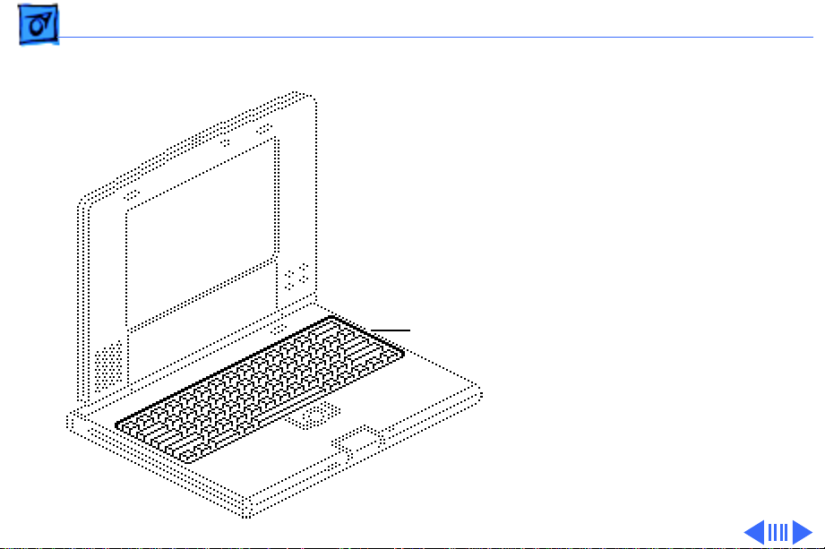
Take Apart Keyboard - 2
Keyboard
Before you begin, do the
following:
• Disconnect the power
adapter
• Remove the main battery
Note:
The following tools
are required to disassemble
Keyboard
a PowerBook Duo system:
• T-8 torx driver
• T-10 torx driver
• IC extractor
• Jeweler’s flat-blade
screwdriver
• Duo battery contact
alignment tool
Page 77

Take Apart Keyboard - 3
Caution:
Duo contains CMOS devices
that are very susceptible to
ESD damage. To prevent
damage, wear a grounding
wriststrap. Review the ESD
precautions in Bulletins/
Safety.
Caution:
cables are fragile and easily
torn or damaged. Handle all
cables with care.
The PowerBook
PowerBook Duo
Page 78

Take Apart Keyboard - 4
Note:
If you are removing
the keyboard only, you do
not need to remove the case
screw nearest the front of
the unit.
1 Close, latch, and turn
over the computer.
Remove the four case
screws from the bottom
of the computer.
Page 79

Take Apart Keyboard - 5
Replacement Caution:
Don’t overtighten the
keyboard screws.
Overtightening them could
warp the keyboard and
restrict key movement.
After replacing the screws,
always check the keys and
space bar to make sure they
work.
Page 80

Take Apart Keyboard - 6
2 Turn the computer
upright and open the
display.
Cables
Palm Rest
Caution:
Handle the
keyboard carefully to avoid
tearing cables connected
between the keyboard and
the logic board.
3 Carefully tilt the
computer and lift out
the keyboard. Turn the
keyboard over and place
it on the palm rest.
Page 81

Take Apart Keyboard - 7
4 Using a jeweler’s
screwdriver, push out
the release tabs and
remove the two keyboard
cables.
5 Set aside the keyboard.
Release Tabs
Cables
Page 82

Take Apart End Clutch Covers - 8
End Clutch Covers
Before you begin, do the
following:
• Disconnect the power
adapter
• Remove the main battery
Note:
End Clutch
Cover
End
Clutch
Cover
The end clutch covers
are disposable. If you break
or cosmetically damage the
covers, replace them.
Page 83

Take Apart End Clutch Covers - 9
1 Using a jeweler’s
screwdriver, push off
the left and right end
clutch covers.
End Clutch Cover
End
Clutch
Cover
Page 84

Take Apart Top Case - 10
Top Case
Before you begin, do the
following:
• Disconnect the power
adapter
• Remove the main battery
• Remove the keyboard
• Remove the end clutch
covers
Top Case
Page 85

Take Apart Top Case - 11
Caution:
Duo contains CMOS devices
that are very susceptible to
ESD damage. To prevent
damage, wear a grounding
wriststrap. Review the ESD
precautions in Bulletins/
Safety.
The PowerBook
Page 86
Take Apart Top Case - 12
Top Case
Interlocking Tabs
Caution:
The top case is
secured to the chassis by a
snap at the left corner of the
case and by four
interlocking tabs along the
front. Failure to unlock the
four interlocking case tabs
could damage the top case.
1 Raise the bottom left
corner of the top case
and release the case
snap.
2 Slide the top case off the
four interlocking tabs.
Page 87

Take Apart Top Case - 13
3 Remove the two rubber
bumpers from the
chassis.
Rubber
Bumper
Notch
Notch
Rubber
Bumper
Replace the rubber bumpers
with the notched ends aligned
as shown.
Page 88

Take Apart Hard Drive - 14
Hard Drive
Before you begin, do the
following:
• Disconnect the power
adapter
• Remove the main battery
• Remove the keyboard
• Remove the end clutch
covers
• Remove the top case
Hard Drive
Page 89

Take Apart Hard Drive - 15
Caution:
Duo contains CMOS devices
that are very susceptible to
ESD damage. To prevent
damage, wear a grounding
wriststrap. Review the ESD
precautions in Bulletins/
Safety.
Caution:
are fragile and easily torn
or damaged. Handle all
cables with care.
The PowerBook
PowerBook cables
Page 90

Take Apart Hard Drive - 16
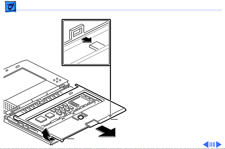
1 Remove the three self-
threading screws that
secure the hard drive to
the CPU stiffener.
2 Using an IC extractor,
disconnect the hard drive
cable.
EMI Shield
Hard Drive Cable
Replacement Note:
Before
replacing the hard drive
mounting screws, place the
hard drive cable beneath the
EMI shield.
Page 91

Take Apart Hard Drive - 17
3 Pull back the EMI shield
and lift out the hard
Hard Drive
EMI Shield
drive.
Page 92
Take Apart Hard Drive - 18
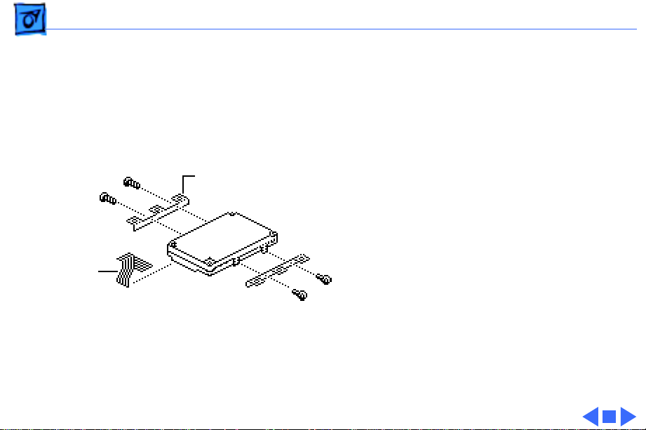
Note:
Remove the mounting
brackets only if you are
returning a defective drive
to Apple.
Note:
On early production
Mounting Brackets
units, Phillips screws
secure the mounting
brackets to the hard drive.
4 Using a T-8 torx driver,
Hard Drive
Cable
remove the four screws
and the two mounting
brackets from the hard
drive.
5 Disconnect the hard
drive cable.
Page 93

Take Apart Backup Battery - 19
Backup Battery
Before you begin, do the
following:
• Disconnect the power
adapter
• Remove the main battery
• Remove the keyboard
• Remove the end clutch
covers
• Remove the top case
Backup Battery
Page 94

Take Apart Backup Battery - 20
Caution:
Duo contains CMOS devices
that are very susceptible to
ESD damage. To prevent
damage, wear a grounding
wriststrap. Review the ESD
precautions in Bulletins/
Safety.
Caution:
are fragile and easily torn
or damaged. Handle all
cables with care.
The PowerBook
PowerBook cables
Page 95

Take Apart Backup Battery - 21
1 Remove the backup
battery from the
trackball assembly.
2 Carefully disconnect the
backup battery cable
Backup
Battery
Cable
Backup Battery
Trackball Assembly
from the logic board.
Page 96

Take Apart Trackball - 22
Trackball
Before you begin, do the
following:
• Disconnect the power
adapter
• Remove the main battery
• Remove the keyboard
• Remove the end clutch
covers
• Remove the top case
• Remove the backup
battery
Trackball
Page 97

Take Apart Trackball - 23
Caution:
Duo contains CMOS devices
that are very susceptible to
ESD damage. To prevent
damage, wear a grounding
wriststrap. Review the ESD
precautions in Bulletins/
Safety.
Caution:
are fragile and easily torn
or damaged. Handle all
cables with care.
The PowerBook
PowerBook cables
Page 98

Take Apart Trackball - 24
1 Remove the two self-
threading screws that
secure the trackball
assembly to the chassis.
2 Using an IC extractor,
disconnect the trackball
cable.
3 Lift out the trackball
assembly.
Trackball Assembly
Trackball Cable
Page 99

Take Apart Trackball - 25
Trackball
Display
Switch
Cable
Backup
Battery
Cable
Replacement Note:
When
replacing the trackball
assembly, be sure to route
the display switch cable and
the backup battery cable
around the trackball.
Page 100

Take Apart Center Clutch Cover - 26
Center Clutch Cover
Before you begin, do the
following:
Center Clutch
Cover
• Disconnect the power
adapter
• Remove the main battery
• Remove the keyboard
• Remove the end clutch
covers
• Remove the top case
 Loading...