

Page 1

MP1900A
this
Signal Quality Analyzer-R
Operation Manual
Ninth Edition
For safety and warning information, please read
manual before attempting to use the equipment.
Keep this manual with the equipment.
ANRITSU CORPORATION
Document No.: M-W3911AE-9.0
Page 2
Safety Symbols
DANGER
WARNING
CAUTION
To prevent the risk of personal injury or loss related to equipment malfunction, Anritsu Corporation uses the
following safety symbols to indicate safety-related information. Ensure that you clearly understand the meanings of
the symbols BEFORE using the equipment. Some or all of the following symbols may be used on all Anritsu
equipment. In addition, there may be other labels attached to products that are not shown in the diagrams in this
manual.
Symbols used in manual
This indicates a very dangerous procedure that could result in serious injury or
death if not performed properly.
This indicates a hazardous procedure that could result in serious injury or death if
not performed properly.
This indicates a hazardous procedure or danger that could result in light-to-severe
injury, or loss related to equipment malfunction, if proper precautions are not taken.
Safety Symbols Used on Equipment and in Manual
The following safety symbols are used inside or on the equipment near operation locations to provide information
about safety items and operation precautions. Ensure that you clearly understand the meanings of the symbols and
take the necessary precautions BEFORE using the equipment.
This indicates an obligatory safety precaution. The obligatory operation is
This indicates a warning or caution. The contents are indicated symbolically in or
This indicates a note. The contents are described in the box.
These indicate that the marked part should be recycled.
This indicates a prohibited operation. The prohibited operation is indicated
symbolically in or near the barred circle.
indicated symbolically in or near the circle.
near the triangle.
MP1900A
Signal Quality Analyzer-R
Operation Manual
19 June 2017 (First Edition)
12 February 2021 (Ninth Edition)
Copyright © 2017-2021, ANRITSU CORPORATION.
All rights reserved. No part of this manual may be reproduced without the prior written permission of the
publisher.
The operational instructions of this manual may be changed without prior notice.
Printed in Japan
ii
Page 3
For Safety
Electric Shock
Repair
Calibration
WARNING
● ALWAYS refer to the operation manual when working near locations
at which the alert mark shown on the left is attached. If the advice in
the operation manual is not followed, there is a risk of personal injury
or reduced equipment performance. The alert mark shown on the left
may also be used with other marks and descriptions to indicate other
dangers.
● Overvoltage Category
This equipment complies with overvoltage category II defined in IEC
61010. DO NOT connect this equipment to the power supply of
overvoltage category III or IV.
● To ensure that the equipment is grounded, always use the supplied
3-pin power cord, and insert the plug into an outlet with a ground
terminal. If power is supplied without grounding the equipment, there
is a risk of receiving a severe or fatal electric shock or causing
damage to the internal components.
● Only qualified service personnel with a knowledge of electrical fire and
shock hazards should service this equipment. This equipment cannot
be repaired by the operator. DO NOT attempt to remove the
equipment covers or unit covers or to disassemble internal
components. There are high-voltage parts in this equipment
presenting a risk of severe injury or fatal electric shock to untrained
personnel. In addition, there is a risk of damage to precision
components.
● The performance-guarantee seal verifies the integrity of the equipment.
To ensure the continued integrity of the equipment, only Anritsu
service personnel, or service personnel of an Anritsu sales
representative, should break this seal to repair or calibrate the
equipment. Be careful not to break the seal by opening the
equipment or unit covers. If the performance-guarantee seal is
broken by you or a third party, the performance of the equipment
cannot be guaranteed.
iii
Page 4
For Safety
LCD
Falling Over
WARNING
● This equipment should always be positioned in the correct manner. If
the cabinet is turned on its side, etc., it will be unstable and may be
damaged if it falls over as a result of receiving a slight mechanical
shock.
Always set up the equipment in a position where the power switch
can be reached without difficulty.
● This equipment uses a Liquid Crystal Display (LCD). DO NOT subject
the equipment to excessive force or drop it. If the LCD is subjected to
strong mechanical shock, it may break and liquid may leak.
This liquid is very caustic and poisonous.
DO NOT touch it, ingest it, or get in your eyes. If it is ingested
accidentally, spit it out immediately, rinse your mouth with water and
seek medical help. If it enters your eyes accidentally, do not rub your
eyes, rinse them with clean running water and seek medical help. If
the liquid gets on your skin or clothes, wash it off carefully and
thoroughly with soap and water.
iv
Page 5
For Safety
Check Terminal
CAUTION
Cleaning
Static Sensitive
● Always remove the main power cable from the power outlet before
cleaning dust around the power supply and fan.
- Clean the power inlet regularly. If dust accumulates around the
power pins, there is a risk of fire.
- Keep the cooling fan clean so that the ventilation holes are not
obstructed. If the ventilation is obstructed, the cabinet may
overheat and catch fire.
● Never input a signal of more than the indicated value between the
measured terminal and ground. Input of an excessive signal may
damage the equipment.
● Always take the following anti-static measures to prevent the internal
circuit from being damaged when using a connector indicated by the
symbol shown on the left.
- Wear a wrist strap connected to the ground terminal of this
equipment.
- Connect the ground wires of this equipment, external measuring
instruments and DUT before connecting a coaxial cable.
- Eliminate static electricity charged between the cores and outer
conductors of an external device and the coaxial cable, before
connecting this equipment and the external device.
● This is a heavy object. When lifting and moving this equipment,
always work in a group of two or more, or use a trolley. There is a
risk of back injury, if this equipment is lifted or moved by one person.
v
Page 6
For Safety
External
Storage Media
SSD
CAUTION
The MP1900A saves data and programs to an external storage media
which has USB interface.
If this media is mishandled or becomes faulty, important data may be
lost. It is recommended to periodically back up all important data and
programs to protect them from being lost accidentally.
Anritsu will not be held responsible for lost data.
Pay careful attention to the following points.
● Never remove the memory card from the equipment while it is being
accessed.
● The memory card may be damaged by static electric charges.
● Anritsu has thoroughly tested all external storage media shipped with
this equipment. Users should note that external storage media not
shipped with this equipment may not have been tested by Anritsu, thus
Anritsu cannot guarantee the performance or suitability of such media.
The equipment is equipped with a SSD (Solid State Drive) from which,
as with any hard disk, data may be lost under certain conditions. It is
recommended to periodically back up all important data and programs
to protect them from being lost accidentally.
Anritsu will not be held responsible for lost data.
To reduce the possibility of data loss, particular attention should be
given to the following points.
● The equipment should only be used within the recommend
temperature range, and should not be used in locations where the
temperature may fluctuate suddenly.
● Always follow the guidelines to ensure that the equipment is set up in
the specified manner.
● Always ensure that the fans at the rear and side of the equipment
are not blocked or obstructed in any way.
● Exercise care not to bang or shake the equipment whilst the power is
on.
● Never disconnect the mains power at the plug or cut the power at the
breaker with the equipment turned on.
vi
Page 7
For Safety
Lifetime of Parts
Use in a
E
Use in
Atmospheres
CAUTION
Residential
nvironment
Corrosive
The life span of certain parts used in this equipment is determined by the
operating time or the power-on time. Due consideration should be given
to the life spans of these parts when performing continuous operation
over an extended period. The safety of the equipment cannot be
guaranteed if component parts are used beyond their life spans. These
parts must be replaced at the customer's expense even if within the
guaranteed period described in Warranty at the beginning of this manual.
For details on life-span, refer to the corresponding section in this
manual.
Parts with operating time-dependent life span: LCD backlight
(40,000 hours)
This equipment is designed for an industrial environment.
In a residential environment, this equipment may cause radio
interference in which case the user may be required to take adequate
measures.
Exposure to corrosive gases such as hydrogen sulfide, sulfurous acid,
and hydrogen chloride will cause faults and failures.
Note that some organic solvents release corrosive gases.
vii
Page 8

Equipment Certificate
Anritsu Corporation certifies that this equipment was tested before shipment
using calibrated measuring instruments with direct traceability to public
testing organizations recognized by national research laboratories, including
the National Institute of Advanced Industrial Science and Technology, and
the National Institute of Information and Communications Technology, and
was found to meet the published specifications.
Anritsu Warranty
Anritsu Corporation will repair this equipment free-of-charge if a malfunction
occurs within one year after shipment due to a manufacturing fault, and
software bug fixes will be performed in accordance with the separate
Software End-User License Agreement, provide, however, that Anritsu
Corporation will deem this warranty void when:
● The fault is outside the scope of the warranty conditions separately
described in the operation manual.
● The fault is due to mishandling, misuse, or unauthorized modification or
repair of the equipment by the customer.
● The fault is due to severe usage clearly exceeding normal usage.
● The fault is due to improper or insufficient maintenance by the customer.
● The fault is due to natural disaster, including fire, wind or flood,
earthquake, lightning strike, or volcanic ash, etc.
● The fault is due to damage caused by acts of destruction, including civil
disturbance, riot, or war, etc.
● The fault is due to explosion, accident, or breakdown of any other
machinery, facility, or plant, etc.
● The fault is due to use of non-specified peripheral or applied equipment
or parts, or consumables, etc.
● The fault is due to use of a non-specified power supply or in a
non-specified installation location.
● The fault is due to use in unusual environments
● The fault is due to activities or ingress of living organisms, such as
insects, spiders, fungus, pollen, or seeds.
In addition, this warranty is valid only for the original equipment purchaser. It
is not transferable if the equipment is resold.
Anritsu Corporation shall assume no liability for damage or financial loss of
the customer due to the use of or a failure to use this equipment, unless the
damage or loss is caused due to Anritsu Corporation’s intentional or gross
(Note)
.
viii
Page 9

negligence.
Note:
For the purpose of this Warranty, "unusual environments" means use:
● In places of direct sunlight
● In dusty places
● Outdoors
● In liquids, such as water, oil, or organic solvents, and medical fluids, or
places where these liquids may adhere
● In salty air or in place chemically active gases (sulfur dioxide, hydrogen
sulfide, chlorine, ammonia, nitrogen dioxide, or hydrogen chloride etc.)
are present
● In places where high-intensity static electric charges or electromagnetic
fields are present
● In places where abnormal power voltages (high or low) or instantaneous
power failures occur
● In places where condensation occurs
● In the presence of lubricating oil mists
● In places at an altitude of more than 2,000 m
● In the presence of frequent vibration or mechanical shock, such as in
cars, ships, or airplanes
Anritsu Corporation Contact
In the event of this equipment malfunctions, please contact an Anritsu
Service and Sales office. Contact information can be found on the last page
of the printed version of this manual, and is available in a separate file on the
PDF version.
ix
Page 10

This product and its manuals may require an Export License/Approval by
the Government of the product's country of origin for re-export from your
country.
Before re-exporting the product or manuals, please contact us to confirm
whether they are export
W
controlled items, the products/manuals need
to be broken/shredded so as not to be unlawfully used for military purpose.
This product contains a
Perchlorate Material
www.dtsc.ca.gov/hazardouswaste/perchlorate
Notes On Export Management
-controlled items or not.
hen you dispose of export-
FOR CALIFORNIA USA ONLY
CR Coin Lithium Battery which contains
– special handling may apply; See
x
Page 11
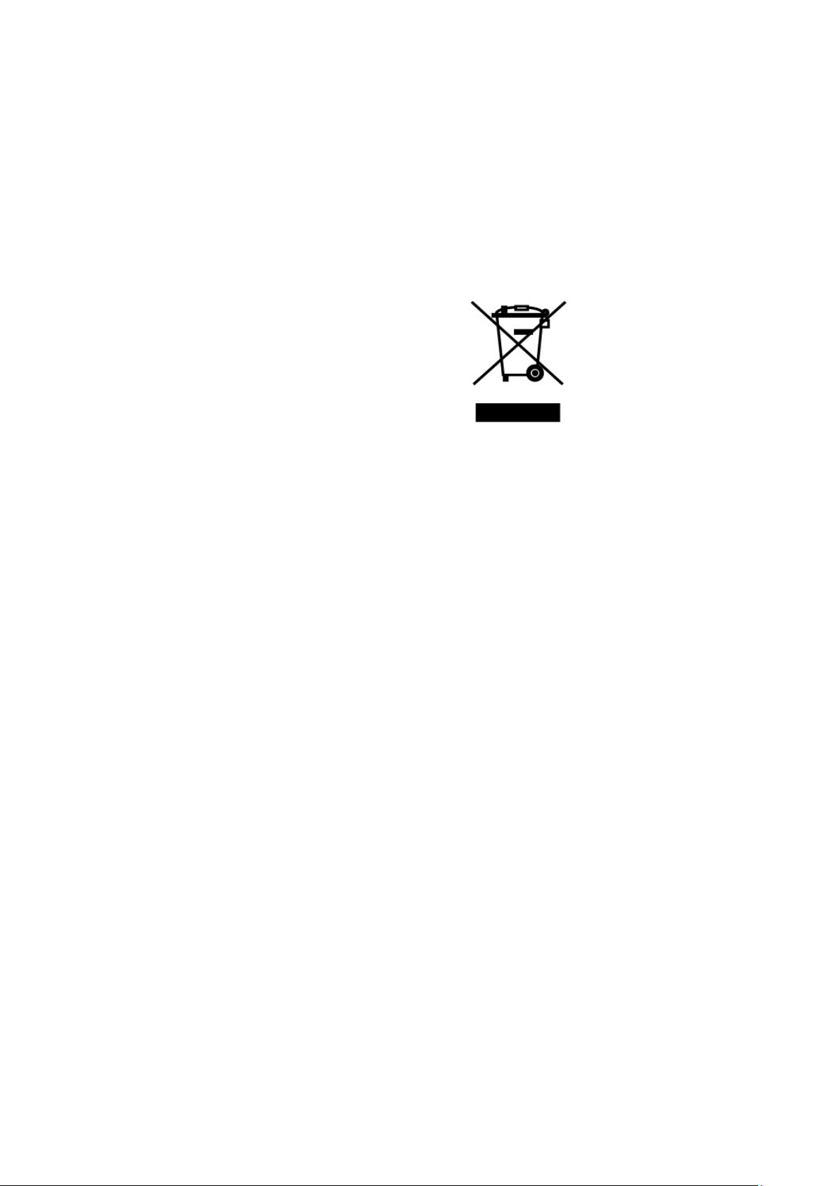
Crossed-out Wheeled Bin Symbol
Equipment marked with the Crossed-out Wheeled Bin Symbol complies with
council directive 2012/19/EU (the “WEEE Directive”) in European Union.
For Products placed on the EU market after August 13, 2005, please contact
your local Anritsu representative at the end of the product's useful life to
arrange disposal in accordance with your initial contract and the local law.
xi
Page 12

Software End-User License Agreement (EULA)
Please carefully read and accept this Software End-User License Agreement (hereafter this EULA)
before using (includes executing, copying, installing, registering, etc.) this Software (includes programs,
databases, scenarios, etc., used to operate, set, etc., Anritsu electronic equipment, etc.). By using this
Software, you shall be deemed to have agreed to be bound by the terms of this EULA, and Anritsu
Corporation (hereafter Anritsu) hereby grants you the right to use this Software with the Anritsu
specified equipment (hereafter Equipment) for the purposes set out in this EULA.
Article 1. Grant of License and Limitations
1. You may not to sell, transfer, rent, lease,
lend, disclose, sublicense, or otherwise
distribute this Software to third parties,
whether or not paid therefor.
2. You may make one copy of this Software for
backup purposes only.
3. You are not permitted to reverse engineer,
disassemble, decompile, modify or create
derivative works of this Software.
4. This EULA allows you to install one copy of
this Software on one piece of Equipment.
Article 2. Disclaimers
To the extent not prohibited by law, in no
event shall Anritsu be liable for direct, or
any incidental, special, indirect or
consequential damages whatsoever,
including, without limitation, damages for
loss of profits, loss of data, business
interruption or any other commercial
damages or losses, and damages claimed by
third parties, arising out of or related to your
use or inability to use this Software, unless
the damages are caused due to Anritsu’s
intentional or gross negligence.
Article 3. Limitation of Liability
1. If a fault (bug) is discovered in this Software,
failing this Software to operate as described
in the operation manual or specifications
even though you have used this Software as
described in the manual, Anritsu shall at its
own discretion, fix the bug, or replace the
software, or suggest a workaround,
free-of-charge, provided, however, that the
faults caused by the following items and any
of your lost or damaged data whatsoever
shall be excluded from repair and the
warranty.
i) If this Software is deemed to be used
for purposes not described in the
operation manual or specifications.
ii) If this Software has been used in
conjunction with other
non-Anritsu-approved software.
iii) If this Software or the Equipment has
been modified, repaired, or otherwise
altered without Anritsu's prior
approval.
iv) For any other reasons out of Anritsu's
direct control and responsibility, such
as but not limited to, natural disasters,
software virus infections, or any
devices other than this Equipment, etc.
2. Expenses incurred for transport, hotel, daily
allowance, etc., for on-site repairs or
replacement by Anritsu engineers
necessitated by the above faults shall be
borne by you.
3. The warranty period for faults listed in
Section 1 of this Article shall be either 6
months from the date of purchase of this
Software or 30 days after the date of repair
or replacement, whichever is longer.
xii
Page 13

Article 4. Export Restrictions
You shall not use or otherwise export or
re-export directly or indirectly this Software
except as authorized by the laws and
regulations of Japan and the United States,
etc. In particular, this Software shall not be
exported or re-exported (a) into any Japan or
US embargoed countries or (b) to anyone
restricted by the Japanese export control
regulations, or the US Treasury
Department's list of Specially Designated
Nationals or the US Department of
Commerce Denied Persons List or Entity
List. In using this Software, you warrant
that you are not located in any such
embargoed countries or on any such lists.
You also agree that you will not use or
otherwise export or re-export this Software
for any purposes prohibited by the Japanese
and US laws and regulations, including,
without limitation, the development, design
and manufacture or production of missiles or
nuclear, chemical or biological weapons of
mass destruction, and conventional
weapons.
Article 5. Change of Terms
Anritsu may change without your approval
the terms of this EULA if the changes are for
the benefit of general customers, or are
reasonable in light of the purpose of this
EULA and circumstances of the changes. At
the time of change, Anritsu will inform you
of those changes and its effective date, as a
general rule 45
website, or in writing or by e-mail.
days, in advance on its
Article 6. Termination
1. Anritsu may terminate this EULA
immediately if you violate any conditions
described herein. This EULA shall also be
terminated immediately by Anritsu if there
is any good reason that it is deemed difficult
to continue this EULA, such as your
violation of Anritsu copyrights, patents, etc.
or any laws and ordinances, or if it turns out
that you belong to an antisocial organization
or has a socially inappropriate relationship
with members of such organization.
2. You and Anritsu may terminate this EULA
by a written notice to the other party 30
days in advance.
Article 7. Damages
If Anritsu suffers any damages or loss,
financial or otherwise, due to your violation
of the terms of this EULA, Anritsu shall
have the right to seek proportional damages
from you.
Article 8. Responsibility after Termination
Upon termination of this EULA in
accordance with Article 6, you shall cease all
uses of this Software immediately and shall
as directed by Anritsu either destroy or
return this Software and any backup copies,
full or partial, to Anritsu.
Article 9. Negotiation for Dispute
Resolution
If matters of interpretational dispute or
items not covered under this EULA arise,
they shall be resolved by negotiations in
good faith between you and Anritsu.
Article 10. Governing Law and Court of
Jurisdiction
This EULA shall be governed by and
interpreted in accordance with the laws of
Japan without regard to the principles of the
conflict of laws thereof, and any disputes
arising from or in relation to this EULA that
cannot be resolved by negotiation described
in Article 9 shall be subject to and be settled
by the exclusive agreed jurisdiction of the
Tokyo District Court of Japan.
Revision History:
February 29th, 2020
xiii
Page 14

●
Use antivirus software.
Cautions Against Computer Virus Infection
Copying files and data
Only files that have been provided directly from Anritsu or generated
using Anritsu equipment should be copied to the instrument.
All other required files should be transferred by means of USB flash
drive or CompactFlash media after undergoing a thorough virus
check.
● Adding software
Do not download or install software that has not been specifically
recommended or licensed by Anritsu.
● Network connections
Ensure that the network has sufficient anti-virus security protection in
place.
Protection against malware (malicious software such as viruses).
●
This equipment runs on Windows Operating System.
● To connect This equipment to network, the following is advised.
- Activate Firewall.
- Install important updates of Windows.
-
xiv
Page 15

CE Conformity Marking
Anritsu affixes the CE conformity marking on the following product(s) in
accordance with the Decision 768/2008/EC to indicate that they conform to
the EMC, LVD, and RoHS directive of the European Union (EU).
CE marking
1. Product Model
Model: MP1900A Signal Quality Analyzer-R
2. Applied Directive
EMC: Directive 2014/30/EU
LVD: Directive 2014/35/EU
RoHS: Directive 2011/65/EU, (EU) 2015/863
3. Applied Standards
EMC: Emission: EN 61326-1: 2013 (Class A)
•
Immunity: EN 61326-1: 2013 (Table 2)
IEC 61000-4-2 (ESD) B
IEC 61000-4-3 (EMF) A
IEC 61000-4-4 (Burst) B
IEC 61000-4-5 (Surge) B
IEC 61000-4-6 (CRF) A
IEC 61000-4-8 (RPFMF) A
IEC 61000-4-11 (V dip/short) B, C
*: Performance Criteria
A: The equipment shall continue to operate as intended during and
after the test. No degradation of performance or loss of function
is allowed below a performance level specified by the
manufacturer, when the equipment is used as intended.
The performance level may be replaced by a permissible loss of
performance. If the minimum performance level or the
permissible performance loss is not specified by the
manufacturer, either of these may be derived from the product
description and documentation and what the user may
reasonably expect from the equipment if used as intended.
Performance Criteria*
xv
Page 16
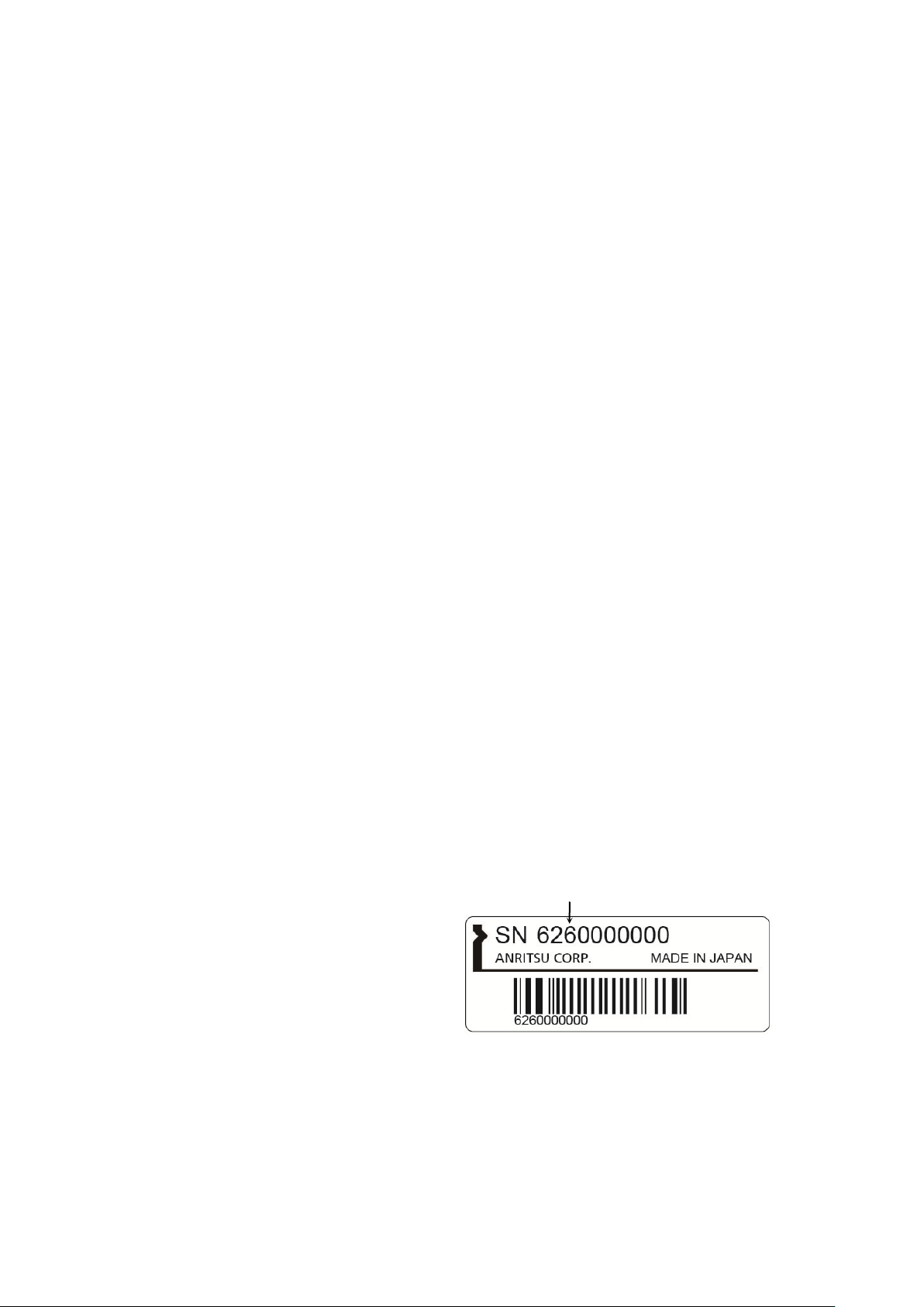
Serial number
If the third digit of the serial number is "7", the product
complies with Directive 2011/65/EU as amended by (EU)
2015/863.
(Pb,Cd,Cr6+,Hg,PBB,PBDE,DEHP,BBP,DBP,DIBP)
If the third digit of the serial number is "6", the product
complies with Directive 2011
(Pb,Cd,Cr6+,Hg,PBB,PBDE)
Third digit
B: The equipment shall continue to operate as intended after the
test. No degradation of performance or loss of function is
allowed below a performance level specified by the
manufacturer, when the equipment is used as intended.
The performance level may be replaced by a permissible loss of
performance. During the test, degradation of performance is
however allowed. No change of actual operating state or stored
data is allowed. If the minimum performance level or the
permissible performance loss is not specified by the
manufacturer, either of these may be derived from the product
description and documentation and what the user may
reasonably expect from the equipment if used as intended.
C: Temporary loss of function is allowed, provided the function is
self-recoverable or can be restored by the operation of the
controls.
Harmonic current emissions:
EN 61000-3-2: 2014 (Class A equipment)
No limits apply to this equipment with an active input
power under 75 W.
LVD: EN 61010-1: 2010 (Pollution Degree 2)
•
RoHS: EN IEC 63000: 2018 (Category 9)
•
xvi
/65/EU.
Page 17

4. Contact
Name: Anritsu GmbH
Address, city: Nemetschek Haus, Konrad-Zuse-Platz 1
81829 München,
Country: Germany
Name: ANRITSU EMEA Ltd.
Address, city: 200 Capability Green, Luton
Bedfordshire, LU1 3LU
Country: United Kingdom
xvii
Page 18

RCM Conformity Marking
Anritsu affixes the RCM mark on the following product(s) in accordance with
the regulation to indicate that they conform to the EMC framework of
Australia/New Zealand.
RCM marking
1. Product Model
Model: MP1900A Signal Quality Analyzer-R
2. Applied Standards
EMC: Emission: EN 61326-1: 2013 (Class A equipment)
xviii
Page 19

About Eco label
The label shown on the left is attached to Anritsu products meeting our
environmental standards.
Details about this label and the environmental standards are available
on the Anritsu website at https://www.anritsu.com
xix
Page 20

xx
Page 21
About This Manual
Configuration of Signal Quality Analyzer-R Series Operation
Describes the basic operations, panel details, and maintenance of the MP1900A, as
well as the steps from module installation to the start of use.
indicates this document.
Describes the panel details, how to operate, performance test, maintenance, and
troubleshooting of the
Module Operation Manual
Operation Manual
Describes the panel details, how to operate, performance test, maintenance, and
troubleshooting of the MU181000A
Describes the panel details, how to operate, performance test and maintenance of the
MU181500B.
Describes the panel details, how to operate, performance test, maintenance, and
Operation Manual
Describes the panel details, performance test, maintenance, and troubleshooting of
Describes the panel details, performance test, maintenance, and troubleshooting of
the
A testing system combining an MP1900A Signal Quality Analyzer-R,
module(s), and control software is called the Signal Quality Analyzer-R
Series. The operation manuals of the Signal Quality Analyzer-R Series
consist of separate documents for MP1900A, module(s), and control
software, as shown below.
MP1900A Signal Quality Analyzer-R Operation Manual
MU195020A 21G/32G bit/s SI PPG MU195040A 21G/32G bit/s SI ED
MU195050A Noise Generator Operation Manual
module to be installed on the MP1900A.
MU196020A PAM4 PPG MU196040A PAM4 ED MU196040B PAM4 ED
Operation Manual
MU196020A, MU196040A, and MU196040B.
MU181000A 12.5GHz Synthesizer MU181000B 12.5GHz 4 port Synthesizer
and MU181000B.
MU181500B Jitter Modulation Source Operation Manual
MU183020A 28G/32G bit/s PPG MU183021A 28G/32G bit/s 4ch PPG
the MU183020A and MU183021A.
MU183040A 28G/32G bit/s ED MU183041A 28G/32G bit/s 4ch ED
MU183040B 28G/32G bit/s High Sensitivity ED
MU183041B 28G/32G bit/s 4ch High Sensitivity ED Operation Manual
troubleshooting of the MU183040A, MU183041A, MU183040B, and MU183041B.
I
Page 22

Extended Application Operation Manual
MX183000A High-Speed Serial Data Test Software Operation Manual
Describes the setup and operating procedure of MX183000A.
Describes the operation of the extended application for the Signal Quality Analyzer-R
Series.
Configuration of Signal Quality Analyzer-R Series Operation (Cont’d)
indicates this document.
MX190000A Signal Quality Analyzer-R Control Software Operation Manual
Describes the operation of the software that controls the Signal Quality Analyzer-R
Series.
II
Page 23

5 4 3 2 1
Table of Contents
For Safety ............................................................ iii
About This Manual ................................................. I
Chapter 1 Overview ............................................ 1-1
1.1 Product Overview........................................................ 1-2
1.2 Product Configuration ................................................. 1-3
1.3 Specifications.............................................................. 1-6
Chapter 2 Panels and Connections .................. 2-1
2.1 Front Panel ................................................................. 2-2
2.2 Rear Panel .................................................................. 2-3
2.3 Side Panel .................................................................. 2-4
Chapter 3
3.1 Environmental Conditions of Installation Site ............... 3-2
3.2 Distance from Fan ....................................................... 3-3
3.3 Installing and Removing Modules ................................ 3-4
3.4 Power Connection ....................................................... 3-9
3.5 Measures Against EOS and ESD .............................. 3-11
3.6 Connecting with Peripheral Devices .......................... 3-12
3.7 Connecting Network .................................................. 3-14
3.8 Windows Security Measures ..................................... 3-15
Preparation Before Use.................... 3-1
6
7
8
Chapter 4 Start/Stop Procedures...................... 4-1
4.1 Start Procedure ........................................................... 4-2
4.2 Stop Procedure ........................................................... 4-3
III
Page 24

Chapter 5 Remote Control ................................. 5-1
5.1 Remote Interface Settings ........................................... 5-2
5.2 Using Ethernet ............................................................ 5-5
5.3 Using GPIB ................................................................. 5-8
Chapter 6 Installing MX190000A ....................... 6-1
6.1 Installing MX190000A ................................................. 6-2
Chapter 7 Troubleshooting ............................... 7-1
7.1 Problems upon Power-on ............................................ 7-2
7.2 Problem upon Module Replacement............................ 7-3
7.3 Software Problems ...................................................... 7-4
Chapter 8 Maintenance ...................................... 8-1
8.1 Daily Maintenance ...................................................... 8-2
8.2 Touch Panel Calibration .............................................. 8-3
8.3 System Recovery Function ......................................... 8-7
8.4 Caution on Storage ................................................... 8-27
8.5 Transportation........................................................... 8-28
8.6 Calibration ................................................................ 8-29
8.7 Disposal .................................................................... 8-30
IV.
Page 25

Overview
Chapter 1 Overview
This chapter provides an overview and the specifications of the MP1900A
Signal Quality Analyzer-R (hereinafter, referred to as “MP1900A”).
1.1
Product Overview........................................................ 1-2
1.2 Product Configuration ................................................. 1-3
1.2.1 Standard Configuration ................................... 1-3
1.2.2 Optional Accessories....................................... 1-5
1.3 Specifications.............................................................. 1-6
1
1-1
Page 26

Chapter 1 Overview
1.1 Product Overview
By installing various plug-in modules (hereinafter, referred to as
“module”), the MP1900A can support research, development and
production of module devices for the optical communication market or
high-speed bus interface such as PCI Express. The MP1900A is also
useful for research and development for the next-generation
communication market, including optical packet transmission.
Up to 8 modules can be installed into the MP1900A. The MP1900A is
equipped with touchpanel LCDs, keys and a rotary encoder for easy
operation. Remote control can also be performed by adding the GPIB or
LAN.
The latest information on modules that can be installed to the MP1900A
is available on the Anritsu website at https://www.anritsu.com.
1-2
Page 27
Overview
1.2 Product Configuration
Main unit
MP1900A
Signal Quality Analyzer-R
1
Accessories
G0342A
ESD Discharger
1
Power Cord, 3M
1
J1627A
GND connection cable
1
P0031A
USB Memory
1
Stores the latest set of the
MX183000A Software.
Z0306A
Wrist strap
1
MP1900A-110/210
Windows 10 Upgrade Retrofit
1
Hardware option
Enterprise 2019 LTS.
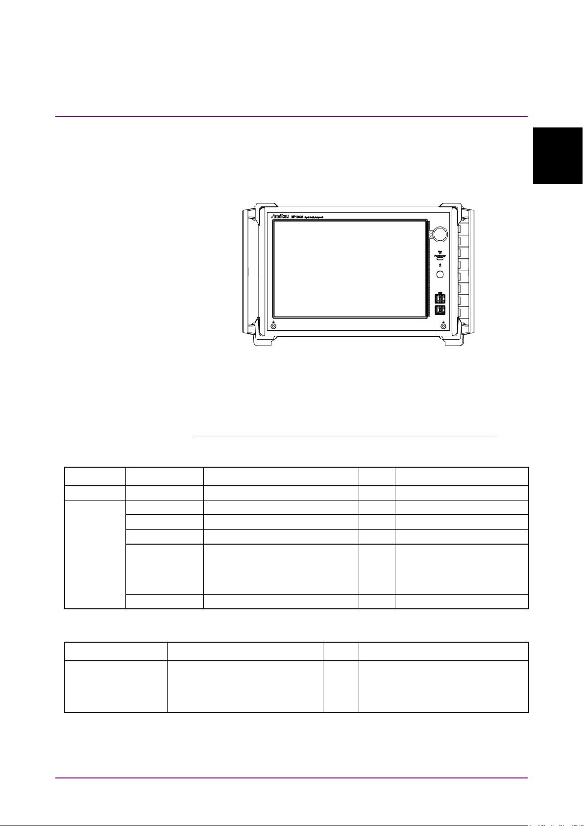
1.2.1 Standard Configuration
The MP1900A can operate alone, without an external control PC.
Figure 1.2.1-1 MP1900A appearance
1.2 Product Configuration
1
Table 1.2.1-1 shows the standard configuration of the MP1900A. The
latest information is available on the Anritsu website.
https://www.anritsu.com/en-us/test-measurement/products/mp1900a
Table 1.2.1-1 Standard Configuration
Item Model Product Name Q’ty Remarks
operation manuals, the
MX190000A Software and
Table 1.2.1-2 Option
Model Product Name Q’ty Remarks
Upgrade from Windows Embedded
Standard 7 to Windows 10 IoT
1-3
Page 28
MU195020A*
21G/32G bit/s SI PPG
MU195040A*
21G/32G bit/s SI ED
MU195050A*
Noise Generator
MU196020A*
PAM4 PPG
MU196040A*
PAM4 ED
MU196040B*
PAM4 ED
MU181000A
12.5GHz Synthesizer
MU181000B
12.5GHz 4port Synthesizer
MU181500B
Jitter Modulation Source
MU183020A*
28G/32G bit/s PPG
MU183021A*
28G/32G bit/s 4ch PPG
MU183040B*
28G/32G bit/s High Sensitivity ED
MU183041B*
28G/32G bit/s 4ch High Sensitivity ED
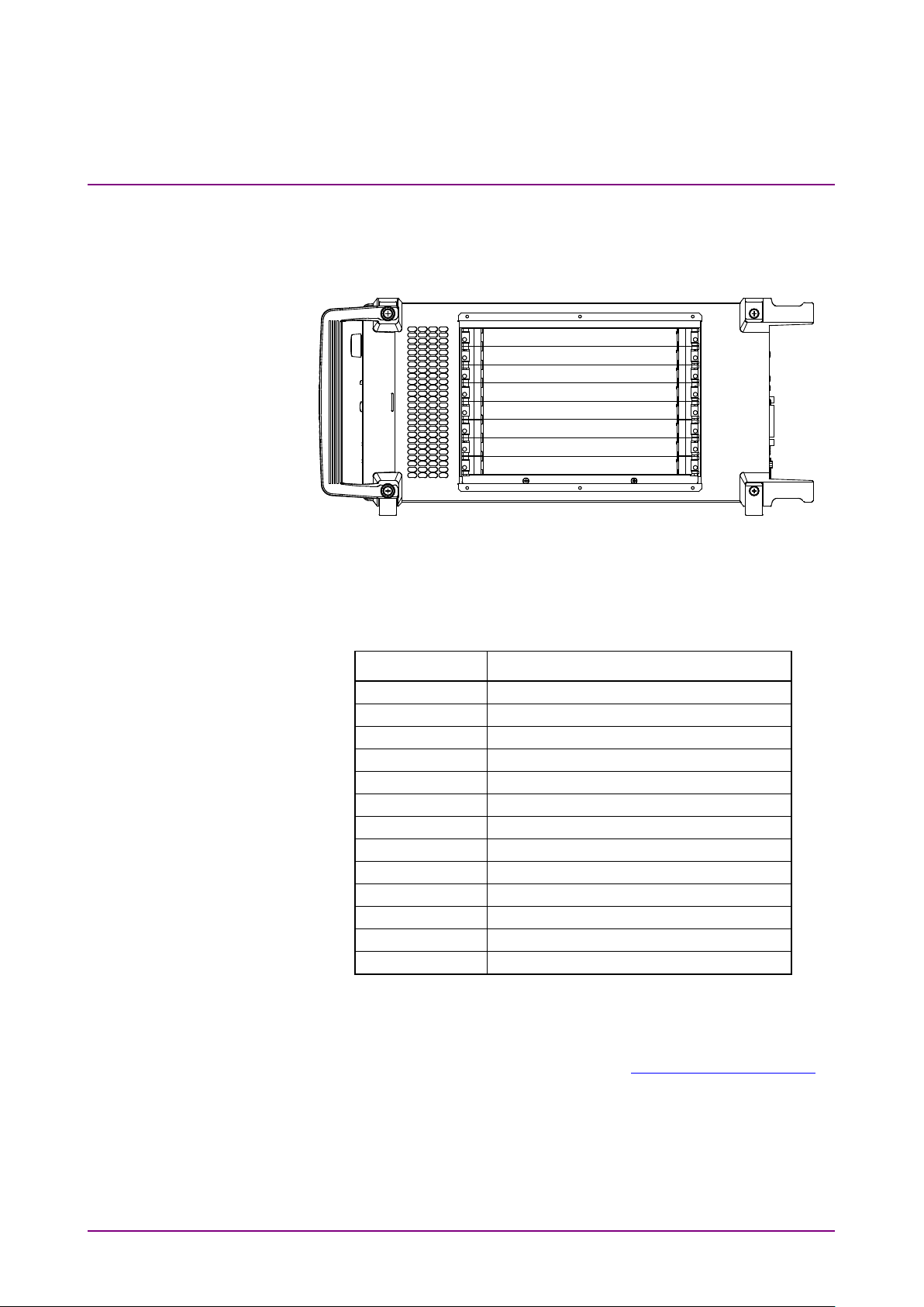
Chapter 1 Overview
■ Module insertion slots
The MP1900A is equipped with slots for installing up to 8 modules into
the side panel.
Figure 1.2.1-2 MP1900A Side Panel
The following modules are installable to the MP1900A.
Table 1.2.1-3 Installable Modules
Model Product Name
*: The module has restrictions on installation positions and a number
to install.
For the latest information of the modules that are installable to the
MP1900A, refer to the Anritsu web site (https://www.anritsu.com).
1-4
Page 29
Overview
1.2.2 Optional Accessories
B0736A
Front Cover (For MP1900A)
Necessary to put the
case.
B0737A
Carrying Case (For MP1900A)
B0738A
Rack Mount Kit (For MP1900A)
J0008
GPIB CABLE, 2.0 m
2 m
W3813AE
MX183000A Operation Manual
Printed version
W3911AE
MP1900A Operation Manual
Printed version
W3915AE
MU195020A/40A/50A Operation Manual
Printed version
W3976AE
MU196020A/40A/40B Operation Manual
Printed version
W3913AE
MX190000A Operation Manual
Printed version
Z0541A
USB Mouse
Z0917A
Shielded LAN Cable, 5m
Shielded LAN cable, 5 m
Z1746A
Stylus
Z1953A
Gigabit Ethernet Switch (5Port)
5 ports
B0576A
Blank Panel
Z1964A
Torque Wrench (Right Angle)
1.2 Product Configuration
Table 1.2.2-1 shows the options for the MP1900A. All options are sold
separately.
Table 1.2.2-1 Optional Accessories
Model Product Name Remarks
MP1900A into the carrying
1
1-5
Page 30
1
Functions
1.1
Input device, button
Resistance film touch panel, Rotary encoder, Function button,
Power button
1.2
LED
Power, Power Standby, Disk Access
1.3
LCD
12.1 inch WXGA (1280 × 800)
1.4
Ethernet
Rear panel 10/100/1000 Base-T RJ45 1 port
Reserved for future use )
1.5
External Display
VGA/HDMI
Rear panel D-Sub 15pin 1 port
Rear panel HDMI Type A 1 port
1.6
USB
Front panel USB Type A 4 ports
Rear panel USB Type A 2 ports
1.7
GPIB
Rear panel 1 port (For remote control)
1.8
Module slot
8 Slots (Slot1 to Slot8)
1.9
Functional earth terminal
Front panel 2 jacks
Rear panel 1 terminal
1.10
OS
Windows 10 IoT Enterprise 2019 LTSC
1.11
Internal storage device
SATA 2.5-inch SSD 1 Unit (tray loading)*1
1.12
Function
System and measurement sound output
Software-defined functions button
1.13
Remote interface
GPIB, Ethernet External (automatic switchover)
1.14
Internal reference clock
10 MHz ± 1 ppm (Accuracy at initial shipment)
2
Environmental performance
Power supply*2
AC 100 to 120 V, 200 to 240 V (automatic switching between
Power consumption
1350 VA
Operating temperature range
+5 to +40°C (without condensation)
Storage temperature range
–20 to +60°C (Recommended storage temperature range: +5 to
3
Mechanical measurements
Dimensions
222.5 mm (H) × 340 mm (W) × 451 mm (D) (Protrusions
excluded)
Mass
20 kg (excluding modules, blank panels, protective cover,
power cord)
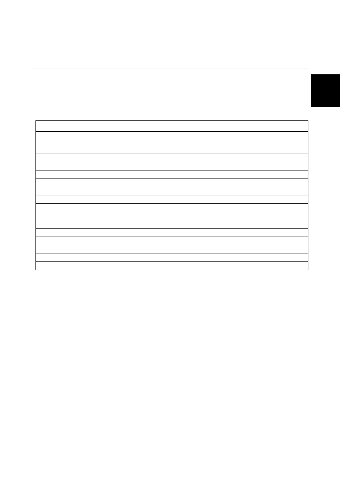
Chapter 1 Overview
1.3 Specifications
Table 1.3-1 MP1900A Specifications
No. Item Specifications
(External: For remote control)
Rear panel 10/100/1000 Base-T RJ45 1 port (Internal:
100 and 200 V systems), 50 to 60 Hz
+30°C)
≤
Removing and replacing the
*1:
warranty coverage.
*2: Operating voltage is –10 to +10% of rated voltage
The information on options and application parts for the MP1900A is
available on the Anritsu website at https://www.anritsu.com.
1-6.
by Customer is outside the scope of
SSD
Page 31

Panels and Connections
Chapter 2 Panels and Connections
This section describes panels and connections of the MP1900A
2.1
Front Panel ................................................................. 2-2
2.2 Rear Panel .................................................................. 2-3
2.3 Side Panel .................................................................. 2-4
2
2-1
Page 32

1
GND terminal
Connects to the wrist strap during operation, as a countermeasure
the MP1900A.
2
3
USB ports
Four USB ports are provided. Turn the connected peripherals off
before turning off the MP1900A.
4
Power switch
Turns the power to the MP1900A on/off. When this switch is turned
unplug the power cord to turn off the Standby LED entirely.
5
Function Key
Software-defined functionkey.
Signal Quality Analyzer-R Control Software Operation Manual
.
6
Storage device access
LED
Flashes when the storage device is being accessed.
7
Rotary encoder
Rotate to increase/decrease the numeric value.
Chapter 2 Panels and Connections
2.1 Front Panel
7
6
5
4
3
2 1
Figure 2.1-1 Front panel
Table 2.1-1 Front panel
No. Name Function
against static electricity. Be sure to use the wrist strap when using
off while the power cord is connected, the Standby LED above the
switch lights.
When the power is automatically turned off because of the
temperature abnormality, the Standby LED flashes. In this case,
For details, refer to Chapter 3 “Basic Operations” in the
MX190000A
2-2
Page 33

Panels and Connections
2.2 Rear Panel
1
GPIB connector
The GPIB connector. Connect a cable to the GPIB connector on the
it on may cause failure.
2
SSD
Slot to install a storage device. Open the cover when replacing the
storage device.
3
USB port
Two USB ports are provided. Turn off the connected peripherals
before turning off the MP1900A.
4
Ethernet connector
RJ45 for Internal, RJ45 for External
Refer to 5.2 “Using Ethernet” for detail
5
Inlet
Connect to a 100 to 120 Vac or to a 200 to 240 Vac power supply via
the 3-pin power cord.
6
VGA
VGA connector to display the screen to an external display device.
7
HDMI
HDMI connector to display the screen to an external display device.
8
Functional GND
GND terminal for ESD (Electrostatic Discharge)
Connect to Device under test with cables for common grounding.
2.2 Rear Panel
2
1
Figure 2.2-1 Rear panel
Table 2.2-1 Rear panel
No. Name Function
4 3
2
5 6 7 8
terminal
rear panel before turning on the MP1900A. Connection after turning
10/100/1000BASE are supported.
Internal: Reserved for future use.
External: Connectable to network
This is an interface for remote control.
2-3
Page 34

Chapter 2 Panels and Connections
2.3 Side Panel
Eight slots for installing modules are provided on the left side. See 3.3
“Installing and Removing Modules” for how to install/remove the module
to/from the slots.
Figure 2.3-1 Side panel
2-4.
Page 35

Chapter 3
This chapter describes preparations required before starting
measurements.
3.1
Environmental Conditions of Installation Site ............... 3-2
3.2 Distance from Fan ........................................................ 3-3
3.3 Installing and Removing Modules ................................. 3-4
3.3.1 Installing modules ............................................. 3-4
3.3.2 Removing modules ........................................... 3-7
3.4 Power Connection ........................................................ 3-9
3.4.1 Power Requirements ........................................ 3-9
3.4.2 Connecting the Power Cord ............................. 3-9
3.5 Measures Against EOS and ESD ............................... 3-11
3.5.1 How to use the GND connection cable .......... 3-11
3.5.2 How to use the ESD Discharger ..................... 3-11
3.6 Connecting with Peripheral Devices ........................... 3-12
3.7 Connecting Network ................................................... 3-14
3.8 Windows Security Measures ...................................... 3-15
3.8.1 Activating Firewall ........................................... 3-16
3.8.2 Installing Windows Important Update
3.8.3 Using Antivirus Software ................................ 3-22
Preparation Before Use
Programs (Windows Update) ......................... 3-19
3
Preparation Before Use
3-1
Page 36

Chapter 3 Preparation Before Use
3.1 Environmental Conditions of Installation Site
The MP1900A operates in the temperature range from 5 to 40C. Avoid
using it under any of the following environment conditions which may
cause failure.
● Strong vibrations
● High humidity or dust
● Direct sunlight
● Chemically active gases
● Substantial temperature changes
Note:
Dew may form inside of the MP1900A if it is moved to a warm
location after operating for a long time in a cool location. In such a
case, be sure to wait until the MP1900A becomes completely dry
before turning on the power switch. Doing so with condensation
present may cause a short circuit and damage the MP1900A.
Install the MP1900A horizontally as shown in Figure 3.1-1.
Figure 3.1-1 Installation Orientation
CAUTION
If the MP1900A is not installed in a “good” direction as
above, a small shock may turn it over and harm the user.
3-2
Page 37

3.2 Distance from Fan
A cooling fan is provided at the rear of the MP1900A. Install the
MP1900A at least 10 cm away from walls, peripheral devices, or the like
to prevent blockage of ventilation. Insufficient ventilation may cause the
internal temperature to rise, resulting in failure.
3.2 Distance from Fan
Min 10 cm away
Min 10 cm away
Figure 3.2-1 Distance from fan
Min 10 cm away
3
Preparation Before Use
3-3
Page 38

Chapter 3 Preparation Before Use
3.3 Installing and Removing Modules
Slots from the module are Slot1, Slot2, Slot3, Slot4, Slot5, Slot6, Slot7,
Slot8 from the top.
3.3.1 Installing modules
1. Disconnect the power cord.
2. Fully insert a module, sliding along the grooves.
3. Check that the module ejectors are set facing out. Fit the hooks into
Figure 3.3-1 MP1900A modules
holes on the chassis.
Hooks
Ejector
Figure 3.3.1-1 Module hooks
3-4
4. Upon insertion, use a Phillips screwdriver to tighten the screws on
both the left and right sides of the module.
Page 39

3.3 Installing and Removing Modules
Screws
Figure 3.3.1-2 Module screws
CAUTION
● Be sure to check that the power cord of the MP1900A is
disconnected before installing the modules. Installing
modules with the power cord connected may result in
failure.
3
Preparation Before Use
● Take countermeasures against static electricity (ESD)
when installing modules. Failure to do so may result in
failure.
● Make sure to insert the module completely horizontally
into the groove (see the figure below). Failure to do so
may deform the metal spring on top of the modules.
Insertion direction
Groove
Correct: plug-in module horizontal to grooves
Incorrect: plug-in module not horizontal to grooves
Figure 3.3.1-3 Module insertion
● Do not touch any electric component mounting surface.
Doing so may damage the components.
3-5
Page 40

Chapter 3 Preparation Before Use
CAUTION
● Be careful not to catch your fingers when manipulating
the ejector. Doing so may cause injury.
● Tighten the left and right screws after inserting a
module. Failure to do so may cause malfunction or
failure of the module, or allow it to drop out when
transported.
● Attach a blank panel to every slot where no module is
installed. Not attaching blank panels may result in
failure due to air currents or internal temperature rise.
3-6
Page 41

3.3.2 Removing modules
1. Disconnect the power cord.
2. Loosen the left and right screws on the module to be removed.
3. Press the red ejector lock buttons on both sides of the module to
unlock the ejector.
3.3 Installing and Removing Modules
Screws
3
Preparation Before Use
Figure 3.3.2-1 Modules screws
4. Set the ejectors to the outside.
5. Hold the ejectors and gently pull out the module.
Figure 3.3.2-2 Modules ejectors
3-7
Page 42

Chapter 3 Preparation Before Use
CAUTION
● Be sure to check that the power cord of the MP1900A is
disconnected before pulling out the modules. Pulling
out modules with the power cord connected may result
in failure.
● Take countermeasures against static electricity (ESD)
when pulling out modules. Failure to do so may result in
failure.
● Make sure to pull out the module completely
horizontally from the grooves (see the figure below).
Failure to do so may deform the metal spring on top of
the modules.
Pullout direction
Grooves
Correct: plug-in module horizontal to grooves
Incorrect: plug-in module not horizontal to grooves
Figure 3.3.2-3 Module pullout
● Do not touch any electric component mounting surface.
Doing so may damage the components.
● Be careful not to catch your fingers when manipulating
the ejector. Doing so may cause injury.
● Be sure to loosen the left and right screws on the
module and to release the ejector lock before setting
the ejector outside. Failure to do so may damage the
ejector.
3-8
Page 43

3.4 Power Connection
This section describes the procedures for supplying power.
3.4.1 Power Requirements
For normal operation of the MP1900A, observe the power voltage range
described below.
3.4 Power Connection
Power source Voltage range Frequency
100 Vac system 100 to 120 V 50 to 60 Hz
200 Vac system 200 to 240 V 50 to 60 Hz
Changeover between 100 and 200 V systems is made automatically.
Supplying power exceeding the above range may result in
electrical shock, fire, failure, or malfunction.
3.4.2 Connecting the Power Cord
Insert the power plug into an outlet, and connect the other end to the
power inlet on the rear panel. To ensure that the MP1900A is grounded,
always use the supplied 3-pin power cord, and insert the plug into an
outlet with an GND terminal. When the power cord is connected, the
Standby LED is lit and the MP1900A enters the standby status.
3
Preparation Before Use
CAUTION
3-9
Page 44

Chapter 3 Preparation Before Use
WARNING
If the MP1900A is connected to an ungrounded outlet, there
is a risk of receiving a fatal electric shock. In addition, the
peripheral devices connected to the instrument may be
damaged.
Always connect the MP1900A to a properly grounded
outlet. Do not use the instrument with an extension cord or
transformer that does not have a ground wire.
Unless otherwise specified, the signal-connector ground
terminal, like an external conductor of the coaxial
connector, of the instrument is properly grounded when
connecting the power cord to a grounded outlet. Connect
the ground terminal of DUT to a ground having the same
potential before connecting with the instrument. Failure to
do so may result in an electric shock, fire, failure, or
malfunction.
CAUTION
If an emergency arises causing the MP1900A to fail or
malfunction, disconnect the MP1900A from the power
supply by disconnecting either end of the power cord.
When installing the MP1900A, arrange the power inlet and
outlet so that an operator may easily connect or
disconnect the power cord. Moreover, DO NOT fix the
power cord around the plug and the power inlet with a
holding clamp or similar device.
If the MP1900A is mounted in a rack, a power switch for the
rack or a circuit breaker may be used for power
disconnection.
It should be noted that, the power switch on the front panel
of the MP1900A is a standby switch, and cannot be used to
cut the main power.
The MP1900A has a storage device. Do not remove the
power cord during startup of the MP1900A, except for an
emergency.
3-10
Page 45

3.5 Measures Against EOS and ESD
3.5 Measures Against EOS and ESD
This section describes how to prevent MP1900A from being damaged by
electrical over-stress (EOS) or electrostatic discharge (ESD).
3.5.1 How to use the GND connection cable
There is a risk of damaging MP1900A due to EOS if MP1900A and other
peripheral equipment (including experimental circuits) are not connected
to the common ground.
When connecting MP1900A and other peripheral (including experimental
circuits), connect other peripheral equipment to the ground terminal of
MP1900A’s chassis with the GND connection cable before connecting the
I/O connectors.
MP1900A
3
Preparation Before Use
Figure 3.5.1-1 How to Use the GND Connection Cable
3.5.2 How to use the ESD Discharger
There is a risk of damaging MP1900A if the coaxial cable you connect to
MP1900A is charged electrostatically.
To prevent MP1900A from being damaged by ESD, remove electrostatic
charges from the cable by using the ESD Discharger before cabling the
connectors.
The ESD Discharger can be used with one of SMA connector (and its
compatible connector) and V connector (and its compatible connector).
Other
Peripheral
Equipment
Figure 3.5.2-1 How to Use the ESD Discharger
3-11
Page 46

Chapter 3 Preparation Before Use
3.6 Connecting with Peripheral Devices
1. USB mouse, keyboard and other USB devices
Connect a cable with a Type A connector to the USB port on the front
or rear panel. Turn off the connected devices before turning off the
MP1900A.
2 ports 4 ports
Figure 3.6-1 USB interface
2. The MP1900A has four USB ports on the front panel and two USB
ports on the rear panel as standard. Use the USB ports to connect
the USB mouse or a keyboard.
3. Ethernet
Connect the RJ modular plug of a 10 BASE-T, 100 BASE-TX or
1000BASE-TX cable to the RJ45 connector on the rear panel. Refer to
5.2 “Using Ethernet” for details.
4. External display
Before turning on the MP1900A, connect the display cable to the
HDMI or VGA connector on the rear panel. The external display can
be used when the MP1900A is turned on. Connecting after the
MP1900A has been turned on may cause failure. Turn off the display
before turning off the MP1900A.
3-12
Page 47

3.6 Connecting with Peripheral Devices
3
Preparation Before Use
VGA HDMI
Figure 3.6-2 Display interface
5. A D-SUB 15 pins connector and a HDMI Type A connector are
provided on MP1900A’s rear panel as a standard feature. When the
resolution is set to 1280 × 800 pixels, simultaneous display on the
external display and the built-in LCD of the MP1900A can be
performed.
6. GPIB
Connect a cable to the GPIB connector on the rear of the MP1900A
before turning on the MP1900A. Connecting after the MP1900A has
been turned on may cause failure. Refer to 5.3 “Using GPIB” for
details.
3-13
Page 48

Chapter 3 Preparation Before Use
3.7 Connecting Network
When connecting the MP1900A to a network, be sure to set the IP address
using Network Connections on Windows, so as not to conflict with the IP
address of any other device on the network. Consult your network
administrator for available IP address. Refer to 5.2 “Using Ethernet” for
the IP address setting procedure. Do not connect the MP1900A to a
network which has possibly been invaded by a virus.
3-14
Page 49

3.8 Windows Security Measures
MP1900A uses Windows Embedded Standard 7 (WES7) 64-bit version or
Windows 10 IoT Enterprise (Win10) 64-bit version. When connecting
MP1900A to a network, in addition to connecting to secure and
virus-protected networks, the following procedures are recommended in
order to add protection against malware (malicious software) and viruses.
● Activating firewall
● Installing Windows important update programs
● Using antivirus software
The security measure settings condition of this product can be confirmed
from the Control Panel of Windows.
When the OS is WES7
1. Click Start → Control Panel from the Windows menu bar hidden in
the lower part of the screen.
3.8 Windows Security Measures
3
Preparation Before Use
2. Click System and Security → Action Center.
3. Click Security, and confirm security measures settings condition.
When the OS is Win10
1. Click Start → Windows System → Control Panel from the Windows
menu bar hidden in the lower part of the screen.
2. With View by: Category, click System and Security → Security and
Maintenance.
3. Click Security, and confirm security measures settings condition.
Note:
Security warnings are not displayed by factory default.
CAUTION
When connecting MP1900A to the Internet or to an external
network, there is a possibility an unpredictable problem or
damage may occur. Anritsu Corporation does not
recompense for any damage caused by connecting
MP1900A to a network.
3-15
Page 50

Chapter 3 Preparation Before Use
3.8.1 Activating Firewall
It is recommended to turn On the Windows firewall on MP1900A.
When the OS is WES7
1. Click Start → Control Panel from the Windows menu bar hidden in
2. With View by: Category, click System and Security → Windows
Note:
3. Click Turn Windows Firewall on or off found in left side of Windows
the lower part of the screen.
Firewall to show Windows Firewall window.
Windows Firewall is On when MP1900A is shipped from factory.
The settings to allow external communications are already done so
that MP1900A is operated properly by remote-control, etc. Thus,
additional settings are unnecessary.
Firewall window.
3-16
Figure 3.8.1-1 Windows Firewall Window
Page 51

3.8 Windows Security Measures
4. Customize Settings window will be shown where Windows firewall
On/Off settings can be changed.
Use MP1900A with the following checkboxes Off (unchecked).
● Block all incoming connections, including those in the list of
allowed programs
● Notify me when Windows Firewall blocks a new program
3
Preparation Before Use
Figure 3.8.1-2 Customize Settings Window
When the OS is Win10
1. Click the Start icon to open the Start menu, and then click
Windows System → Control Panel in the W column of the application
list displayed.
2. With View by: Category, click System and Security → Windows
Defender Firewall to show Windows Defender Firewall window.
Note:
Windows firewall is On when MP1900A is shipped from factory.
3. Click Turn Windows Defender Firewall on or off found in the left side
of Windows Defender Firewall window.
Figure 3.8.1-3 Windows Defender Firewall Window
3-17
Page 52

Chapter 3 Preparation Before Use
4. Customize Settings window will be shown where Windows firewall
On/Off settings can be changed.
Use the MP1900A with the following checkboxes Off (unchecked).
● Block all incoming connections, including those in the list of
allowed programs
● Notify me when Windows Firewall blocks a new program
Figure 3.8.1-4 Customize Settings Window
3-18
Page 53

3.8 Windows Security Measures
3.8.2 Installing Windows Important Update Programs (Windows Update)
It is necessary to regularly check for important Windows update
programs and keep them up-to-date. However, since executing update
program downloads and installations will decrease the performance of
MP1900A, deactivate automatic updates for Windows Update. Instead, it
is recommended to check for new updates, execute downloads and
installations periodically when MP1900A is not in use for measurement.
When the OS is WES7
1. Click Start → Control Panel from the Windows menu bar hidden in
the lower part of the screen.
2. With View by: Category, click System and Security → Windows
Update to show Windows Update window.
3. To deactivate automatic updates, click Change settings found in left
side of Windows Update window.
3
Preparation Before Use
Figure 3.8.2-1 Windows Update Window
3-19
Page 54

Chapter 3 Preparation Before Use
4. Select Never check for updates (not recommended) in Important
updates, then click OK.
Figure 3.8.2-2 Change settings Window
5. To check for newly available update programs (manual update), click
Check for updates in Windows Update window.
Figure 3.8.2-3 Windows Update Window (manual update)
6. When a new update program is found, download and install following
the displayed instructions.
3-20
Page 55

3.8 Windows Security Measures
When the OS is Win10
1. Click the Start icon to open the Start menu, and then click
Settings icon.
2. Click Update & Security to show Windows Update window.
3. To turn off automatic updates, select Windows Update found in left
side of Windows Update window, and then click Advanced options.
3
Preparation Before Use
Figure 3.8.2-4 Windows Update Window
4. Advanced options window will be shown.
Confirm if Automatically download updates even over metered data
connections (charges may apply) is set to Off.
Figure 3.8.2-5 Advanced options Window
3-21
Page 56

Chapter 3 Preparation Before Use
5. To check for newly available update programs (manual update), click
Check for updates in Windows Update window.
Figure 3.8.2-6 Windows Update Window (manual update)
6. When a new update program is found, download and install following
the displayed instructions.
3.8.3 Using Antivirus Software
It is recommended to install antivirus software on MP1900A. However,
since the automatic updates for virus data library and the full scans run
in the background by the antivirus software will decrease the
performance of MP1900A, do not execute them. Instead, it is
recommended to run them periodically when MP1900A is not in use for
measurement.
The antivirus software that checked operation in MP1900A is shown
below.
● Trend Micro OfficeScan XG
● Norton Security Deluxe (confirmed by version 22.11.0.41)
Note:
Refer to the antivirus software operation manual for its installation
and operation procedures. Although it is confirmed that no negative
effects in the general usage of MP1900A are caused by using the
software mentioned above, there is no guarantee for different
software even if containing similar functions.
3-22.
Page 57

Start/Stop Procedures
Chapter 4 Start/Stop Procedures
This chapter describes the start and stop procedures of the application
software for using the MP1900A.
4.1
Start Procedure ........................................................... 4-2
4.2 Stop Procedure ........................................................... 4-3
4
4-1
Page 58

Standby LED
Inlet
Chapter 4 Start/Stop Procedures
4.1 Start Procedure
At non-standby status (when Standby LED is off)
(1) When the power cord is connected, the Standby LED is lit and the
MP1900A enters the standby status.
Figure 4.1-1 Front and rear panels
At standby status (when Standby LED is on)
(1) Turn on the power switch of the MP1900A.
The power lamp is lit and Windows starts.
(2) After starting Windows, the Application Selector screen is displayed.
Touch the icon of the application to be started. For details of the
Application Selector screen, refer to the
Analyzer-R Control Software Operation Manual
MX190000A Signal Quality
.
4-2
Figure 4.1-2 Application Selector screen
Page 59

Start/Stop Procedures
4.2 Stop Procedure
(1) Press and hold the power switch on the front panel. The Power lamp
goes off, and then the Standby LED lights up (enters standby
status).
The MP1900A has a storage device. Do not remove the
power cord during startup of the MP1900A, except for an
emergency
4.2 Stop Procedure
CAUTION
4
4-3
Page 60

Chapter 4 Start/Stop Procedures
4-4.
Page 61

Remote Control
Chapter 5 Remote Control
Remote control of the MP1900A can be performed via Ethernet or GPIB
interface. This chapter describes the remote control procedure.
5.1
Remote Interface Settings ............................................ 5-2
5.2 Using Ethernet .............................................................. 5-5
5.3 Using GPIB ................................................................... 5-8
5
5-1
Page 62

Chapter 5 Remote Control
5.1 Remote Interface Settings
To remote-control the MP1900A by using the remote interface, set the
remote interface from
MP1900A has started, and select
window.
Refer to
Operation Manual
MX190000A Signal Quality Analyzer-R Control Software
Remote Control. Start the application after the
for details of System Toolbar.
Remote Control on the General Settings
5-2
Figure 5.1-1 System Toolbar
Tap the Navigation Tab on the upper right corner of the screen to display
the System Toolbar. Then Touch
.
Page 63

5.1 Remote Interface Settings
Remote Control
[1]
[3]
[2]
[5]
[4]
Figure 5.1-2 General Settings Window
Next, touch Remote Control to display a dialog box for setting remote
control. Set TCP port number and GPIB address for the MP1900A.
Figure 5.1-3 Remote Control Dialog Box
5
5-3
Page 64

[1]
SCPI control TCP port
Set the TCP/IP socket port number to remote-control
Software functions as the TCP server.
[2]
GPIB Address
Set the GPIB address of the MP1900A used when GPIB
is selected for the active interface.
[3]
Defaults
Resets the settings to default. The default values are
GPIB Address: 1
[4]
Cancel
Close this dialog box.
[5]
OK
Save the setting and close this dialog box.
Chapter 5 Remote Control
No. Type Function/operation
Table 5.1-1 Remote Control setting
MP1900A via Ethernet interface.
Perform the settings according to the Control PC or
other external controller.
MX190000A Signal Quality Analyzer-R Control
shown below.
SCPI control TCP port: 5 001
Refer to
MX190000A Signal Quality Analyzer-R Control Software
Operation Manual
for details of remote control.
5-4
Page 65

Remote Control
5.2 Using Ethernet
Specify IP Address, Subnet Mask, and Gateway for the MP1900A.
Connect the controller to the IP Address displayed on the Remote Control
tab.
(1) Click the Show Desktop icon at the right bottom of the screen.
Windows desktop is displayed.
5.2 Using Ethernet
Figure 5.2-1 Show Desktop Icon
(2) Click the Settings icon (
(3) Click Network and Internet to change the IP address, subnet mask,
and gateway address. Click
Network Connection window.
Figure 5.2-2 Network Connection Window
(4) Right-click the Ethernet icon, and then click Properties.
(5) Click Internal Protocol Version 4 (TCP IPv4), and then click
Properties.
) on the Windows Start menu.
Change adapter options to display the
5
5-5
Page 66

IP address
192.168.1.101
Subnet mask
255.255.255.0
Default gateway
Blank (not set)
Chapter 5 Remote Control
(6) Set the items in the Internal Protocol Version 4 (TCP/IPv4)
Properties dialog box.
Figure 5.2-3 Internal Protocol Version 4
(TCP/IPv4) Properties dialog box
Notes:
● For the IP address of the remote interface, set the address other
than “192.168.1.xxx”. The “192.168.1.xxx” address is used for
the module address. If this address is set, the module may not
operate properly.
● Do not change settings of Ethernet 2 (Do Not Change). When
the settings are changed, the application is not started normally.
Set the following values if the settings are changed.
Table 5.2-1 Ethernet 2 (Do Not Change) Default Values
Item Setting
5-6
Page 67

5.2 Using Ethernet
Remote Control
Twisted pair cable
HUB
Refer to
Operation Manual
External connector installed on the rear panel to connect the 10
BASE-T/100 BASE-TX/1000 BASE-TX cable.
MX190000A Signal Quality Analyzer-R Control Software
for details such as setup restrictions. Use the
5
Figure 5.2-4 Ethernet Cable Connection
5-7
Page 68

GPIB cable
Chapter 5 Remote Control
5.3 Using GPIB
The GPIB is available using the set GPIB address (refer to 5.1, “Remote
Interface Settings”).
GPIB connector is located on the rear panel. Be sure to connect the GPIB
cable before turning on the MP1900A. Up to 15 devices, including the
controller, can be connected in one GPIB system. Note that the cable
length is limited, as shown below.
● Total cable length: ≤20 m
● Cable length between devices: ≤4 m
Figure 5.3-1 GPIB Cable Connection
5-8
Page 69

Remote Control
(a) Daisy Chain
(b) Star
(c) Loop
Connect cables without forming loops.
5.3 Using GPIB
Figure 5.3-2 GPIB Cable Connection Methods
5
5-9
Page 70

Chapter 5 Remote Control
5-10.
Page 71

Installing MX190000A
Chapter 6 Installing MX190000A
This chapter describes how to install the MX190000A Signal Quality
Analyzer-R Control Software (hereinafter, referred to as “MX190000A”),
when reinstalling or upgrading MX190000A is required.
6.1
Installing MX190000A ................................................. 6-2
6
6-1
Page 72

Chapter 6 Installing MX190000A
6.1 Installing MX190000A
The MP1900A comes with MX190000A. When reinstalling or upgrading
MX190000A is required, follow the installation procedure described
below.
To re -install the MX190000A, use the USB flash drive supplied with the
MP1900A. If the MX190000A is updated, the firmware of the MP1900A
and each module should also be updated.
(1) Insert the USB flash drive into the MP1900A to copy the files to the
storage device. Files to be copied are stored in the following folder as
follows:
\Installer\MX190000A_VER_x_xx_xx.exe
x_xx_xx above indicates the software version.
(2) Execute “MX190000A_VER_x_xx_xx.exe” to start installation.
When overwriting a version of MX190000A that has already been
installed in the MP1900A (e.g., when upgrading the version), a
message dialog box “Reinstall all program features installed by the
previous setup.” is displayed. Touc h
In this event, Steps 4 (this step) to 8 are omitted. Proceed with Step
9.
(3) The installer starts. Touch
Next.
Yes to continue the installation.
6-2
Page 73

6.1 Installing MX190000A
Installing MX190000A
(4) Enter a user name, a company name, and the serial number into the
respective textbox, and then touch Next.
For the serial number, enter the 10-digit serial number of the
MP1900A that is to be controlled by MX190000A.
(5) The error message shown below will be displayed if an incorrect
serial number is entered and
error message, and then enter the correct serial number.
Next is touched. Touch OK to close the
6
6-3
Page 74

Chapter 6 Installing MX190000A
(6) Select MP1900A in the Setup Type and touch Next. When installing
the application to a PC, select External PC. Refer to
MX190000A
Signal Quality Analyzer-R Control Software Operation Manual
details.
for
(7) When installation is ready (the following window is displayed), touch
Install to start installation.
6-4
Page 75

6.1 Installing MX190000A
Installing MX190000A
(8) The following window is displayed when the installation completes
normally. Touch Finish to end the installation procedure.
(9) Be sure to check the software version of the MP1900A after
installing MX190000A. If the firmware version is not the latest,
necessary files must be downloaded. Refer to
Quality Analyzer-R Control Software Operation Manual
on how to check the version and how to upgrade the software.
MX190000A Signal
for details
6
6-5
Page 76

Chapter 6 Installing MX190000A
6-6.
Page 77

Troubleshooting
Chapter 7 Troubleshooting
This chapter describes the procedures to check if a failure has occurred
during abnormal operation of the MP1900A.
7.1
Problems upon Power-on ............................................ 7-2
7.2 Problem upon Module Replacement............................ 7-3
7.3 Software Problems ...................................................... 7-4
7
7-1
Page 78

The MP1900A
Is the power cord loose?
Fully connect the cable.
Is the Standby LED is
If the power cord is removed and inserted during
turned on by pressing the power switch on the front
Check if the power is being supplied to the power
version.
Is the MP1900A powered
abnormality?
When the power is automatically turned off because
off the Standby LED entirely.
Chapter 7 Troubleshooting
7.1 Problems upon Power-on
Table 7.1-1 Remedies for problems upon power-on
Symptom Location to Check Remedy
cannot be turned
on.
turned on?
startup of the MP1900A, the MP1900A may not be
panel. In this event, take either of these actions:
1. Remove the power cord, leave the Standby LED
turned off for at least 5 seconds, and then
reconnect the power cord.
2. Press and hold the power switch for at least 5
seconds, release the power switch, and then
press the power switch again.
cord. If the MP1900A cannot be turned on even
when the power is being supplied, the MP1900A
may have failed. Contact an Anritsu Service and
Sales office. Contact information can be found on
the last page of the printed version of this manual,
and is available in a separate file on the PDF
on after shutting it down
because of the temperature
of the temperature abnormality, the Standby LED
flashes. In this case, unplug the power cord to turn
7-2
Page 79

7.2 Problem upon Module Replacement
Troubleshooting
A module is not
Is the module installed
properly?
Install the module again by referring to 3.3
“Installing and Removing Modules”.
Are the appropriate
Confirm the MP1900A software version and the
version.
7.2 Problem upon Module Replacement
Table 7.2-1 Remedies for problems upon module replacement
Symptom Location to Check Remedy
recognized after
starting
application.
modules installed?
supported modules by visiting the MP1900A Series
Signal Quality Analyzers-R product information
page in the Anritsu web site
(https://www.anritsu.com).
If the appropriate modulus are not recognized, it
may have failed. Contact an Anritsu Service and
Sales office. Contact information can be found on
the last page of the printed version of this manual,
and is available in a separate file on the PDF
7
7-3
Page 80

The MX190000A
Is the MX190000A
Refer to Chapter 6 “Installing MX190000A” to
Windows does not
–
The storage device in MP1900A may have failed.
separate file on the PDF version.
The module is not
application.
Have the settings of
Ethernet 2 (Do Not
Change)
Set Ethernet 2 (Do Not Change) correctly by
Touch panel does
properly.
–
Calibrate the touch panel by referring to 8.2 “Touch
Chapter 7 Troubleshooting
7.3 Software Problems
Table 7.3-1 Remedies for software problems
Symptom Location to Check Remedy
application is not
installed.
start.
recognized after
starting the
not function
application registered in
the Windows start menu?
been changed?
If a problem cannot be solved using any of the items listed above,
perform initialization and check the items again. If the problem still
occurs, contact an Anritsu Service and Sales office. Contact information
can be found on the last page of the printed version of this manual, and
is available in a separate file on the PDF version.
re-install the MX190000A Control Software.
Contact an Anritsu Service and Sales office. Contact
information can be found on the last page of the
printed version of this manual, and is available in a
referring to 5.2, “Using Ethernet”.
Panel Calibration”.
7-4.
Page 81

Maintenance
Chapter 8 Maintenance
This section describes the maintenance of the MP1900A.
8.1
Daily Maintenance ...................................................... 8-2
8.2 Touch Panel Calibration .............................................. 8-3
8.2.1 When the operating system is WES7 ............... 8-3
8.2.2 When the operating system is Win10 ............... 8-5
8.3 System Recovery Function ......................................... 8-7
8.3.1 When the operating system is WES7 ............... 8-8
8.3.2 When the operating system is Win10 ............. 8-16
8.4 Caution on Storage ................................................... 8-27
8.5 Transportation........................................................... 8-28
8.6 Calibration ................................................................ 8-29
8.7 Disposal .................................................................... 8-30
8
8-1
Page 82

Chapter 8 Maintenance
8.1 Daily Maintenance
● Wipe off any external stains with a cloth damped with diluted mild
detergent.
● Vacuum away any accumulated dust or dirt with a vacuum cleaner.
● Tighten any loose parts fixed with screws, using the specified tools.
8-2
Page 83

Maintenance
8.2 Touch Panel Calibration
If the touch panel screen is not detected at the correct position, calibrate
the touch panel according to the following procedure. The procedure is
different, depending on the operating system installed on the MP1900A,
8.2.1 When the operating system is WES7
<Procedure>
1. Touch All Programs → DMC Touch Panel Configuration. (Figure
8.2.1-1
2. When the tool starts, touch Calibration.
3. Touch the center of + displayed at five locations on the screen with
your finger or stylus. (Figure 8.2.1-3)
4. Touch or click OK. The Calibration window is closed. (Figure 8.2.1-4)
) from the start menu of Windows.
8.2 Touch Panel Calibration
Figure 8.2.1-1 Touch Panel Calibration Procedure 1
8
Figure 8.2.1-2 Touch Panel Calibration Procedure 2
8-3
Page 84

Chapter 8 Maintenance
Figure 8.2.1-3 Touch Panel Calibration Procedure 3
8-4
Figure 8.2.1-4 Touch Panel Calibration Procedure 4
Page 85

Maintenance
8.2.2 When the operating system is Win10
<Procedure>
1. Touch Start ( ) → DMC → ExecuteCalibration.
2. When the following screen appears, touch on it twice with your
finger or stylus.
8.2 Touch Panel Calibration
3. Touch the center of each of the four markers displayed on the
screen with your finger or stylus.
8
8-5
Page 86

Chapter 8 Maintenance
4. When the calibration is completed, the following dialog box appears.
Touch or click
OK. The Calibration window is closed.
8-6
Page 87

Maintenance
8.3 System Recovery Function
The MP1900A has system recovery function to restore data on the hard
disk to the factory shipment status. The procedure to use this function is
different, depending on the operating system installed on the MP1900A,
These function can be used in the event of system instability.
Fully understand the following and back up all necessary
data before performing a system recovery.
● Executing system recovery restores the original
Windows factory settings, and reverts the data stored on
the C drive to the original factory state. All data such as
applications and updates subsequently added,
measurement conditions saved, measurement results,
and screen captures will therefore be deleted.
8.3 System Recovery Function
CAUTION
● Data deleted by these functions cannot be restored.
● The MX190000A must be re-installed if system recovery
is performed. Before performing system recovery,
prepare the MX190000A software installer for the version
you are using.
● Executing a system recovery disables the activated
MX183000A license. To hold these licenses, recover the
system according to the recovery procedure on the
following pages. The recovery procedure varies
depending on the version of Windows OS.
If the system is recovered in an inappropriate procedure,
the license keys are revoked and no longer available.
Please note that once disabled, the license key cannot
be used anymore. In case you have disabled the license
key, contact an Anritsu Service and Sales office. Contact
information can be found on the last page of the printed
version of this manual, and is available in a separate file
on the PDF version.
8
8-7
Page 88

Chapter 8 Maintenance
8.3.1 When the operating system is WES7
Note:
If both of the following conditions apply, be sure to preserve the
licenses temporarily before system recovery according to 2.4
“License Key Activation” in the
Data Test Software Operation Manual
● You are using the MX183000A of version earlier than 3.07.00.
● The MX183000A license has been activated.
If the operating system and the MX183000A you are using are
WES7 and version earlier than 3.07.00 respectively, , the
MX183000A licenses are cleared by a system recovery unless the
licenses are preserved temporarily in advance. In this case, contact
an Anritsu Service and Sales office. Contact information can be
found on the last page of the printed version and in a separate file
of the PDF version of this manual.
MX183000A High-Speed Serial
.
If the operating system and the MX183000A you are using are
WES7 and 3.07.00 or later version respectively, you do not need to
temporarily preserve the licenses because the MX183000A is newly
equipped with a function that automatically restores the
MX183000A licenses after a system recovery. To keep the
MX183000A licenses activated after a system recovery, run a
system recovery according to the following procedure:
8-8
Page 89

8.3 System Recovery Function
Maintenance
<Procedure>
1. Disconnect the MP1900A from the network if connected.
2. Connect the keyboard and mouse to the mainframe, and then turn
the MP1900A power On.
3. Press the F8 key on the keyboard. The following screen will appear.
4. Use the keyboard cursor keys to select Repair Your Computer, and
then press
5. Click Next.
Enter
.
8
8-9
Page 90

Chapter 8 Maintenance
6. Click OK. Leave the Password box blank.
7. Click Reinstall Windows.
8-10
Page 91

8.3 System Recovery Function
Maintenance
8. Click Yes.
9. The Recovery Processing window of Windows is displayed. The
recovery processing requires 10 to 30 minutes. The Recovery dialog
box is displayed after restarting MP1900A several times.
Click
Restore my files.
8
8-11
Page 92

Chapter 8 Maintenance
10. Click Cancel.
11. Install the MX190000A according to 2.1.1 “Installing” of the
MX190000A Signal Quality Analyzer-R Control Software Operation
Manual
12. Install the MX183000A High-Speed Serial Data Test Software
according to 2.3 “Installation/Uninstallation” of the
High-Speed Serial Data Test Software Operation Manual
13. Double-click the Do First icon on the desktop.
.
MX183000A
.
8-12
Page 93

8.3 System Recovery Function
Maintenance
14. The batch processing is executed.
15. After 10 minutes have passed, the screen to calibrate the touch
panel is displayed.
Touch the center of
with your finger or stylus.
displayed at the five locations in the screen
8
8-13
Page 94

Chapter 8 Maintenance
16. When the calibration is finished, the following screen is displayed.
If the calibration failed, touch or click
If the calibration succeeded, touch or click OK.
Then, the calibration screen is closed.
Cancel.
17. [Retry calibration again?(Y/N)] is shown in the command prompt.
If the calibration failed, press y or Y and press
keyboard. As the calibration screen is shown, retry the calibration.
If the calibration succeeded, press n or N and press
keyboard. Then, the MP1900A will automatically reboot.
Enter
on the
Enter
on the
8-14
Page 95

8.3 System Recovery Function
Maintenance
Checking operation
Check the operation using the following procedure after recovering the
system.
1. Touch All Programs → MX190000A → MX190000A from the start
menu of Windows.
Confirm that the following Application Selector screen is displayed.
2. Touch All Programs → MX183000A → High Speed Serial Data Test
Software from the Windows start menu.
Confirm that the following Selector window is displayed.
8
3. Activate the license that was moved to another PC before the system
recovery. For details, refer to 2.4 “License Key Activation” in the
MX183000A High-Speed Serial Data Test Software Operation
Manual
When using the MX183000A version
license is
.
3.07.xx or later, check that the
Active here.
8-15
Page 96

Chapter 8 Maintenance
8.3.2 When the operating system is Win10
Note:
If the MX183000A license is active, be sure to perform the
following procedure before performing system recovery.
If the system recovery is performed without performing the
procedure, the MX183000A license will be cleared. In that case,
contact an Anritsu Service and Sales office described in this
manual (at the end of the printed manual or in a separate file of
the electronic manual) "
<Procedure>
1. In the C:\Anritsu\MX183000A\Tools folder on the MP1900A,
double-click the MX183000_LicenseTools.exe file, and you will see
the following screen.
2.
Click Backup. Specify an external storage medium, for example the
USB flash drive that came with the MX183000A as a standard
accessory, and save a backup file to it. Check that the
MX183000A_opt file is saved to the specified external storage
medium.
3. Disconnect the MP1900A from the network if connected.
4. Connect the keyboard and mouse to the mainframe, and then turn
the MP1900A power On.
8-16
Page 97

8.3 System Recovery Function
Maintenance
5. Press the F8 key on the keyboard. The following screen will appear.
6. Use the keyboard cursor keys to select Repair Your Computer, and
then press
Enter
.
7. Click Troubleshoot.
8
8-17
Page 98

Chapter 8 Maintenance
8. Click Advanced option.
9. Click System Image Recovery.
8-18
Page 99

Maintenance
10. Click Anritsu_User.
8.3 System Recovery Function
11. When you are prompted to enter a password, enter “Anritsu_User”,
and then click
Continue.
8
8-19
Page 100

Chapter 8 Maintenance
12. Select Use the latest available system image (recommended), and
click
Next.
13. Click Next without any changes.
8-20
 Loading...