


MG3641A/MG3642A
Synthesized Signal Generator
Operation Manual
13th Edition
For safety and warning information, please read this
manual before attempting to use the equipment.
Keep this manual with the equipment.
ANRITSU CORPORATION
Document No.: M-W1137AE-13.0
Safety Symbols
To prevent the risk of personal injury or loss related to equipment malfunction, Anritsu Corporation uses the following
safety symbols to indicate safety-related information. Ensure that you clearly understand the meanings of the
symbols BEFORE using the equipment. Some or all of the following symbols may be used on all Anritsu
equipment. In addition, there may be other labels attached to products that are not shown in the diagrams in this
manual.
Symbols used in manual
DANGER
WARNING
CAUTION
This indicates a very dangerous procedure that could result in serious injury or
death if not performed properly.
This indicates a hazardous procedure that could result in serious injury or death if
not performed properly.
This indicates a hazardous procedure or danger that could result in light-to-severe
injury, or loss related to equipment malfunction, if proper precautions are not taken.
Safety Symbols Used on Equipment and in Manual
The following safety symbols are used inside or on the equipment near operation locations to provide information
about safety items and operation precautions. Ensure that you clearly understand the meanings of the symbols
and take the necessary precautions BEFORE using the equipment.
This indicates a prohibited operation. The prohibited operation is indicated
symbolically in or near the barred circle.
This indicates an obligatory safety precaution. The obligatory operation is
indicated symbolically in or near the circle.
This indicates a warning or caution. The contents are indicated symbolically in or
near the triangle.
This indicates a note. The contents are described in the box.
These indicate that the marked part should be recycled.
MG3641A/MG3642A
Synthesized Signal Generator
Operation Manual
10 March 1997 (First Edition)
7 December 2007 (13th Edition)
Copyright © 1997-2007, ANRITSU CORPORATION.
All rights reserved. No part of this manual may be reproduced without the prior written permission of the
publisher.
The contents of this manual may be changed without prior notice.
Printed in Japan
ii
For Safety
WARNING
1. ALWAYS refer to the operation manual when working near locations
at which the alert mark shown on the left is attached. If the advice in
the operation manual is not followed there is a risk of personal injury
or reduced equipment performance. The alert mark shown on the
left may also be used with other marks and descriptions to indicate
other dangers.
2. IEC 61010 Standard
The IEC 61010 standard specifies four categories to ensure that an
instrument is used only at locations where it is safe to make
measurements. This instrument is designed for measurement
category I (CAT I). DO NOT use this instrument at locations
specified as category II, III, or IV as defined below.
Measurement category I (CAT I):
Secondary circuits of a device that is not directly connected to a
power outlet.
Measurement category II (CAT II):
Primary circuits of a device that is directly connected to a power outlet,
e.g., portable tools or home appliance.
Measurement category III (CAT III):
Primary circuits of a device (fixed equipment) to which power is
supplied directly from the distribution panel, and circuits running from
the distribution panel to power outlet.
Measurement category IV (CAT IV):
Building service-line entrance circuits, and circuits running from the
service-line entrance to the meter or primary circuit breaker
(distribution panel).
iii
For Safety
WARNING
Electric Shock
Repair
Calibration
3. To ensure that the instrument is earthed, always use the supplied 3-
pin power cord, and insert the plug into an outlet with an earth
terminal. If power is supplied without earthing the equipment, there
is a risk of receiving a severe or fatal electric shock or causing
damage to the internal components.
4. This equipment cannot be repaired by the operator. DO NOT attempt
to remove the equipment covers or unit covers or to disassemble
internal components. Only qualified service personnel with a
knowledge of electrical fire and shock hazards should service this
equipment. There are high-voltage parts in this equipment presenting
a risk of severe injury or fatal electric shock to untrained personnel. In
addition, there is a risk of damage to precision components.
5. The performance-guarantee seal verifies the integrity of the equipment.
To ensure the continued integrity of the equipment, only Anritsu service
personnel, or service personnel of an Anritsu sales representative,
should break this seal to repair or calibrate the equipment. If the
performance-guarantee seal is broken by you or a third party, the
performance of the equipment cannot be guaranteed.
Falling Over
6. This equipment should always be positioned in the correct manner.
If the cabinet is turned on its side, etc., it will be unstable and may be
damaged if it falls over as a result of receiving a slight mechanical
shock.
Always set up the equipment in a position where the power switch
can be reached without difficulty.
iv
Fuse Replacement
Cleaning
For Safety
CAUTION
1. Always remove the mains power cable from the power outlet before
replacing blown fuses. There is a risk of electric shock if fuses are
replaced with the power cable connected. Always use new fuses of
the type and rating specified on the rear panel of the instrument.
There is a risk of fire if a fuse of a different rating is used.
T5A indicates a time-lag fuse.
2. Keep the power supply and cooling fan free of dust.
Clean the power inlet regularly. If dust accumulates around the
•
power pins, there is a risk of fire.
Keep the cooling fan clean so that the ventilation holes are not
•
obstructed. If the ventilation is obstructed, the cabinet may
overheat and catch fire.
3. Use two or more people to lift and move this equipment, or use a
trolley. There is a risk of back injury, if this equipment is lifted by one
person.
v

For Safety
CAUTION
Replacing Memory
Back-up Battery
Use in a residential
environment
This equipment uses a Poly-carbomonofluoride lithium battery to backup
the memory. This battery must be replaced by service personnel when
it has reached the end of its useful life; contact the Anritsu sales section
or your nearest representative.
Note: The battery used in this equipment has a maximum useful life of
7 years. It should be replaced before this period has elapsed.
This instrument is designed for an industrial environment.
In a residential environment this instrument may cause radio interference
in which case the user may be required to take adequate measures.
vi

Equipment Certificate
Anritsu Corporation certifies that this equipment was tested before
shipment using calibrated measuring instruments with direct traceability
to public testing organizations recognized by national research
laboratories, including the National Institute of Advanced Industrial
Science and Technology, and the National Institute of Information and
Communications Technology, and was found to meet the published
specifications.
Anritsu Warranty
Anritsu Corporation will repair this equipment free-of-charge if a
malfunction occurs within one year after shipment due to a manufacturing
fault, under the condition that this warranty is void when:
The fault is outside the scope of the warranty conditions described in
•
the operation manual.
The fault is due to mishandling, misuse, or unauthorized modification
•
or repair of the equipment by the customer.
The fault is due to severe usage clearly exceeding normal usage.
•
The fault is due to improper or insufficient maintenance by the
•
customer.
The fault is due to natural disaster including fire, flooding, earthquake,
•
etc.
The fault is due to use of non-specified peripheral equipment,
•
peripheral parts, consumables, etc.
The fault is due to use of a non-specified power supply or in a non-
•
specified installation location.
In addition, this warranty is valid only for the original equipment
purchaser. It is not transferable if the equipment is resold.
Anritsu Corporation shall assume no liability for injury or financial loss of
the customer due to the use of or a failure to be able to use this equipment.
Anritsu Corporation Contact
In the event that this equipment malfunctions, contact an Anritsu Service
and Sales office. Contact information can be found on the last page of
the printed version of this manual, and is available in a separate file on
the CD version.
vii

Notes On Export Management
r
This product and its manuals may require an Export License/Approval by
the Government of the product's country of origin for re-export from you
country.
Before re-exporting the product or manuals, please contact us to confirm
whether they are export-controlled items or not.
When you dispose of export-controlled items, the products/manuals need
to be broken/shredded so as not to be unlawfully used for military purpose.
viii

Crossed-out Wheeled Bin Symbol
Equipment marked with the Crossed-out Wheeled Bin Symbol complies
with council directive 2002/96/EC (the “WEEE Directive”) in European
Union.
For Products placed on the EU market after August 13, 2005, please
contact your local Anritsu representative at the end of the product's
useful life to arrange disposal in accordance with your initial contract and
the local law.
ix

CE Conformity Marking
Anritsu affixes the CE conformity marking on the following product(s) in
accordance with the Council Directive 93/68/EEC to indicate that they
conform to the EMC and LVD directive of the European Union (EU).
CE marking
1. Product Model
Model: MG3641A/MG3642A Synthesezed Signal
Generator
2. Applied Directive
EMC: Directive 2004/108/EC
LVD: Directive 2006/95/EC
3. Applied Standards
EMC:Emission: EN 61326-1: 2006 (Class A)
•
Immunity:EN 61326-1: 2006 (Table 2)
IEC 61000-4-2 (ESD) B
IEC 61000-4-3 (EMF) A
IEC 61000-4-4 (Burst) B
IEC 61000-4-5 (Surge) B
IEC 61000-4-6 (CRF) A
IEC 61000-4-8 (RPFMF) A
IEC 61000-4-11 (V dip/short) B, C
*: Performance Criteria
A: During testing, normal performance within the
specification limits.
B: During testing, temporary degradation, or loss of
function or performance which is self-recovering.
C: During testing, temporary degradation, or loss of
function or performance which requires operator
intervention or system reset occurs.
Performance Criteria*
x

Harmonic current emissions:
EN 61000-3-2: 2006 (Class A equipment)
LVD: EN 61010-1: 2001 (Pollution Degree 2)
•
4. Authorized representative
Name: Loic Metais
European Quality Manager
ANRITSU S.A. France
Address, city: 16/18 Avenue du Québec SILIC 720 Zone de
Courtaboeuf
91951 Les Ulis Cedex
Country: France
xi

C-tick Conformity Marking
Anritsu affixes the C-tick mark on the following product(s) in accordance
with the regulation to indicate that they conform to the EMC framework
of Australia/New Zealand.
C-tick marking
1. Product Model
Model: MG3641A/MG3642A Synthesezed Signal
Generator
2. Applied Standards
EMC:Emission: EN 61326-1: 2006 (Class A equipment)
xii

Power Line Fuse Protection
For safety, Anritsu products have either one or two fuses in the AC power
lines as requested by the customer when ordering.
Single fuse:
Double fuse:
Example 1: An example of the single fuse is shown below:
Example 2: An example of the double fuse is shown below:
A fuse is inserted in one of the AC power lines.
A fuse is inserted in each of the AC power lines.
Fuse Holder
Fuse Holders
xiii

xiv

TABLE OF CONTENTS
For Safety ................................................................................................................. iii
SECTION 1 GENERAL ............................................................................................. 1-1
1.1 Brief Description .............................................................................................................. 1-1
1.2 Operation Manual ............................................................................................................. 1-2
1.3 Composition of Devices ................................................................................................... 1-3
1.3.1 Standard Composition ...................................................................................... 1-3
1.3.2 Options ............................................................................................................. 1-4
1.4 Application Parts .............................................................................................................. 1-5
1.5 Specifications ................................................................................................................... 1-6
SECTION 2 PRECAUTION ....................................................................................... 2-1
2.1 Installation Precautions .................................................................................................... 2-1
2.1.1 Installation site environmental conditions ....................................................... 2-1
2.2 Safety Measures ................................................................................................................ 2-2
2.2.1 General power supply safety measures ............................................................ 2-2
2.2.2 Reverse power input to RF output connector ................................................... 2-2
2.3 Mounting the MG3641A/MG3642A in the Frame .......................................................... 2-3
2.4 Preparation Before Power-On .......................................................................................... 2-4
2.4.1 Connecting the Power Cord ............................................................................. 2-5
2.4.2 Fuse Replacement ............................................................................................ 2-6
SECTION 3 PANEL LAYOUT ................................................................................... 3-1
3.1 Panel Layout ..................................................................................................................... 3-1
3.1.1 Front panel layout ............................................................................................ 3-1
3.1.2 Rear panel layout ............................................................................................. 3-3
3.1.3 Panel layout diagram ........................................................................................ 3-4
SECTION 4 OPERATING INSTRUCTIONS ............................................................. 4-1
4.1 Turning Power On/Off ..................................................................................................... 4-1
4.1.1 Turning Power On ............................................................................................ 4-3
4.1.2 Turning Power Off ........................................................................................... 4-4
4.2 Explanation of Screens ..................................................................................................... 4-5
4.3 Initial Settings ................................................................................................................... 4-6
4.4 Setting the Frequency ....................................................................................................... 4-8
4.4.1 Setting the Frequency ....................................................................................... 4-8
4.4.2 Displaying the Frequency Relative Value ....................................................... 4-9
4.4.3 Frequency Offset ............................................................................................ 4-10
4.5 Setting the Output Level ................................................................................................. 4-11
4.5.1 Setting the Output Level ................................................................................ 4-11
4.5.2 Displaying the Output Level Relative Value ................................................. 4-12
4.5.3 Output Level Offset ....................................................................................... 4-13
I

4.5.4 Level Continuous Mode ................................................................................. 4-14
4.5.5 Switching the Output Signal On/Off .............................................................. 4-15
4.5.6 Special Functions Related to Level ................................................................ 4-16
4.6 Setting the Modulation ................................................................................................... 4-18
4.6.1 Outline of Modulation .................................................................................... 4-18
4.6.2 Setting the Modulation Function .................................................................... 4-19
4.6.3 Setting the Modulation Factor and Frequency Deviation .............................. 4-20
4.6.4 Setting Range of FM Frequency Deviation ................................................... 4-21
4.6.5 Polarity of Modulation Signal ........................................................................ 4-21
4.6.6 Pulse Modulation ........................................................................................... 4-22
4.7 Setting the Modulation Signal Source ............................................................................ 4-24
4.7.1 Internal Modulation Signal (Int1) .................................................................. 4-24
4.7.2 Internal Modulation Signals (Int2, Int3) ........................................................ 4-25
4.7.3 External Modulation Signals (Ext1, Ext2) ..................................................... 4-26
4.8 Setting the AF Output ..................................................................................................... 4-28
4.9 Memory Functions .......................................................................................................... 4-30
4.9.1 Outline of Memory Functions ........................................................................ 4-30
4.9.2 Storing in the Memory ................................................................................... 4-30
4.9.3 Recalling Memory Contents .......................................................................... 4-31
4.9.4 Clearing the Memory ..................................................................................... 4-33
4.9.5 Selecting the Memory Recall Mode ............................................................... 4-34
4.10 Sweep Functions ............................................................................................................. 4-35
4.10.1 Outline of Sweep Functions ........................................................................... 4-35
4.10.2 Setting and Executing the Sweep ................................................................... 4-36
4.10.3 Sweep Auxiliary Outputs ............................................................................... 4-39
4.11 Trigger Functions ........................................................................................................... 4-41
4.11.1 Outline of trigger function ............................................................................. 4-41
4.11.2 Registering the trigger program ..................................................................... 4-42
4.11.3 Executing the trigger program ....................................................................... 4-43
4.11.4 Checking the contents of the trigger program ................................................ 4-44
4.12 Miscellaneous Functions ................................................................................................ 4-45
4.12.1 Setting Display On/Off .................................................................................. 4-45
4.12.2 Setting Bell • Alarm On/Off ........................................................................... 4-46
4.12.3 Setting address and only mode of GPIB ........................................................ 4-47
4.12.4 Panel Lock ...................................................................................................... 4-48
4.13 Removing Reverse Power Protection (RPP) Circuit Operation ..................................... 4-49
4.14 Error Messages ............................................................................................................... 4-50
SECTION 5 MEASUREMENT .................................................................................. 5-1
5.1 Measurement of Sensitivity .............................................................................................. 5-1
5.1.1 Measuring 20 dB NQ sensitivity ...................................................................... 5-2
5.1.2 Measuring 12 dB SINAD sensitivity ............................................................... 5-3
II

5.2 Measuring the 1-signal Selectivity ................................................................................... 5-4
5.2.1 Measuring selectivity characteristics of the FM receiver in 20 dB
NQ method ....................................................................................................... 5-4
5.2.2 Measuring spurious response ........................................................................... 5-7
5.3 Measuring the 2-signal Sensitivity ................................................................................... 5-9
5.3.1 Measuring the sensitivity blocking of the FM receiver ................................... 5-9
5.3.2 Measuring the cross-modulation characteristics ............................................ 5-12
SECTION 6 GPIB...................................................................................................... 6-1
6.1 Outline of GPIB ................................................................................................................ 6-1
6.1.1 Overview .......................................................................................................... 6-1
6.1.2 GPIB functions ................................................................................................. 6-1
6.1.3 Setup example .................................................................................................. 6-2
6.1.4 Standard ........................................................................................................... 6-3
6.2 Device Message List ......................................................................................................... 6-4
6.2.1 Outline .............................................................................................................. 6-4
6.2.2 General Information On SCPI .......................................................................... 6-4
6.2.3 Command Structure ......................................................................................... 6-4
6.2.4 Writing Commands .......................................................................................... 6-5
6.2.5 Compounding Commands ................................................................................ 6-6
6.2.6 Parameter ......................................................................................................... 6-7
6.2.7 Unit ................................................................................................................... 6-7
6.2.8 Command Tree ................................................................................................. 6-8
6.3 Connecting the GPIB Cable ........................................................................................... 6-14
6.4 Device Message Format ................................................................................................. 6-15
6.4.1 Program message format ................................................................................ 6-15
6.4.2 Response message format .............................................................................. 6-18
6.5 Status Message ............................................................................................................... 6-20
6.5.1 Status register configuration .......................................................................... 6-20
6.5.2 IEEE488.2-based status register .................................................................... 6-21
6.5.3 SCPI standard status register .......................................................................... 6-22
6.5.4 Reading, writing, clearing, and resetting the status register .......................... 6-23
6.5.5 SCPI error messages ...................................................................................... 6-25
6.6 Initializing Device .......................................................................................................... 6-27
6.6.1 Bus initialization ............................................................................................ 6-27
6.6.2 Message initialization .................................................................................... 6-27
6.6.3 Device initialization ....................................................................................... 6-27
6.6.4 Device state at power-on ................................................................................ 6-27
6.7 Detailed Description of Commands ............................................................................... 6-28
6.7.1 Frequency subsystem ..................................................................................... 6-28
6.7.2 Output level subsystem .................................................................................. 6-32
6.7.3 AM subsystem ................................................................................................ 6-38
6.7.4 FM subsystem ................................................................................................ 6-39
6.7.5 PM subsystem ................................................................................................ 6-41
III

6.7.6 Modulation source subsystem ........................................................................ 6-42
6.7.7 MEMORY subsystem .................................................................................... 6-45
6.7.8 Display subsystem .......................................................................................... 6-47
6.7.9 System subsystem .......................................................................................... 6-48
6.7.10 Status subsystem ............................................................................................ 6-49
6.8 IEEE488.2 Common Command ..................................................................................... 6-51
6.9 Sample Program ............................................................................................................. 6-53
6.10 GPIB Command Interchange Function .......................................................................... 6-56
6.10.1 Outline ............................................................................................................ 6-56
6.10.2 Restrictions in MG3633Acommand interchange mode ................................. 6-57
6.10.3 Restrictions in MG3631A/32A command interchange mode ........................ 6-60
SECTION 7 PERFORMANCE TEST ........................................................................ 7-1
7.1 Performance Test Required .............................................................................................. 7-1
7.2 Performance Test Device List .......................................................................................... 7-2
7.3 Performance Test .............................................................................................................. 7-3
7.3.1 Output frequency .............................................................................................. 7-4
7.3.2 Output level frequency characteristics ............................................................. 7-5
7.3.3 Output level accuracy ....................................................................................... 7-6
7.3.4 FM deviation and FM distortion ...................................................................... 7-8
7.3.5 AM modulation factor and AM distortion ..................................................... 7-10
SECTION 8 CALIBRATION ...................................................................................... 8-1
8.1 Calibration Required ........................................................................................................ 8-1
8.2 Calibration Device List ..................................................................................................... 8-1
8.3 Calibration ........................................................................................................................ 8-2
SECTION 9 STORAGE AND TRANSPORTATION .................................................. 9-1
9.1 Daily Servicing and Preventive Maintenance .................................................................. 9-1
9.2 Storage Precautions .......................................................................................................... 9-1
9.2.1 Precautions before storage ............................................................................... 9-1
9.2.2 Recommended storage conditions ................................................................... 9-2
9.3 Repacking and Transportation .......................................................................................... 9-2
9.3.1 Repacking ......................................................................................................... 9-2
9.3.2 Transportation .................................................................................................. 9-2
APPENDIX A INITIAL FACTORY SETTINGS ............................................................. A-1
APPENDIX B FUNCTION-KEY TRANSITION ............................................................ B-1
APPENDIX C FRONT AND REAR PANEL LAYOUT ..................................................C-1
APPENDIX D INDEX ................................................................................................... D-1
APPENDIX E PERFORMANCE TEST RESULT SHEET ............................................ E-1
IV
.

SECTION 1 GENERAL
SECTION 1
GENERAL
1.1 Brief Description
The MG3641A/MG3642A is a synthesized signal generator capable of outputing highly accurate, highly pure signals
over a broad frequency range.
The extremely excellent spurious characteristics and leakage characteristics offer to make the signal generator most
suitable to evaluate sensitivity characteristics and interference characteristics, which comprise the basic performance
of radio equipment.
Meanwhile, the signal generator can also be used to test communication systems operating with a variety of modulation
methods, such as a pager system, since it provides diverse modulation functions and frequency modulation with good
carrier frequency stability.
Its output level can be corrected over the entire frequency range. Because the signal generator allows to select high
level outputs and high resolutions, it can also serve to test various high frequency components.
The generator displays its basic functions, such as frequency, output level, and memory addresses, on a 7-segment
display unit. For those functions which require to have many parameters set, such as modulation, sweep function,
etc., it adopts the multimenu display. Moreover, the generator boasts of an outstanding operability, since it comes
equipped with a dedicated rotary knob and step keys for setting output levels.
1-1

SECTION 1 GENERAL
1.2 Operation Manual
This operation manual contains 9 sections and 5 appendixes. The format and outline of each section is described
below.
Table 1-1
Section Title Contents
1 GENERAL
2 PRECAUTION
3 PANEL LAYOUT
4 OPERATING
INSTRUCTIONS
5 MEASUREMENT
6 GPIB
7 PERFORMANCE TEST
8 CALIBRATION
9 STORAGE AND
TRANSPORTATION
APPENDIX A INITIALSETTINGS
B FUNCTION KEY
TRANSITION
DIAGRAM
C FRONT AND REAR
PANEL LAYOUT
D INDEX
E PERFORMANCE
TEST RESULT
SHEET
Description of the MG3641A/MG3642A (standard configuration,
specifications), optional accessories and peripheral equipment, and outline of
operation manual.
Operations to be performed before powering-up the MG3641A/MG3642A
Layout, function and method of preparative operation of components such as
keys, connectors, knobs, and indicators on both the front and rear panels.
Details of manual operation (local operation) of the front and rear panels. (Except
for remote control by GPIB)
Explains how to measure the sensitivity and selectivity, giving typical
examples using the signal generator
Remote-control operational procedure and description of device messages
Description of the measuring unit and performance test required to test the
performance of this device
Description of the calibration as the preventive maintenance to prevent the
performance from reducing.
Daily maintenance, long period storage, re-packing and transportation
1-2

1.3 Composition of Devices
The composition of standard accessories to the MG3641A/MG3642A will be explained in this section.
1.3.1 Standard Composition
The table below shows the standard composition of devices for the MG3641A/MG3642A.
Table 1-2. Standard Composition of Devices
Item Model/Symbol Product Name Q'ty Remarks
Main unit MG3641A/
MG3642A
Accessories Power cord 1 Length: approx. 2.6 m
B0325 GPIB shield cap 1
F0013 Fuse 1
or
F0012
W1137AE Operation manual 1 English version
W1137BE Service manual 1 English version
Synthesized signal generator 1
Two of 5 A (T5 A 250 V) for 100 VAC system
or
Two of 3.15 A (T3.15 A 250 V), for 200 VAC
system
SECTION 1 GENERAL
1-3

SECTION 1 GENERAL
1.3.2 Options
The table below lists options for the MG3641A/MG3642A.
Table 1-3. Options
Option
No.
01 MG3641A/ Reference Crystal Oscillator
Model number/
Order number
MG3642A-01
Name
Frequency: 10 MHz
Aging rate: 5×10
Temperature caracteristics: ±5×10⁻⁹ (at 0 to 50°C)
11 MG3641A/ Pulse ON/OFF ratio: >80 dB
MG3642A-11
modulator
Rise time/fall time: <100 ns
Minimum pulse width: <500 ns
Pulse repetition frequency: DC to 1 MHz
Maximum delay time: <100 ns
Overshoot/ringing: <20 %
Video feed through: <20 %
Pulse modulation signal: External, BNC connector on
21 MG3641A/
MG3642A-21
AF synthesizer
Frequency : 0.01 Hz to 400 kHz (sine wave)
: 0.01 Hz to 50 kHz
Resolution : 0.01 Hz
Wave form: sine wave, triangular wave, square wave,
sawtooth wave
Frequency accuracy: Equal to the accuracy of the refere-
22
MG3641A/
FSK encoder
2-level FSK, 4-level FSK
MG3642A-22
–10
/day
the rear panel, 50 Ω/600 Ω,
TTL(Positive logic)
(triangular, square, sawtooth wave)
nce oscillator.
1-4
SECTION 1 GENERAL
1.4 Application Parts
The table below lists application parts for the MG3641A/MG3642A, which are all optional purchase items.
Table 1-4. Application Parts
Model/Symbol Product Name Remarks
J0576B Coaxial cord N-P•5D-2W•N-P, 1 m
J1027A Coaxial cord BNC-P•RG58A/U•BNC-P, 1 m
J0007 GPIB cable 408JE-101, 1 m
J0008 GPIB cable 408JE-102, 2 m
MP51A Pad Conversion from 75 Ω system to 50 Ω system
MP52A Pad Conversion from 50 Ω system to 75 Ω system
MA1612A Four-port junction pad 5 to 3000 MHz, 50 Ω
MP721 Fixed attenuator DC to 12.4 GHz, 3, 6, 10, 20, 30, 40, 50, 60 dB
1-5
SECTION 1 GENERAL
1.5 Specifications
Carrier Range 125 kHz to 1040 MHz: MG3641A
Frequency
Resolution 0.01 Hz
Accuracy Dependent on the accuracy of the reference oscillator.
Internal reference Frequency 10 MHz
oscillator
*1
External reference input 5/10 MHz, ±10 ppm, ≥0.7 Vp–p/50 Ω (AC coupling)
Buffer output 10 MHz, TTL level (DC coupling)
Switching time Response time from last command, till the preset frequency ±0.1 ppm
Output level Range –143 to +17 dBm (Permissible setting range: –143 to +23 dBm)
Unit dBm, dBµ, V, mV, µV
Resolution 0.01dB
Frequency response With reference to 0 dBm
Accuracy With pulse modulation off
Impedance 50 Ω, type N connector
Switching time Response time from last command, till the final level ±0.5 dB is
Special setting mode Level continuous mode:
*1 Available up to 5×10
*2 Only with Pulse Modulator(Opt. 11) installed
125 kHz to 2080 MHz: MG3642A
In the FM modulation,
Accuracy of reference frequency ±(0.3 % of FM deviation setting +5 Hz)
Aging rate ±5×10⁻⁹/day
Startup characteristics 1×10⁻⁷/10 min. (reference after 24-hour
operation)
Temperature stability ±3×10⁻⁸ (0 to 50°C)
BNC connector on the rear panel
BNC connector on the rear panel
is obtained, under external control:
<40 ms
(Switching between terminated-voltage display and open-voltage
display is possible for dBµ, V, mV and µV)
±0.5 dB
±1.0 dB (With pulse modulation on)
*2
±1 dB (≤+17 dBm, ≥–127 dBm)
±3 dB (<–127 dBm)
With pulse modulation on
*2
±1 dB (≤+12 dBm, ≥–127 dBm)
±3 dB (<–127 dBm)
VSWR: <1.5 (≤–3 dBm)
<2.5 (>–3 dBm)
obtained, under external control:
<50 ms (Normal mode)
<100 ms (Level safety mode)
<10 ms (continuous mode)
Level can be varied over a range of the set value ±10 dB, without
interruptions of the output
Level safety mode:
Level is narrowed to prevent spike-like signals from appearing when
the mechanical attenuator is working.
-10
/day with Reference Crystal Oscillator(Opt.01)
1-6
Specifications (continued)
SECTION 1 GENERAL
Output level
Interference radiation When measured with 50 Ω-terminated voltage using a two-loop
distortion
antenna of 25 mm in diameter at 25 mm away from the case:
<0.1 µV (At the output frequency)
<1 µV (Over the frequency range, at multimenu display OFF)
Signal Purity Spurious In CW mode and with reference to ≤+7 dBm:
Harmonics: <–30 dBc
Non-harmonics: <–100 dBc (≥15 kHz offset)
Those related to power: <–40 dBc (<15 kHz offset)
SSB phase noise In CW mode and with reference to 20 kHz offset:
<–140 dBc/Hz (≥10 MHz, <256 MHz)
<–136 dBc/Hz (≥256 MHz, <512 MHz)
<–130 dBc/Hz (≥512 MHz, ≤1040 MHz)
<–124 dBc/Hz (>1040 MHz, MG3642A)
Residual AM With reference to ≥500 kHz, CW mode, +7 dBm and in a 50 Hz to 15
kHz demodulation band:
<–80 dBc
Residual FM In CW mode and in a 300 Hz to 3 kHz demodulation band:
<4 Hzrms (≥10 MHz, <512 MHz)
<8 Hzrms (≥512 MHz, ≤1040 MHz)
<16 Hzrms (>1040 MHz, MG3642A)
In CW mode and in a 50 Hz to 15 kHz demodulation band:
<5 Hzrms (≥10 MHz, <512 MHz)
<10 Hzrms (≥512 MHz, ≤1040 MHz)
<20 Hzrms (>1040 MHz, MG3642A)
Amplitude Range 0 to 100 %
modulation
Resolution 0.1 %
Accuracy With reference to ≥0.4 MHz, ≤+7 dBm, AM≤90 %, Source=Int1 1
kHz, and in a 300 Hz to 3 kHz demodulation band:
±(5 % of set value +2 %)
Modulation frequency In ≤+7 dBm and ±1 dB Bandwidth:
response
Carrier frequency Lower limit frequency Upper limit frequency
≥
0.4 MHz, <0.5 MHz 2 kHz 1 kHz
≥
0.5 MHz, <2 MHz DC (Ext DC couple) 10 kHz 5 kHz
≥
2 MHz, <32 MHz 20 Hz (Ext AC couple) 20 kHz
≥
32 MHz, <64 MHz 50 kHz
≥
64 MHz 50 kHz
100 kHz (3 dB Bandwith)
AM = 30 % AM = 90 %
Distortion
With reference to ≥0.4 MHz, ≤+7 dBm, Source = Int1 1 kHz:
<–40 dB (AM = 30 %)
<–30 dB (AM = 90 %)
1-7

SECTION 1 GENERAL
Specifications (continued)
Amplitude Incidental FM With reference to ≥0.4 MHz, ≤+7 dBm, AM≤30 %, Source=Int1 1 kHz,
modulation
Modulation signal source Any one out of the internal modulation signal sources (Int1, Int2,
Modulation signal polarity Can be switched between positive and negative.
Frequency Range 0 to 125 Hz (≥125 kHz, <250 kHz)
modulation 0 to 250 Hz (≥250 kHz, <500 kHz)
Resolution 1 Hz (0 to 4.000 kHz deviation)
Accuracy With reference to ≥0.4 MHz, Source=Int1 1 kHz, and in a 300 Hz to
Modulation frequency In a ±1 dB bandwidth
response DC (Ext DC couple) or 20 Hz (Ext AC couple) to 20 kHz (≥0.4 MHz, <10 MHz)
Distortion With reference to ≥16 MHz:
Incidental AM With reference to ≥64 MHz, ≤+7 dBm, FM 100 kHz deviation,
External modulation group With reference to ≥10 MHz, Source=Ext DC coupling, and modulation
delay rate ≤100 kHz:
Modulation signal source Any one out of the internal modulation signal sources (Int1, Int2,
Modulation signal polarity Can be switched between positive and negative independently for
and in a 300 Hz to 3 kHz demodulation band:
<200 Hzpeak
Int3) and external modulation inputs (Ext1, Ext2) can be selected.
0 to 500 Hz (≥500 kHz, <1 MHz)
0 to 1 kHz (≥1 MHz, <2 MHz)
0 to 2 kHz (≥2 MHz, <4 MHz)
0 to 4 kHz (≥4 MHz, <8 MHz)
0 to 10 kHz (≥8 MHz, <16 MHz)
0 to 25.6 kHz (≥16 MHz, <32 MHz)
0 to 51.2 kHz (≥32 MHz, <64 MHz)
0 to 102 kHz (≥64 MHz, <128 MHz)
0 to 256 kHz (≥128 MHz, <256 MHz)
0 to 512 kHz (≥256 MHz, <512 MHz)
0 to 1024 kHz (≥512 MHz, ≤1040 MHz)
0 to 2048 kHz (>1040 MHz, MG3642A)
10 Hz (4.010 to 10.000 kHz deviation)
25 Hz (10.025 to 25.600 kHz deviation)
50 Hz (25.65 to 51.20 kHz deviation)
100 Hz (51.30 to 102.00 kHz deviation)
250 Hz (102.25 to 256.00 kHz deviation)
500 Hz (256.5 to 512.0 kHz deviation)
1 kHz (513 to 1024 kHz deviation)
1 kHz (1025 to 2048 kHz deviation, MG3642A)
3 kHz demodulation band:
±(5 % of set value +10 Hz) (≥0.4 MHz, <512 MHz)
±(5 % of set value +20 Hz) (≥512 MHz, ≤1040 MHz)
±(5 % of set value +40 Hz) (>1040 MHz, MG3642A)
DC (Ext DC couple) or 20 Hz (Ext AC couple) to 100 kHz (≥10 MHz)
–40 dB (FM=3.5 kHz deviation, and Source=Int1 1 kHz),
–45 dB (FM=22.5 kHz deviation, and Source=Int1 1 kHz)
Source=Int1 1 kHz, and in a 300 Hz to 3 kHz demodulation band:
<1 %peak
<30 µs
Int3) and external modulation inputs (Ext1, Ext2) can be selected for
each of FM1 and FM2.
FM1 and FM2.
1-8
SECTION 1 GENERAL
Specifications (continued)
Pulse See specifications of options.
modulation
Modulation Internal modulation (Int1) Frequency: 400 Hz/1 kHz (Switched over)
signal source
Internal modulation See specifications of options.
(Int2, Int3)
External modulation Optimum input level: Approx. 2 Vp–p
(Ext1, Ext2) Input impedance: 600 Ω, BNC connector on the front panel
AF Output Output signal source Any one out of the internal modulation signal sources (Int1, Int2,
Output level 0 to 4 Vp–p
Output level resolution 1 mVp–p
Output level accuracy In Source=Int1 1 kHz:
Impedance 600 Ω, BNC connector on the front panel
Simultaneous Simultaneous modulation, AM depth and FM deviation can be set
modulation independently for all combinations, except for a combination of AM
Sweep function Sweep parameter Frequency, Output level, and Memory
Sweep pattern Frequency sweep (Start/Stop): Liner (Stepsize specified, number
Sweep mode Auto, Single, Manual
Sweep time Setting range 1 ms to 600 s/point, Resolution 10 µs/point
Auxiliary outputs X-Output : BNC connector on the rear panel
Frequency accuracy: Equal to the accuracy of the reference oscillator.
Coupling: Switchable between AC/DC
Int3) and external modulation inputs (Ext1, Ext2) can be selected.
±(5% of set value + 2 mVp-p)
and pulse modulation.
of points specified)
Log (1 % specified)
Frequency sweep (Center/Span): Liner (Stepsize specified, number
of points specified)
Level sweep (Start/Stop): dB (Stepsize specified, number of points
specified)
Sweep in continuous mode (max. 20 dB width)
Level sweep (Center/Span): dB (Stepsize specified, number of points
specified)
Sweep in continuous mode (max. 20 dB width)
Memory sweep (Start/Stop)
(Actual sweep time depends on the sweep parameter switching times,
frequency, and output level.)
Staircase sawtooth wave worm
Start point of sweep: 0 V
Stop point of sweep: +10 V
Z-Output : BNC connector on the rear panel
TTL level
When sweeping: H-level
Blanking-Output : BNC connector on the rear panel
TTL level
When switched: L-level
Marker-Output : BNC connector on the rear panel
TTL level
When marker matches: H-level
1-9

SECTION 1 GENERAL
Specifications (continued)
Other functions Relative value display Carrier frequency and output level
Offset display Carrier frequency and output level
Memory 1000 panel setting conditions can be stored and recalled.
Recall mode: All panel settings, Frequency only, Frequency and Level.
Trigger function An external trigger signal (input from the BNC connector on the rear
panel, TTL level) can be used to execute a pre-programmed operation
sequence (except for operation of the power switch, Preset key, Local
key, and rotary knob).
Max. number of sequence steps of trigger program: 20 steps
Backup When switched on, the generator restores the same setting conditions
that existed immediately before it was last powered off.
However, the following are not restored:
• Data which was in the middle of entry
• Remote status
• Data which was in the middle of GPIB transfer
• Operating status of RPP
GPIB Can control all functions, except for pre-programmed operations
controlled by the trigger function, and operation of the power switch,
Local key, rotary knob, and knob resolution set keys.
Interface: SH1, AH1, T5, L3, TE0, SR1, RL1, PP0, DC1, DT1, C0,
E2
Reverse power Maximum reverse input 50 W (≤1040 MHz), 25 W (1040 to 2080 MHz, MG3642A only)
protection power ±50 Vac
General Power Voltage: *Vac (Up to max. 250 V)
Frequency: 47.5 to 63 Hz, 380 to 420 Hz
Capacity: 200 VAmax
Environmental performance Working temperature range: 0 to 50°C
Storage temperature range: –30 to 71°C
Conducted disturbance: EN 61326-1: 2006 (Class A)
Radiated disturbance: EN 61326-1: 2006 (Class A)
Harmonic Current Emission: EN 61000-3-2: 2006 (Class A)
Electrostatic Discharge: EN 61326-1: 2006 (Table 2)
Electromagnetic Field Immunity: EN 61326-1: 2006 (Table 2)
Fast Transient / Burst: EN 61326-1: 2006 (Table 2)
Surge: EN 61326-1: 2006 (Table 2)
Conducted RF: EN 61326-1: 2006 (Table 2)
Power Frequency Magnetic Field: EN 61326-1: 2006 (Table 2)
Voltage Dips / Short Interruptions: EN 61326-1: 2006 (Table 2)
Dimensions and mass 177 H×320 W×451 Dmm, ≤20 kg
* Please specify a nominal voltage in the range from 100 and 240 V when ordering the product.
1-10
1-10

SECTION 1 GENERAL
<Option>
■Option 01 (Reference crystal oscillator)
●Frequency 10MHz
●Aging rate 5×10
●Temperaturecharacteristics ±5×10
-10
/day
-9
(0 to 50°C)
■ Option 11 (Pulse modulator)
●Frequency 0.125 to 2080MHz
●On/Off ratio >80dB
●Rise/Fall time <100ns
●Min. pulse width <500ns
●Pulse repetition frequency DC to 1MHz
●Max. delay time <100ns
●Overshoot/ringing <20%
●Video feed through <20%
●Pulse modulation signal External, rear-panel BNC connector, 50/600 Ω, TTL (positive logic)
■Option 21 (AF synthesizer)
●Frequency 0.01Hz to 400kHz (sine wave)
0.01Hz to 50kHz (triangular wave, square wave, sawtooth wave)
●Resolution 0.01Hz
●Waveform Sine, triangular, square, sawtooth
●Frequency accuracy Same as reference oscillator
■Option 22 (FSK encoder)
●Frequency shift amount: Shifts frequency depending on data state, as below.
(Data21, Data20)=(0, 0): -FM deviation set value
(Data21, Data20)=(0, 1): -FM deviation set value/3
(Data21, Data20)=(1, 0): +FM deviation set value
(Data21, Data20)=(1, 1): +FM deviation set value/3
●Setting frequency: Set frequency for data input in the following timing.
Free: Shift frequency at data input.
Rise Trig: Shift frequency at rising edge of external clock.
Fall Trig: Shift frequency at falling edge of external clock.
●Baseband filter: Following filters can be used to pass signal.
Filter type: 10th-order Besser filter
Cutoff frequency: 100Hz to 30kHz(-3dB)
Set resolution: Upper 2 digits
●FM deviation accuracy: Same as that of MG3641A/MG3642A, with restriction of no baseband filter (by-passed)
●External modulation signal input
Data20: Rear-panel BNC connector (Int Mod Cont 2)
TTL level, pull-down
Data21: Rear-panel BNC connector (Int Mod Cont 1)
TTL level, pull-down
●External clock signal input
Ext Clock: Rear-panel BNC connector (Int Mod Cont 3)
TTL level, pull-up
1-11

SECTION 1 GENERAL
(Blank)
1-12.

SECTION 2 PRECAUTION
;
;
SECTION 2
PRECAUTION
This section describes the preparatory work which must be performed before using the MG3641A/MG3642A Synthesized
Signal Generator and the precautions relating to (1) installation and (2) power supply. For GPIB cable connection, address
setting, etc, see Section 6.
2.1 Installation Precautions
This paragraph describes the MG3641A/MG3642A Synthesized Signal Generator installation precautions and
mechanical assembly procedure for mounting the MG3641A/MG3642A in a rack.
2.1.1 Installation site environmental conditions
(1) Location to avoid
The MG3641A/MG3642A operates normally at ambient temperatures of 0° to 50°C.
However, for best performance, do not use or store it in locations where:
• It may be subjected to strong vibrations
• It may be exposed to extreme humidity or dust
• It may be exposed to direct sunlight
• It may be exposed to explosive gases
To maintain stable measurement for a long time, in addition to meeting the conditions listed above, the MG3641A/
MG3642A should be used at stable room temperatures and where the AC line voltage fluctuations are small.
CAUTION :
(2) Fan clearance
If the MG3641A/MG3642A is used at room temperature after being used or stored at a low temperature
for a long time, condensation may occur inside the instrument which could cause short circuiting. Always
ensure that the MG3641A/MG3642A is thoroughly dry before turning on the power.
To prevent excessive temperature increase inside the MG3641A/MG3642A, a cooling fan is mounted on the rear
panel. Leave a space of at least 10 cm between the rear panel and walls, peripheral devices, obstructions, etc. so
that air flow is not obstructed. Do not use the MG3641A/MG3642A on its side.
10cm
Do not use the MG3641A/
MG3642A in this orientation
Fig. 2-1. Clearance for Fan
2-1

SECTION 2 PRECAUTION
To protect circuits from an abnormal rise in the internal temperature, the MG3641A/MG3642A has a built-in
thermal protector. When the thermal protector operates, the MG3641A/MG3642A enters stand-by status (the stby
lamp lights).
If the thermal protector starts operating, check conditions surrounding the device and, after lowering the temperature
sufficiently, reset switch ●● | on the rear panel. If the thermal protector enters operation repeatedly, the fan may be
broken. In this case, have it repaired.
2.2 Safety Measures
This section explains the safety measures required in any case to prevent the operator from being endangered and
avoid device damage and serious system-down.
2.2.1 General power supply safety measures
CAUTION
Before power-on : Be sure to ground the MG3641A/MG3642A. If the power is turned on without the
protective grounding, it may result in an electric shock causing death or injury.
Also be sure to check the AC line voltage. Applying an abnormal power exceeding
the determined value to the device may damage the device and cause fire.
During power supply : To maintain the MG3641A/MG3642A, the operator may have to check and adjust the
internal units while opening its cover during power supply. The internal units contain
some high-voltage dangerous parts. If the operator touches them carelessly, it may
result in an electric shock that affects a person's life and injury. For maintenance of
this device, contact qualified service personnel.
2.2.2 Reverse power input to RF output connector
The MG3641A/MG3642A has a reverse power protector in the output unit to protect the internal circuits from a
reverse input overpower. The reverse power protector can protect the following power:
• ±50 Vdc
• 50 W (Up to 1040 MHz)
• 25 W (1040 to 2080 MHz, MG3642A)
CAUTION
The reverse power protector uses a mechanical switch. If a reverse power is applied frequently, the contact is
consumed. To use this protector, take maximum care not to apply a reverse power. Also never release the
reverse power protector as a reverse power remains applied, or a fault will occur in the reverse power protector.
The impedance of the RF output connector is opened during operation of the reverse power circuit. Be careful
to avoid damage due to a mismatched transmitter, etc.
2-2

SECTION 2 PRECAUTION
2.3 Mounting the MG3641A/MG3642A in the Frame
An optional rack mount kit is required to mount the MG3641A/MG3642A in the frame. For the mounting method,
refer to the illustration appended to the rack mount kit.
2-3

SECTION 2 PRECAUTION
2.4 Preparation Before Power-On
The MG3641A/MG3642A normally operates by connecting the power having the voltage range +10 % to –15 % for
the specified nominal voltage 100 to 240 Vac. However, the safety measures are required to avoid the following
before the AC power is supplied:
• Accident resulting in injury or death caused by electric shock
• Internal unit damage by abnormal voltage
• Trouble by earth current
To protect the user's safety and call a user's attention, WARNING and CAUTION are indicated on the rear panel as
follows:
WARNING CAUTION
NO OPERATOR SERVICE- FOR CONTINUED FIRE
ABLE PARTS INSIDE. PROTECTION. REPLACE
REFER SERVICING TO ONLY WITH SPECIFIED
QUALIFIED PERSONNEL. TYPE AND RATED FUSE.
Warning
This measuring instrument that is a precision electronic
device has some dangerous parts. The user cannot
repair this device, so do not disassemble this device.
For services of this device, contact your qualified
service personnel.
The user must therefore take the safety measures described in the following pages.
Caution
Use a specified type and rated contents when replacing
a fuse. Using an illegal fuse may result in a fire.
2-4

SECTION 2 PRECAUTION
2.4.1 Connecting the Power Cord
Check that the " ● | " switch on the rear panel is turned off (switched to the (O) side).
Insert the power plug into an outlet, and connect the other end to the power inlet on the rear panel. To ensure that the
instrument is grounded, always use the supplied 3-pin power cord, and insert the plug into an outlet with a ground
terminal.
WARNING
If the power cord is connected without the instrument grounded, there is a risk of receiving a fatal electric
shock. In addition, the peripheral devices connected to the instrument may be damaged.
When connecting to the power supply, DO NOT connect to an outlet without a ground terminal. Also, avoid
using electrical equipment such as an extension cord or a transformer.
CAUTION
If an emergency arises causing the instrument to fail or malfunction, disconnect the instrument from the power
supply by either turning off the " ● | " switch on the rear panel (switch to the (O) side), or by pulling out the
power cord or the power inlet.
When installing the instrument, place the instrument so that an operator may easily operate the " ● | " switch.
If the instrument is mounted in a rack, a power switch for the rack or a circuit breaker may be used for power
disconnection.
It should be noted that, the "Stby/On" switch on the front panel of the instrument is a standby switch, and
cannot be used to cut the main power.
2-5

SECTION 2 PRECAUTION
2.4.2 Fuse Replacement
The MG3641A/MG3642A is supplied with two 5 A or 3.15 A fuses shown in Table 1-2. The fuses are to be loaded
inside the fuse holders shown in Figure 2-2.
If a fuse blows, locate the fault and correct the cause before replacing.
CAUTION
If a fuse is replaced with the power turned on, there may be an electric shock hazard. Before replacing a fuse,
turn off the POWER switch and unplug the power cord from the AC outlet.
If the power is turned on without the protective grounding, there may be an electric shock hazard. When the
AC power voltage is unsuitable, the internal equipment may be damaged by an abnormal power.
Before turning on the power again after replacing a fuse, perform either protective grounding measures described
in Section 2.4.1 and check that the AC line voltage is suitable.
CAUTION
If there are no spare fuses, check that the replacement you obtain is of the same type, rated voltage and current
as the original.
If the fuse is not of the same type, it may not fit the holder, contact may be poor, or the fusing time may be too
long.
If the rated voltage and current of the replacement fuse are too high and trouble recurs, the new fuse may not
blow and the instrument could catch fire.
Take these safety measures before replacing a fuse in the following procedure:
STEP PROCEDURE
1. Set the POWER switch to OFF and unplug the power cord from the AC outlet.
2. Turn the fuse-holder cap (see Figure 2-2) counterclockwise and remove the cap together with the fuse.
3. Remove the blown fuse from the fuse cap and replace it with a spare fuse. (Direction arbitrary)
4. Refit the cap and clockwise turn it with a standard screwdriver until it will turn no further.
2-6
.

SECTION 3 PANEL LAYOUT
SECTION 3
PANEL LAYOUT
3.1 Panel Layout
This section explains the keys, switches, display, and connectors on the front and rear panels of the MG3641A/
MG3642A synthesized signal generator.
3.1.1 Front panel layout
This paragraph outlines the switches and connectors arranged on the front panel.
No
1
2
3
4
5
6
7
8
9
10
11
12
Name, display
[F1], [F2], [F3], [F4],
and [F5] keys
Multi-menu display
[More] key
Uncal lamp
CW and Mod lamp
Memory display
Frequency display
Output level display
F-Ofs and L-Ofs lamps
EMF lamp
Cont lamp
[Rel Freq] and
[Rel Level] keys
Description
Used to select and execute the functions corresponding to the key menus displayed
on the multi-menu display.
Displays the operation and state of the modulation, sweep, etc.
Displays the next page of the multi-menu on the same layer when the current menu
has multiple pages
Lights for the incorrect setting or abnormal operation. Error contents are displayed
in the error message area of the multi-menu display.
Displays the current modulation state. The CW lamp lights on without modulation;
the Mod lamp lights on with modulation.
Displays the memory address in the memory mode.
Displays the carrier frequency.
Displays the output level.
The F-Ofs lamp lights on when the frequency is in offset mode. The L-Ofs lamp
lights on when the output level is in offset mode.
The EMF lamp lights on together with the unit lamp when the output level display
indicates the open voltage.
Lights on in the output-level continuous mode.
Display the frequency or level in the relative value, respectively. Pressing either
key switches to the respective relative display assuming the current frequency or
output level as reference value 0. The key lamp then lights on.
When either key is pressed in the relative display mode, its lamp goes off and the
display returns to the ordinary frequency or output level value.
If either key is pressed following the Shift key in the relative or offset display mode,
the currently output true frequency or output level is displayed, respectively.
Output Level Step
13
[^] and [∨] key
Steps up or down the output level. Pressing the ∨ key following the Shift key
switches to the output level continuous mode. Pressing the ^ key following the
Shift key releases the continuous mode.
3-1

SECTION 3 PANEL LAYOUT
No
14
15
16
17
18
19
20
Name, display
Output Level Rotary
Knob, Resolution [<] and
[>] keys
RF Output connector
[RF Off/On] key
Entry [GHz/wdBm],
[MHz/dB
and [Hz/µV] keys
Entry, [0] through [9], [–/
+], and [BS] keys
Entry [Shift] key
Entry [Frequency],
[Level], [Modulation],
and [Memory] keys
µ
], [kHz/mV],
Description
Specifies the rotary knob for varying the output level and its resolution.
When the > key is pressed following the Shift key, the resolution of the rotary knob
matches the step size of the step key, and the knob can be set up and down with an
arbitrary level step size.
Outputs the MG3641A/MG3642A output signal with impedance 50 Ω.
Turns on or off a signal from the RF output connector. In the off mode, the key
lamp lights on.
When the reverse power protector operates by applying a reverse power, if this key
is pressed following the Shift key, the device returns to the ordinary state.
A unit key used to enter each parameter with a numeric value using the ten keys and
decide the numeric value. Select a unit according to each input parameter and press
an appropriate one.
Ten keys used to enter each parameter with a numeric value and backspace key
used to erase an erroneously entered digit.
To operate a key displayed in blue characters on the panel, first press this key (its
lamp lights on), then press the required key.
Header keys used to select the ten keys, step keys in the edit zone, or rotary knob
function.
Pressing one of four keys turns on its lamp and validates a value entered using the
ten keys as a parameter.
One lamp indicating the edit zone function then lights on and the step key and
rotary knob function are selected.
However, the Level key has the output level step key and rotary knob, and the edit
zone function is not modified.
Pressing the Frequency or Level key following the Shift key places each step key
into the step size entry state. Then, use the ten keys and unit key to set a value.
Pressing the Modulation key following the Shift key sets the memory set mode that
enables to store and clear memory contents.
3-2
21
AF output connector
22
Edit Step [^] and [∨]
keys
23
Edit Rotary Knob
Resolution [<] and
[>] key
24
Mod Input Ext1 and Ext2
connectors
25
Edit Frequency,
Modulation, and Memory
lamps
Outputs a signal of the modulation signal source with impedance 600 Ω.
Steps up or down the parameter specified with the Entry key or on the multi-menu
display.
Specifies the rotary knob for varying the parameter specified with the Entry key or
on the multi-menu display and its resolution.
When the > key is pressed following the Shift key, the resolution of the rotary knob
matches the step size of the step key, and the knob can be set up and down with an
arbitrary level step size.
(This function is valid only at setting of a frequency.)
An external modulation signal input connector.
The appropriate input level is 2 Vp-p. If the input signal level is lower than that
value, the “▲” lamp lights on; otherwise, the “▼” lamp lights on to notify that the
input signal level is not appropriate.
Indicate the parameter for which the rotary knob and step key in the edit zone are
valid currently.
All the lamps go off when a parameter is selected on the multi-menu display.
SECTION 3 PANEL LAYOUT
No
26
27
28
29
30
Name, display
[Stby/On] switch
[Local] key
Remote lamp
[Preset] key
[Display] key
3.1.2 Rear panel layout
This paragraph outlines the switches and connectors arranged on the rear panel.
No
31
32
Name, display
Cooling fan
Freq Adj trimmer
Description
Switches the standby mode to the on mode and vice versa. The Stby lamp lights on
in the standby mode; the On lamp lights in the on mode.
Returns to the local mode after remote control.
Lights on at remote control.
Initializes the mode set on the panel.
Turns off the multi-menu display to suppress the undesired radiation. Pressing this
key following the Shift key enables to turn off all the displays excluding the On
lamp and external modulation level indicators “▲” and “▼”.
To turn on the multi-menu display again, perform the same procedure as the turnoff procedure.
Description
Exhausts the heat generated inside the MG3641A/MG3642A to the outside. Do
not leave anything to obstruct the air flow around the fan.
Fine-adjusts the frequency of the internal base oscillator .
33
GPIB connector
34
●● | switch
35
AC power inlet
36
FG terminal
37
Trig Input connector
38
Sweep Out connectors
39
Int Mod Cont 1, 2, 3
connectors
40
Pulse Mod Input
connector
10 MHz Buff Out
41
connector
42
5 MHz/10 MHz Ref In
connector
Used in GPIB remote control mode.
Turns on or off all the power to the MG3641A/MG3642A.
Inlet for AC power supply to the MG3641A/MG3642A.
Grounds the frame to the ground potential. This terminal must be grounded for
safety.
When the trigger function is used, this connector is used to input the trigger
signal.
Outputs an auxiliary sweep signal.
When an internal modulation source option that needs to be controlled externally
is mounted, one of these connectors is used to input the control signal.
The function depends on the type of option mounted.
Inputs a pulse modulation signal. (Pulse Modulator is optional.)
Outputs a signal of the frequency synchronized to the reference signal in the
MG3641A/MG3642A.
Inputs the reference signal to synchronize the MG3641A/MG3642A with an
external reference signal.
3-3

SECTION 3 PANEL LAYOUT
3.1.3 Panel layout diagram
Figures 3-1 and 3-2 show the front and rear panel diagrams, respectively.
The numbers in the diagrams correspond to those in the paragraphs 3.1.1 and 3.1.2.
12345678 9
10
11
30
29
28
27
26
16171825 24 23 22 21 20 19
Fig. 3-1. Front Panel
31 32 33 34
12
13
14
15
35
3-4
36
3738394042 41
Fig. 3-2. Rear Panel
.

SECTION 4 OPERATING INSTRUCTIONS
Stby On
Stby/On
MG3641A/MG3642A Rear panel
O| switch
MG3641A/MG3642A Front Panel
Frame ground terminal: To prevent electric
shock, connect
this terminal to
ground potential.
Stby On
Stby/On
SECTION 4
OPERATING INSTRUCTIONS
4.1 Turning Power On/Off
The MG3641A/MG3642A comes provided with two power switches, namely, the "Stby/On" switch on the front
panel and the " " switch on the rear panel.
Turning power on without grounding protection could lead to a bodily injury due to electric shocks.
Where a three-pole (2-pole for grounding type) current outlet is not available, make sure you connect the frame
ground terminal (FG) located on the rear panel or the ground terminal of the accessory power cord to the
ground potential, before you supply power to the MG3641A/MG3642A.
DANGER
4-1

SECTION 4 OPERATING INSTRUCTIONS
WARNING
In case the AC line voltage fed to the unit is not an appropriate one, the interior of the signal generator may be
damaged because of abnormal voltages. Before switching on the MG3641A/MG3642A, check to make sure
that the AC line voltage meets the specified value.
In normal operation of this signal generator, leave the " " switch of the rear panel permanently set in the " "
position, with the accessory power cord plugged into the AC inlet and the current outlet, and control the on/off
operations of the signal generator only by the "Stby/On" switch located on the front panel.
Table 4-1. Indications of Power Indicator Lamps and Power Statuses
Status of power switch Status of power indicator lamp
" " swich "Stby/On" switch "Stby" (Green) "On" (Orange)
Stby Unlit Unlit
Stby Lit Unlit
On Unlit Lit
4-2

4.1.1 Turning Power On
The procedure to be followed from preheating the internal reference oscillator, till operating the signal generator,
will be explained below.
STEP PROCEDURE
SECTION 4 OPERATING INSTRUCTIONS
1. Connect the FG terminal located on the rear panel to
ground.
2. Place the " " switch on the rear
panel in the " " (Off) position.
3. Plug the jack of the power cord into the AC power
inlet on the rear panel.
4. Insert the plug of the power cord into the AC current
outlet.
5. Turn on the " " switch on the rear panel.
• If you use a 3-pole power cord fitted with a ground
terminal, you do not have to do this grounding
connection.
• When this button is pressed and remains depressed, it
is in the " " (On) position. To turn it off, bring the
button up by pressing it again. When the button is
turned off, the AC power is cut off, even if the power
button on the front panel is set in the On position.
• Push in the jack of the power cord securely, till the
clearance is reduced to 1 to 2 mm.
• The "Stby" lamp of the power
switch on the front panel lights up.
• The preheating of the internal
reference oscillator begins. To
operate this signal generator after
it has been exposed in a low-
temperature ambient, preheat it for
at least 24 hours.
Stby On
6. Press the "Stby/On" switch on the front panel to turn
it on.
Note :
If neither of the power indicator lamps comes on, check the following points:
1. Is the power cord coupled correctly to the current outlet and the power plug?
2. Is the specified fuse installed correctly in the fuse-holder?
3. Is the supply voltage a correct one?
• The "On" lamp of the power switch
on the front panel lights up, while
the "Stby" lamp goes out.
• The power will be supplied to all
the circuits of the MG3641A/
MG3642A, which gets ready for
operation.
Stby On
4-3

SECTION 4 OPERATING INSTRUCTIONS
4.1.2 Turning Power Off
To turn the power off, follow the same procedure detailed in Item 4.1.1 inversely.
4-4

SECTION 4 OPERATING INSTRUCTIONS
4.2 Explanation of Screens
This signal generator is equipped with a multi-menu display for indicating statuses and setting operations, except for
the major items, such as frequency, output level, memory, etc.
(1) Screen Layout
Displays the menu currently
open.
Modulation
Area for status display and
setting operations.
A parameter can be set or a
status selected at the location
where the characters are
highlighted.
[AM]
[FM1]
[FM2]
[PM]
OffInt1
OffInt1
OffInt1
600Ω
Off
0.0
0
0
%
Hz
Hz
Sel Rtn
Error message area. Indicates
details of an operation error or
other errors.
Function keys corresponding
to the key menu shown on the
display
(2) Functions of Function Keys
The function keys have the following operational functions:
Sel .................. Used when the currently highlighted parameter is a selection item. Each press to this key displays
selection items successively.
↓, → ............... Keys to select a parameter to be set.
By pressing these keys, you move the highlighted item in the direction of arrows.
Src .................. A key to move to the menu of the next layer. (“Src” indicates a menu name.)
Rtn .................. Return key to go back to the menu of the immediately higher layer.
F2F1 F4F3 F5
Key to turn the page when a
menu of the same layer goes
over to multiple pages.
Src
More
▼
4-5

SECTION 4 OPERATING INSTRUCTIONS
1
4.3 Initial Settings
You can return the panel settings of the MG3641A/MG3642A to the initial setting conditions by pressing the [Preset]
key.
The term "Initial Settings" as used herein refers to the conditions under which the signal generator was shipped out of
the factory (Appendix A). However, if you alter the contents of the preset memory, you will be able to restore your
desired initial conditions from any current panel settings.
MG3641A/MG3642A front panel
[Preset] key
To alter the preset memory contents, first set up conditions you want to use as initial settings, and then follow the
procedure detailed below:
(1) Press the "Sys" [F3] key in the top menu to open the
"System (1)" menu.
MainMenu(2/2)
Chk
SysGPIB Opt Trig
4-6

SECTION 4 OPERATING INSTRUCTIONS
3
(2) Select "Initial memory set" by pressing the " ↓ " [F2]
key or " ↑ " [F3] key (the characters are highlighted).
(3) As you press the "Sel" [F1] key, the current panel
settings will be written to the preset memory.
Factoryinitiarize
Initialmemoryset
Initialmemoryclear
[Bell]
[Alarm]
System(1/2)
Off
On
Sel Rtn
2
If you select "Initial memory clear" in (2) above, and press the "Sel" [F1] key, the contents of the preset memory will
be cleared, and the factory settings will be restored.
Moreover, if you select "Factory initialize" and press the "Sel" [F1], the generator will be initialized with the factory
settings. Be careful in this case, since the contents of the panel memory and all the system settings will be initialized.
4-7

SECTION 4 OPERATING INSTRUCTIONS
4.4 Setting the Frequency
4.4.1 Setting the Frequency
You can set up a frequency by operating the number keys, step keys, and rotary knob.
Pressing the [Frequency] key in the Entry zone turns on the lamp of the [Frequency] key and the Frequency lamp in
the Edit zone. This readies the unit for frequency setting to be made via the number keys, and the step keys and
rotary knob in the Edit zone.
(1) Setting by number keys
You use the number keys to enter numeric values and units for setting.
(2) Setting by step keys
You use the step keys [∨][^] to step up or down a frequency.
You enter a step size by operating the [Shift] key, [Frequency] (Freq Step Size) key, number keys, and the unit
keys, in this order. The setting is completed the moment you press a unit key.
(3) Setting by rotary knob
Turning the rotary knob raises or lowers a frequency.
You select a resolution by the Resolution [<], [>] keys.
Moreover, you can "knob up" or "knob down" the step size you entered in (2) above by operating the [Shift] key
and the [>] (Knob Step) key in this order.
[Frequency] key
3
MG3641A/MG3642A front panel
[Shift] key
2
1
4-8

4.4.2 Displaying the Frequency Relative Value
To display a frequency in a relative value referred to the current frequency defined as reference (0 Hz), you press the
[Rel Freq] key. The lamp of the key will come on, causing the Frequency indicator to display +0 Hz.
While a frequency relative value is on display, all frequency settings made via the number keys, step keys and the
rotary knob will be treated as relative frequency settings.
To clear the frequency relative value display, turn the lamp off by pressing the [Rel Freq] key again.
If you need to verify the actual output frequency while a frequency relative value is on display, press the [Shift] key
and, then, keep on holding down the [Rel Freq] (Cur Dspl) key. This will allow the actual output frequency to
appear temporarily on the display.
MG3641A/MG3642A front panel
[Shift] key
SECTION 4 OPERATING INSTRUCTIONS
[Rel Freq] key
4-9

SECTION 4 OPERATING INSTRUCTIONS
1
2
4.4.3 Frequency Offset
Frequency offset means a function to offset a set frequency and a displayed frequency against the frequency to be
actually output.
When the frequency offset is activated, each frequency value will be expressed by the following equation:
[Actual Frequency] = [Set/Displayed Frequency] − [Frequency Offset Value]
For example, if you set the frequency to 1 GHz after setting the frequency offset value to +10 MHz, the display will
indicate 1 GHz, but the actual output frequency will be 990 MHz.
To set a frequency offset value, follow the procedure detailed below:
(1) Press the "Ofs" [F4] key in the main menu (1) to open
the "Offset" menu.
(2) Select "Frequency offset value" by pressing the "↓" [F2]
key (the frequency value will be highlighted).
(3) Set a frequency offset value by the number keys, and
the step keys and rotary knob in the Edit zone.
MainMenu(1/2)
Mod Ofs MemAFSwp
Offset
[Frequencyoffsetvalue]
[Leveloffsetvalue]
0.00
0.00
Hz
dB
3
4-10
Rtn
While the frequency offset condition lasts, the characters "F-Ofs" appear on the Frequency indicator, indicating that
the signal generator is in frequency offset state.
To clear the frequency offset state, you enter 0 Hz by following the procedure already described for setting a
frequency offset value.
If you need to verify the actual output frequency while the frequency offset state continues, press the [Shift] key
and, then, keep on holding down the [Rel Freq] (Cur Dspl) key. This will allow the actual output frequency to
appear temporarily on the display.

4.5 Setting the Output Level
4.5.1 Setting the Output Level
You can set up an output level by operating the number keys, step keys and the rotary knob.
Pressing the [Level] key in the Entry zone turns on the [Level] key lamp, indicating that the unit is readied for
setting an output level via the number keys.
Moreover, the step keys and the rotary knob in the Output Level zones can always be adjusted for an output level.
(1) Setting by number keys
You use the number keys to enter numeric values and units for setting.
If you press a unit key alone, without priorly entering any numeric value, the unit of the output level indication
changes to that of the key.
(2) Setting by step keys
You use the step keys [^][∨] to step up or down an output level.
You enter a step size by the [Shift] key, [Level] (Level Step Size) key, number keys, and the unit keys, in this
order. The setting is completed the moment you press a unit key.
SECTION 4 OPERATING INSTRUCTIONS
(3) Setting by rotary knob
Turning the rotary knob raises or lowers an output level.
You select a resolution by the Resolution [<], [>] keys.
Moreover, you can "knob up" or "knob down" the step size you defined in (2) above by operating the [Shift] key
and the [>] (Knob Step) key in this order.
MG3641A/MG3642Afront panel
[Shift] key
[Level] key
3
21
4-11

SECTION 4 OPERATING INSTRUCTIONS
[RelLevel]key
MG3641A/MG3642Afront panel
[Shift]key
4.5.2 Displaying the Output Level Relative Value
To display a level in a relative value referred to the current output level defined as reference (0 dB), press the [Rel
Level] key. The lamp of the key will come on, causing the Output Level indicator to display +0 dB.
When an output level relative value is on display, all output level settings made via the number keys, step keys and
the rotary knob will be treated as relative level settings.
To clear the output level relative value display, turn the lamp off by pressing the [Rel Level] key again.
If you need to verify the actual output level while an output level relative value is on display, press the [Shift] key
and, then, keep on holding down the [Rel Level] (Cur Dspl) key. This will allow the actual output level to appear on
the display temporarily.
4-12

4.5.3 Output Level Offset
1
Output level offset means a function to offset a set level and a displayed level against the level to be actually output.
When the output level offset is activated, each level value will be expressed by the following equation:
[Actual Level] = [Set/Displayed Level] − [Level Offset Value]
For example, if you set the output level to −30 dBm after setting the level offset value to +12 dB, the display will
indicate −30 dBm, but the actual output level will be −42 dBm.
To set a level offset value, follow the procedure detailed below:
SECTION 4 OPERATING INSTRUCTIONS
(1) Press the "Ofs" [F4] key in the main menu (1) to open
the "Offset" menu.
(2) Select "Level offset value" by pressing the "↓" [F2] key
(the level value will be highlighted).
(3) Set a level offset value via the number keys, and the
step keys and rotary knob in the Edit.
When setting offset value via the rotary knob; at first
change the value via rotary knob, then press the [Level]
key, and at last press the unit key (dBm/dBµ) in this
order. The setting is determined at pressing the unit
key.
MainMenu(1/2)
Mod Ofs MemAFSwp
Offset
[Frequencyoffsetvalue]
[Leveloffsetvalue]
0.00
0.00
Hz
dB
3
Rtn
2
While the output level offset state last, the characters "L-Ofs" appear on the Output Level indicator, indicating that
the signal generator remains in output level offset state.
To clear the output level offset, you enter 0 dB by following the procedure already described for setting an output
level offset value.
If you need to verify the actual output level while the output level offset state continues, press the [Shift] key and,
then, keep on holding down the [Rel Level] (Cur Dspl) key. This will allow the actual output level to appear
temporarily on the display.
4-13
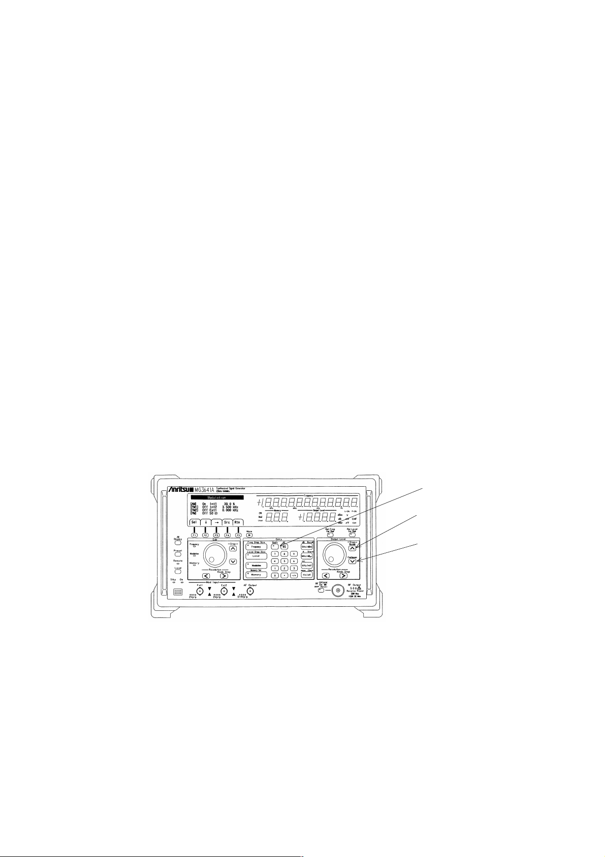
SECTION 4 OPERATING INSTRUCTIONS
4.5.4 Level Continuous Mode
This signal generator employs a mechanical attenuator to vary the output level. For this reason, momentary signal
interruptions and spike noise may be produced when you vary the output level.
Therefore, you select the level continuous mode in the cases where such momentary signal interruptions and spike
noise pose particular problems in the measurements you are conducting.
When you activate the level continuous mode, the operation of the mechanical attenuator will be fixed, and you will
be able to change the level continuously within a maximum range of ±10 dB by using only the electronic attenuator
designed for high-resolution setting.
(1) Setting the Level Continuous Mode
Press the [Shift] key and, then, the [∨] (Continuous) key in the Output Level zone. The characters "Cont" will
appear on the Output Level indicator, indicating that the continuous mode has been set up.
The output level setting range will be limited to ±10 dB with its center at the level that existed when the continuous
mode was activated, but you can vary the level within that range, free from momentary signal interruptions or
spike noise.
(2) Clearing the Level Continuous Mode
Press the [Shift] key and, then, the [^] (Normal) key in the Output Level zone. The characters "Cont" will go out
on the Output Level indicator, indicating that the continuous mode has been cleared.
MG3641A/MG3642A front panel
[Shift] key
[ ] (Normal) key
∧
[ ] (Continuous) key
∨
4-14

4.5.5 Switching the Output Signal On/Off
You can switch on and off the output signal that goes through the output connector by pressing the [RF Off/On] key.
When the output signal is cut off, the lamp of the [RF Off/On] key will light up.
An output level you set with the output signal cut off will become effective the next time you switch on the output
signal.
MG3641A/MG3642A front panel
SECTION 4 OPERATING INSTRUCTIONS
[RF Off/On] key
4-15

SECTION 4 OPERATING INSTRUCTIONS
4.5.6 Special Functions Related to Level
The signal generator offers the following functions as special functions related to the setting of output levels. You
activate these functions through the "System (2)" menu.
(1) Level Safety Mode
This unit uses a mechanical attenuator to vary the output level. For this reason, momentary signal interruptions
and spike noise may be produced when you vary the output level.
In the measurements where a spike-like high level poses a particular problem, the level continuous mode described
in Paragraph 4.5.4 will be a solution for you. However, if you need to vary the level over a wide range, you will
have to opt for the level safety mode described in this paragraph.
This level safety mode requires that you once narrow the level and then set up a level again, before you can vary
it. This necessarily involves momentary signal interruptions, and affects the level setting time, but does not give
rise to spike-like high level.
(2) Display of voltage unit
The voltage of the output level is displayed in two ways: terminated-voltage display and open-voltage display.
The terminated-voltage display indicates a voltage that holds when a 50 Ω resistance is coupled to the output end,
and the open-voltage display shows a voltage that exists when the output end is left open. The open voltage
assumes a value twice that of the terminated voltage.
To execute a special function related to the output level, follow the procedure detailed below.
(3) Isolation mode
When using multiple signal generators with the summed output signal for the measurement of the inter-modulation
distortion of an amplifier etc., the inter-modulation distortion of the summed output signal may disturbs the
measurement due to the interfererence between the signal-generator outputs of low isolation.
In this case, it is desired to increase the signal isolation between the signal generators for suppressing the distortion.
The MG3641A/MG3642A has the isolation mode to increase the isolation by increasing the attenuation amount
of the last-output-stage circuit.
This isolation mode has the following advantages and disadvantages. Understand these features before use.
• Advantages: Improves intermodulation distortion.
Improves floor noise.
• Disadvantages: Deteriorates output level accuracy.
Deteriorates higher harmonic distortion.
Deteriorates AM modulation characteristics.
4-16

SECTION 4 OPERATING INSTRUCTIONS
(1) Press the "Sys" [F3] key in the main menu (2) to open
the "System (1)" menu.
(2) Press the [More] key to move on to the "System (2)"
menu.
(3) Select "Voltage unit", "Level mode" or "Isolation mode"
by pressing the " ↓ " [F2] key or " ↑ " [F3] key (the
status display will be highlighted).
(4) Press the "Sel" [F1] to change the setting.
MainMenu(2/2)
Chk SysGPIB Opt Trig
1
System(2/2)
[Voltageunit]
[Levelmode]
[Isolationlmode]
EMF
Hi-Speed
Off
Sel Rtn
34
4-17

SECTION 4 OPERATING INSTRUCTIONS
4.6 Setting the Modulation
4.6.1 Outline of Modulation
This signal generator provides AM and FM modulation functions. The FM modulation has two systems: FM1 and
FM2, frequency deviation of which can be set independently of each other.
This unit also comes with 5 different modulation signal sources, as shown below, and you can select any one of
them for each type of modulation.
Internal modulation : Int1 ........ Sine wave of 1 kHz or 400 Hz
External modulation : Ext1 ....... Signal supplied to the Mod Input Ext1 connector
The flow of modulation signals is graphically presented below:
Modulation Source Selection Matrix
1 kHz/400 Hz
sine-wave
oscillator
Int1
Int2 ........ 0.01 Hz to 400 kHz digital synthesizer
Int3 ........ 0.01 Hz to 400 kHz digital synthesizer
Ext2 ....... Signal supplied to the Mod Input Ext2 connector
FM1 frequency
Polarity
switching
deviation setting
+
−
Internal
modulation source
2
(Option)
Internal
modulation source
3
(Option)
Mod Input
Ext1
Int2
Int3
Ext1
Ext2
Ext2 AF Output
Polarity
switching
Polarity
switching
FM2 frequency
deviation setting
+
−
AM modulation
factor setting
+
−
AF output level setting
Σ
FM modulator
AM modulator
Flow of Modulation Signals
4-18

SECTION 4 OPERATING INSTRUCTIONS
4.6.2 Setting the Modulation Function
You select activation/deactivation of each modulation type and a modulation signal source always through the
"Modulation" menu.
(1) Press the [Modulation] key or Main Menu (1) "Mod" [F1] key to open the "Modulation" menu.
MG3641A/MG3642A front panel
[Modulation] key
(2) Select the set item you need to change by operating the
"↓" [F2], and "→" [F3] keys (the characters are
highlighted).
(3) Press the "Sel" [F1] key to change the current setting.
• Modulation function: On/Off
• Modulation signal source: Int1/Int2/Int3/Ext1/Ext2
Modulation
[AM]
[FM1]
[FM2]
[PM]
Sel Rtn
3 2
OffInt1
OffInt1
OffInt1
Off50Ω
0.0
0.000
0.000
Src
%
kHz
kHz
4-19
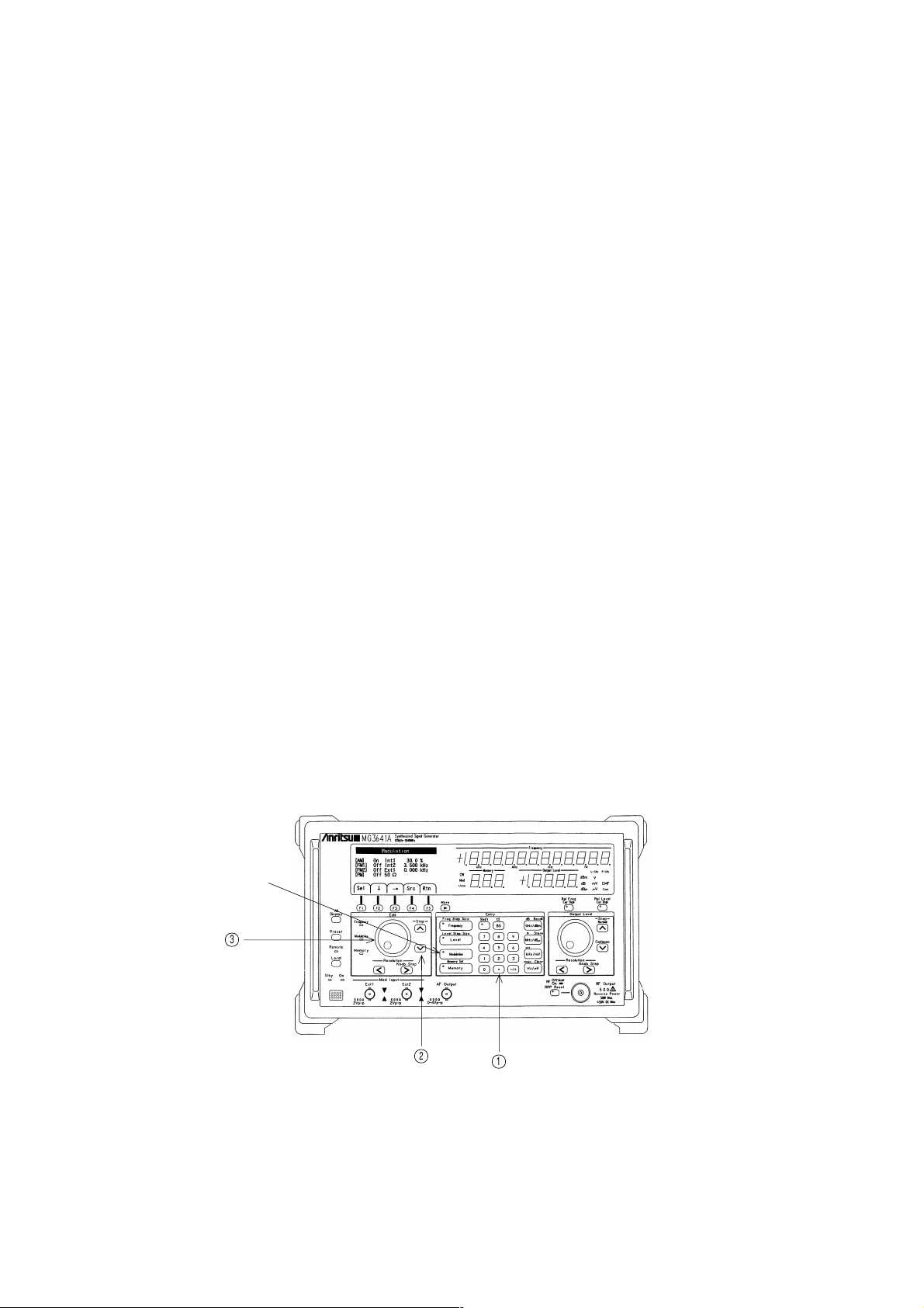
SECTION 4 OPERATING INSTRUCTIONS
4.6.3 Setting the Modulation Factor and Frequency Deviation
You set an AM modulation factor or FM frequency deviation by operating the number keys, step keys and the rotary
knob.
Pressing the [Modulation] key in the Entry zone turns on the lamp of the [Modulation] key and the Modulation lamp
of the Edit zone, allowing to set an AM modulation factor or FM frequency deviation via the step keys and rotary
knob in the Edit zone.
You select an AM modulation factor or FM frequency deviation in the "Modulation" menu opened by pressing the
[Modulation] key. The AM modulation factor or FM frequency deviation set in this way is applied to the modulation
of the item currently selected. Therefore, select a modulation function after moving the set item.
(1) Setting by number keys
You use the number keys to enter numeric values and units.
(2) Setting by step keys
You operate the step keys [^][∨] to step up or down an AM modulation factor or FM frequency deviation.
The step size becomes as follows for each modulation:
• AM modulation factor : The step size is fixed to 10 %.
• FM frequency deviation : A frequency deviation is doubled by a step-up increment, or reduced to 1/2 by a step-
down decrement.
(3) Setting by rotary knob
Turning the rotary knob raises or lowers the AM modulation factor or FM frequency deviation.
The resolution assumes the lowest position of the display both in AM modulation factor and FM frequency deviation.
MG3641A/MG3642A front panel
[Modulation] key
3
2
1
4-20

4.6.4 Setting Range of FM Frequency Deviation
In setting an FM frequency deviation, you can set it up to maximum 2048 kHz, irrespective of the output frequency.
However, the actual FM frequency deviation is restricted by the output frequency, as shown in the table below. If
you make a setting in excess of this limit, the "Uncal" lamp will come on, indicating that the range was surpassed,
and, at the same time, the deviation will be set to the maximum value of the FM frequency deviation range
corresponding to the current output frequency.
Output Frequency FM Frequency Deviation Range
≥125 kHz, <250 kHz 0 to 125 Hz
≥250 kHz, <500 kHz 0 to 250 Hz
≥500 kHz, <1 MHz 0 to 500 Hz
≥1 MHz, <2 MHz 0 to 1 kHz
≥2 MHz, <4 MHz 0 to 2 kHz
≥4 MHz, <8 MHz 0 to 4 kHz
≥8 MHz, <16 MHz 0 to 10 kHz
≥16 MHz, <32 MHz 0 to 25.6 kHz
≥32 MHz, <64 MHz 0 to 51.2 kHz
≥64 MHz, <128 MHz 0 to 102 kHz
≥128 MHz, <256 MHz 0 to 256 kHz
≥256 MHz, <512 MHz 0 to 512 kHz
≥512 MHz, ≤1040 MHz 0 to 1024 kHz
>1040 MHz, ≤2080 MHz 0 to 2048 kHz
SECTION 4 OPERATING INSTRUCTIONS
4.6.5 Polarity of Modulation Signal
You can switch the polarity of modulation signals independently for each type of modulation.
Modulation signals are usually of non-inverted polarity. Yet, they invert the polarity as you set an AM modulation
factor or FM frequency deviation in a negative value through the number keys.
For example, if you set the AM modulation factor to −30 %, you obtain an AM of 30 % modulation factor with
modulation signals in inverted polarity.
The inversion and non-inversion cannot be switched by the step keys or rotary knob.
4-21

SECTION 4 OPERATING INSTRUCTIONS
4.6.6 Pulse Modulation
The pulse modulator (an option) can be built into the MG3641A/MG3642A.
The pulse modulator can apply modulation with TTL level signals applied to the "Pulse Mod Input" connector. It
works fixed at positive logic, and the input impedance can be selected between 50 Ω and 600 Ω.
Set up the pulse modulation through the "Modulation" menu, as in the case with AM and FM.
MG3641A/MG3642A rear panel
Pulse Mod Input
connector
(1) Press the [Modulation] key to open the "Modulation" menu.
MG3641A/MG3642A front panel
[Modulation] key
4-22

(2) Select the item you need to change (ON/OFF or
impedance) in the "PM" line by the "↓" [F2], and "→"
[F3] keys (the characters are highlighted).
(3) Press the "Sel" [F1] key to change the setting.
• Modulation function: On/Off
• Impedance: 50 Ω/600 Ω
SECTION 4 OPERATING INSTRUCTIONS
Modulation
[AM]
[FM1]
[FM2]
[PM]
OffInt1
OffInt1
OffInt1
50Ω
Off
0.0
0.000
0.000
%
kHz
kHz
Sel Rtn
3 2
Src
CAUTION
If the pulse modulation and AM are activated simultaneously, the AM modulation will not be applied normally.
Feeding a voltage higher than +8 V or lower than −3 V to the "Pulse Mod Input" connector could result in
breakdown of the unit. Be careful to prevent a voltage outside the limits from entering the unit.
4-23

SECTION 4 OPERATING INSTRUCTIONS
4.7 Setting the Modulation Signal Source
4.7.1 Internal Modulation Signal (Int1)
Int1 is a signal source that generates sine waves at a frequency of either 1 kHz or 400 Hz.
To select a frequency for Int1, follow the procedure detailed below:
(1) Press the "Src" [F4] key in the Modulation Menu to
open the "Audio Source" menu.
Modulation
(2) Select frequency display for Int1 by operating the "↓"
[F2], and "↑" [F3], "→" [F4], keys (the characters are
highlighted).
(3) Press the "Sel" [F1] key to select 400 Hz or 1 kHz.
[Int1]
[Int2]
[Int3]
[Ext1]
[Ext2]
OffInt1
OffInt1
OffInt1
600Ω
Off
AudioSource
1kHz
1000.00Hz
1000.00Hz
AC-Couple
AC-Couple
Src
1
0.0
0
0
3
%
Hz
Hz
Sin
Sin
Sin
[AM]
[FM1]
[FM2]
[PM]
Sel Rtn
4-24
Sel Rtn
32

4.7.2 Internal Modulation Signals (Int2, Int3)
Int2 and Int3 are options. The following description of Int2 and Int3 assumes that AF Synthesizer (opt21) is
mounted in them both. If another option is mounted, follow the operation description in the operation manual of
that option.
AF Synthesizer are digital synthesizers that are capable of generating sine waves, triangular waves, sawtooth waves
and square waves at any frequency.
To set up a frequency and waveform, follow the procedure detailed below:
SECTION 4 OPERATING INSTRUCTIONS
(1) Press the "Src" [F4] key in the Modulation Menu to
open the "Audio Source" menu.
(2) Select frequency display for Int2 or Int3 by operating
the "↓" [F2], "↑" [F3], and "→" [F4] keys (the characters
are highlighted), and set up a frequency by the step keys
or the rotary knob in the Edit zone, and number keys.
(3) Select waveform display for Int2 or Int3 by operating
the "↓" [F2], "↑" [F3], and "→" [F4] keys (the characters
are highlighted), and press the "Sel" [F1] key to select a
waveform.
Modulation
[AM]
[FM1]
[FM2]
[PM]
Sel Rtn
[Int1]
[Int2]
[Int3]
[Ext1]
[Ext2]
Sel Rtn
OffInt1
OffInt1
OffInt1
600Ω
Off
AudioSource
1kHz
1000.00Hz
1000.00Hz
AC-Couple
AC-Couple
Src
1
0.0
0
0
Sin
Sin
Sin
%
Hz
Hz
2
3
32
When you set a frequency via the step keys, the step size will be equal to the resolution position on the rotary knob.
Select the position by which you want to step up or step down by the Resolution [<] and [>] keys.
、
3
4-25

SECTION 4 OPERATING INSTRUCTIONS
4.7.3 External Modulation Signals (Ext1, Ext2)
Ext1 and Ext2 apply modulation using external signals supplied to the "Ext1" and "Ext2" connectors (600 Ω
impedance) of Mod Input on the front panel.
The AM modulation factor or FM frequency deviation matches the relevant preset value, when the external signals
applied to the "Ext1" and "Ext2" connectors assume a level of 2 Vp-p. Adjust the external signal level in such a
manner that the " " and " " lamps located to the right of the "Ext1" and "Ext2" connectors, respectively, will both
go out.
MG3641A/MG3642A front panel
ModInput
Ext1 Ext2
600Ω
2Vp–p
600Ω
2Vp–p
If the lamp lights: The input level is too low. Raise the input level.
If the lamp lights: The input level is too high. Lower the input level.
If the frequency of the modulation input signal is 100 Hz or less, adjust the signal level so that and alternately
turns ON.
4-26

SECTION 4 OPERATING INSTRUCTIONS
For the external modulation input, you can select either DC coupling or AC coupling by following the procedure
detailed below:
(1) Press the "Src" [F4] key in the Modulation menu to open
the "Audio Source" menu.
Modulation
(2) Select coupling display for Ext1 or Ext2 by operating
the "↓" [F2], "↑" [F3], and "→" [F4] keys (the characters
are highlighted).
(3) Press the "Sel" [F1] key to change the setting.
[AM]
[FM1]
[FM2]
[PM]
Sel Rtn
[Int1]
[Int2]
[Int3]
[Ext1]
[Ext2]
Sel Rtn
OffInt1
OffInt1
OffInt1
600Ω
Off
AudioSource
1kHz
1000.00Hz
1000.00Hz
AC-Couple
AC-Couple
Src
1
0.0
0
0
Sin
Sin
Sin
%
Hz
Hz
3
3
2
CAUTION
Applying a signal at a voltage higher than ±10 V to the "Ext1" or "Ext2" connector could result in breakdown
of the unit. Be careful to prevent a signal level outside the limits from entering the unit.
4-27

SECTION 4 OPERATING INSTRUCTIONS
1
4.8 Setting the AF Output
Any one out of the internal modulation signals (Int1, Int2, Int3) and external modulation signals (Ext1, Ext2) of the
modulation signal sources can be delivered through the "AF Output" connector on the front panel.
MG3641A/MG3642A front panel
AF Output connector
You select a signal source to supply signals from by following the procedure detailed below:
(1) Press the "AF" [F3] key in the top menu to open the
"AF Output" menu.
Mod Ofs MemAFSwp
MainMenu(1/2)
4-28
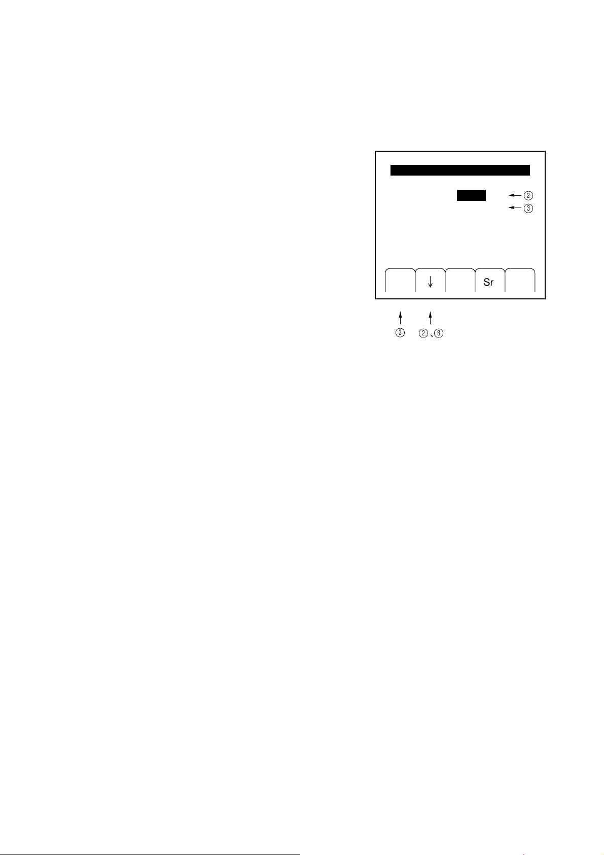
SECTION 4 OPERATING INSTRUCTIONS
、3
(2) Select "Source" by pressing the "↓" [F2] key (the
characters are highlighted), and hold down the "Sel"
[F1] key to select the signal you want delivered.
[Source]
[Level]
(3) Press the "↓" [F2] key to select "Level" (the characters
are highlighted), and set the AF output level by the
number keys, and the set keys and rotary knob in the
Edit zone.
When you set an AF level via the step keys, the step size will be equal to the resolution on the rotary knob. Select the
position by which you want to step up or step down by operating the Resolution [<] and [>] keys.
Since the "AF Output" connector has an output impedance of 600 Ω, the level you have set here will be the one
corresponding to a termination with 600 Ω.
Sel Rtn
3
AFOutput
2
Int1
1.000
mV
Src
2
3
4-29

SECTION 4 OPERATING INSTRUCTIONS
4.9 Memory Functions
4.9.1 Outline of Memory Functions
This signal generator comes with a memory function capable of storing 1000 different panel settings. The memories
are assigned to addresses from 000 to 999, and are divided into 20 blocks, each consisting of 50 memories, as
indicated below:
Block 1: Memory address 000 to 049 Block 2: Memory address 050 to 099
Block 3: Memory address 100 to 149 Block 4: Memory address 150 to 199
Block 5: Memory address 200 to 249 Block 6: Memory address 250 to 299
Block 7: Memory address 300 to 349 Block 8: Memory address 350 to 399
Block 9: Memory address 400 to 449 Block 10: Memory address 450 to 499
Block 11: Memory address 500 to 549 Block 12: Memory address 550 to 599
Block 13: Memory address 600 to 649 Block 14: Memory address 650 to 699
Block 15: Memory address 700 to 749 Block 16: Memory address 750 to 799
Block 17: Memory address 800 to 849 Block 18: Memory address 850 to 899
Block 19: Memory address 900 to 949 Block 20: Memory address 950 to 999
Normally, these divided memories can be handled as a series of 1000 memories, without this division being noticed
in particular. However, when you recall memory contents continuously via the rotary knob or step keys, some
memories can be excluded from the recall by blocks.
One memory recalling mode lets you recall frequencies only, or frequencies and output levels only. This allows to
make the memory recall faster.
4.9.2 Storing in the Memory
To store settings in the memory, first establish the panel settings in the way you want stored and, then, follow the
procedure below:
[Shift] key, [Memory] (Memory Set) key, number keys, and [MHz/dBµ] (Store) key.
Enter an address in not more than 3 digits. Address 001 may be entered in either of the following forms: [0][0][1],
[0][1] or [1].
[Shift] key
[Memory]
(Memory Set) key
(Address)
MG3641A/MG3642A front panel
4-30

4.9.3 Recalling Memory Contents
You can recall memory contents by operating the number keys, step keys, and the rotary knob.
Pressing the [Memory] key in the Entry zone turns on the lamp of the [Memory] key and the Memory lamp in the
Edit zone, leaving the unit ready to recall memory contents via the number keys, and the step key and rotary knob
in the Edit zone.
(1) Setting by number keys
You recall memory contents by entering numeric values (address) via number keys and the [GHz/dBm] (Recall)
key.
(2) Setting by step keys
You operate the step keys [^][∨] to step up or down memory addresses already stored in order to recall memory
contents continuously.
If any memory block was excluded from the continuous recall, all the memories of that block are skipped, and
those of the following block are recalled.
(3) Setting by rotary knob
Turning the rotary knob raises or lowers memory addresses already stored to perform memory recall continuously.
If any memory block was excluded from the continuous recall, all the memories of that block are skipped, and
those of the following block are recalled.
SECTION 4 OPERATING INSTRUCTIONS
[Memory] key
3
MG3641A/MG3642A front panel
2
1
4-31

SECTION 4 OPERATING INSTRUCTIONS
1
3
To alter the attributes of memory blocks, follow the procedure detailed below:
(1) Press the "Mem" [F5] key in the top menu to open the
"Memory Block Select" menu.
(2) Select the memory block of which attributes you need
to change, by pressing the "↓" [F2] key or "↑" [F3] key
(the characters are highlighted). (To select a memory
block not displayed, press the [More] key to bring it up
on the display.)
(3) Press the "Sel" [F1] key to change the attribute.
Memory addresses marked * are included in the
continuous memory recall. They can be excluded from
the continuous recall when you erase their "*".
MainMenu(1/2)
Mod Ofs MemAFSwp
MemoryBlockSelect
[RecallMode]
000-049*
050-099*
100-149*
150-199*
200-249*
3
All
250-299*
300-349*
350-399*
400-449*
450-499*
Sel Rtn
2
4-32

4.9.4 Clearing the Memory
To clear memory contents, follow the keystrokes shown below:
[Shift] key, [Memory] (Memory Set) key, number keys, [Hz/µV] (Clear) key
Or, to clear memories at continuous addresses in one shot, operate the keys as follows:
[Shift] key, [Memory] (Memory Set) key, number keys, [·] key, number keys, [Hz/µV] (Clear) key
Enter an address in not more than 3 digits. Address 001 may be entered in either of the following forms: [0][0][1],
[0][1] or [1].
Address
Smallest
address of the
memory to be
cleared
SECTION 4 OPERATING INSTRUCTIONS
Largest
address of the
memory to be
cleared
[Shift] key
[Memory]
(Memory Set) key
MG3641A/MG3642A front panel
4-33

SECTION 4 OPERATING INSTRUCTIONS
323
4.9.5 Selecting the Memory Recall Mode
If you limit the memory contents to be recalled to frequencies only or frequency and output levels only, you can
execute high-speed memory recall, without changing other settings (modulation, for example).
Select a memory mode by following the procedure detailed below:
(1) Press the "Mem" [F5] key in the top menu to open the
"Memory Block Select" menu.
MainMenu(1/2)
Mod Ofs MemAFSwp
(2) Select "Recall Mode" by pressing the "↓" [F2] key or
"↑" [F3] key (the state is highlighted).
(3) Select a recall mode by the "Sel" [F1] key.
All : To recall all the panel settings
Freq : To recall frequencies only
Freq&Level : To recall frequencies and output levels
1
MemoryBlockSelect
[RecallMode]
000-049*
050-099*
100-149*
150-199*
200-249*
Sel Rtn
All
250-299*
300-349*
350-399*
400-449*
450-499*
3
4-34

4.10 Sweep Functions
4.10.1 Outline of Sweep Functions
This signal generator performs sweep with respect to the frequencies, output levels, and memories. Each sweep has
the following sweeping patterns:
SECTION 4 OPERATING INSTRUCTIONS
Linear, number of points specified
Sweeps with a number of points of
frequency to be swept specified.
Frequency sweep
Output level sweep
Memory sweep
Start frequency/stop frequency
Sweeps with a sweep start frequency
and a sweep end frequency specified.
Center frequency/span frequency
Sweeps with a center frequency
and a width of frequencies to be
swept specified.
Start level/stop level
Sweeps with a sweep start level
and a sweep end level specified.
Center level/span level
Sweeps with a center level and
a width of levels to be swept
specified.
Start address/stop address
Performs recall successively with
a sweep start address and a sweep
end address specified.
Linear, step size specified
Sweeps with a step size of
frequency to be swept specified.
Log, multiplying factor fixed at 1 %
Sweeps with a start frequency
continuously multiplied by 1.10.
Linear, number of points specified
Sweeps with a number of points of
frequency to be swept specified.
Linear, step size specified
Sweeps with a step size of
frequency to be swept specified.
Number of points specified
Sweeps with a number of points of
level to be swept specified.
Step size specified
Sweeps with a step size of level
to be swept specified.
Number of points specified
Sweeps with a number of points of
level to be swept specified.
Step size specified
Sweeps with a step size of level
to be swept specified.
Moreover, this unit provides 3 different sweep modes, as follows:
AUTO
SINGLE
MANUAL
...
Sweeps repetitively from sweep start point to sweep end point.
...
Sweeps just once from sweep start point to sweep end point.
...
Sweep is activated manually via the rotary knob, in accordance with a
sweep pattern.
You execute sweep after selecting a sweep pattern and setting sweep parameters. All the sweep functions can be set
through the "Sweep" menu.
4-35
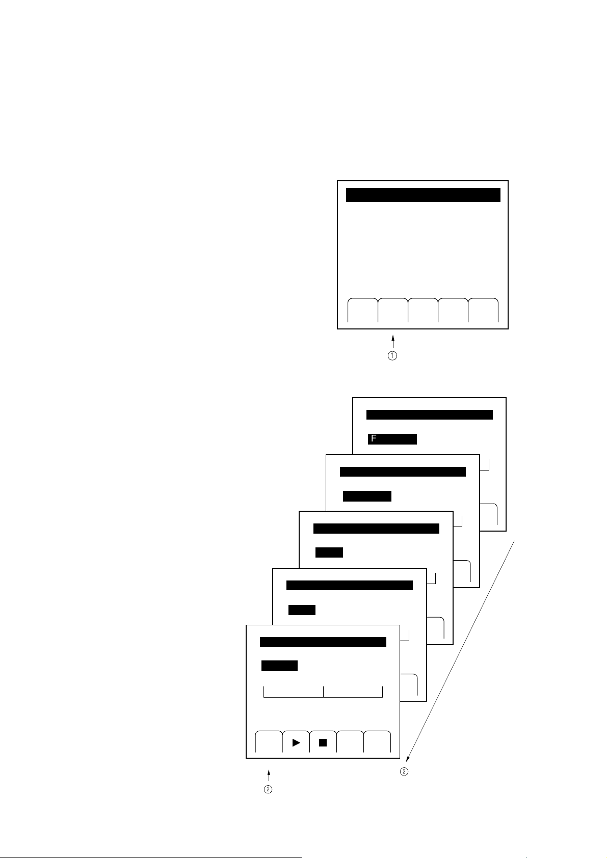
SECTION 4 OPERATING INSTRUCTIONS
4.10.2 Setting and Executing the Sweep
In the first place, you select a sweep pattern by following the procedure detailed below:
(1) Press the "Swp" [F2] key in the top menu to open the
"Sweep" menu.
(2) Press the "Sel" [F1] key to select the sweep pattern
menu.
The menus will open in the following order:
Frequency sweep (Start/Stop)
↑
Frequency sweep (Center/Span)
↑
Level sweep (Start/Stop)
↑
Level sweep (Center/Span)
↑
Memory sweep
Level<Center-Span>
0dBm
Memory
0
Sel Pram Rtn
[Marker]
MainMenu(1)
Mod Ofs MemAFSwp
1
Sweep
Frequency<Start-Stop>
0.1k
Sweep
Frequency<Center-Span>
0.1k
Sel Pram Rtn
Sweep
Level
<Start-Stop>
0dBm
Sel Pram Rtn
Sweep
10dBm
Sel Pram Rtn
Sweep
0
999
520M
20dBm
20dBm
0
1040M
1040M
4-36
Sel Prmt Rtn
2
2
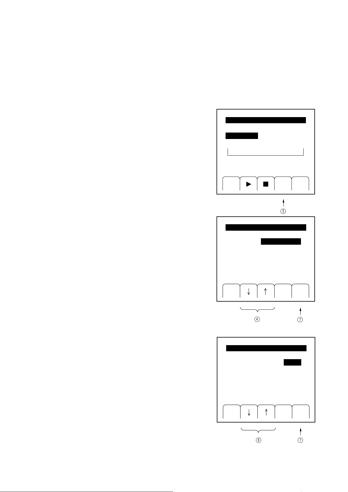
SECTION 4 OPERATING INSTRUCTIONS
3
Then, you set up sweep parameters. The following explanation assumes that the frequency sweep (Start/Stop) was
selected for the sweep pattern.
(3) Press the "Prmt" [F4] key in the "Sweep" menu to open
the "Sweep Parameter (1) " menu.
(4) Select the sweep parameter item to be changed, by
pressing the "↓" [F2] key or "↑" [F3] key (the characters
are highlighted). If the parameter item is a numeric
value, operate the number keys and the step keys and
rotary knob in the Edit zone to set the value.
To select a status, press the "Sel" [F1].
Sweep
Frequency
<Start-Stop>
0.1k
[Marker]
Sel Prmt Rtn
0.1k
1040M
FreqSweepParameter(1)
[Start]
[Stop]
1040000000.00
[Pattern]
[StepSize]
[Marker]
125000.00
Lin-△F
5000.00
520000000.00
Hz
Hz
Hz
Hz
(5) Press the [More] key to move on to the "Sweep
Parameter (2)" menu. (This menu is not involved in
setting parameters for memory sweep.)
(6) Select the sweep parameter item to be changed, by
pressing the "↓" [F2] key or "↑" [F3] key (the characters
are highlighted). If the parameter item is a numeric
value, operate the number keys and the step keys and
rotary knob in the Edit zone to set the value.
To select a status, press the "Sel" [F1].
Sel Rtn
4
7
FreqSweepParameter(2)
[Mode]
[Time]
10ms/step
Auto
Sel Rtn
67
4-37

SECTION 4 OPERATING INSTRUCTIONS
Once you have set the sweep parameters, you execute the sweep.
(7) Press the "Rtn" [F5] key in the "Sweep Parameter" menu
to return to the "Sweep" menu.
(8) Pressing the " " [F2] key starts the sweep.
(9) Pressing the "■" [F3] key with the sweep under way
aborts the sweep.
Moreover, pressing " " key will hold the sweep
temporarily. Another press to the [F2] key will resume
the sweep.
During hold, the [F2] key is displayed as .
4.10.3 Sweep Auxiliary Outputs
While the signal generator performs sweep, it outputs signals that are synchronized to the sweep through the four
connectors located on the rear panel, as follows:
Sweep
Frequency
<Start-Stop>
0.1k
[Marker]
Sel Prmt Rtn
8
Frequency
<Start-Stop>
0.1k
[Marker]
Sel Prmt Rtn
0.1k
Sweep
0.1k
1040M
1040M
(1) X Out
Outputs sawtooth waves that are at 0 V at the sweep start point, and at +10 V at the sweep end point.
(2) Z Out
Outputs "H"-level TTL signals while it continues with sweep.
(3) Blanking Out
Outputs "H"-level TTL signals every sweep step, from the time when hardware setting is completed, till the next
step setting begins
(4) Marker Out
Outputs "H"-level TTL signals when the actual sweep matches the marker point which was set in the "Sweep
Parameter" menu.
4-38
9

4.10.3 Sweep Auxiliary Outputs
While the signal generator performs sweep, it outputs signals that are synchronized to the sweep through the four
connectors located on the rear panel, as follows:
(1) X Out
Outputs sawtooth waves that are at 0 V at the sweep start point, and at +10 V at the sweep end point.
(2) Z Out
Outputs "H"-level TTL signals while it continues with sweep.
(3) Blanking Out
Outputs "H"-level TTL signals every sweep step, from the time when hardware setting is completed, till the next
step setting begins
(4) Marker Out
Outputs "H"-level TTL signals when the actual sweep matches the marker point which was set in the "Sweep
Parameter" menu.
SECTION 4 OPERATING INSTRUCTIONS
MG3641A/MG3642A rear panel
Sweep Auxiliary
Output Connector
4-39

SECTION 4 OPERATING INSTRUCTIONS
The diagram below represents the timing of each sweep auxiliary output.
Sweep start point Marker point Sweep end point
+10V
X Out
0V
H
Z Out
L
Sweep
Blanking Out
Marker Out
H
L
H
L
4-40

4.11 Trigger Function
4.11.1 Outline of trigger function
The trigger function executes the panel key operation procedures registered beforehand as the trigger program by
the external trigger signal. The same measurement procedures can be repeated easily from the operator panel or
external device by registering the procedures as the trigger program.
For example, if the Step [^] key of the Output Level zone is registered in the trigger program, the output level can be
stepped up each time the trigger is input.
All keys except for the [Preset] key, [Local] key, rotary knobs, and [Stby/On] key can be registered in the trigger
program.
To execute the trigger program, generate the trigger signal as follows:
• Input a negative logical pulse from the Trig Input connector on the rear panel.
• Use GPIB to send the *TRG command or execute the trigger interrupt function.
• Press the "Exe" [F4] key of the "Trig Program" menu.
SECTION 4 OPERATING INSTRUCTIONS
4-41

SECTION 4 OPERATING INSTRUCTIONS
1
4.11.2 Registering the trigger program
Register the trigger program as follows:
(1) Press the "Trig" [F5] key on the Main Menu (2) to open
the "Trigger Program" menu.
MainMenu(2/2)
(2) Press the "Enter" [F3] key. The screen switches to the
Main Manu (1) and the device enters the trigger program
registration state.
Subsequent key operations are registered as the trigger
program (the message "Trigger Program Entry" is
displayed to indicate that a key operation is being regi-
stered.
(3) To terminate registering the trigger program, press the
"Trig" [F5] key on the Main Menu (2) again to open
the "Trigger Program" menu. Registering the trigger
program terminates when the "Trigger Program" menu
is opened.
Chk Trig
GPIB Sys
TriggerProgram
NoTrigProgram
Clr Rtn
TriggerProgram
SYSTBELLOFF
FREQSWETYPE0
FREQSWEPATTLOG
FREQSWESTAR1MHz
FREQSWESTOP100MHz
Opt
ExeEntr
2
4-42
Clr Rtn
ExeEntr
3

If the trigger program is registered when another trigger program is already registered, the new trigger program is
added to the already-registered trigger program. To register a new trigger program, press the "Clr" [F1] key to erase
the already-registered trigger program before using the "Entr" [F3] key to enter the registration state in Item (2)
above.
When a key is operated while the trigger program is being registered, the function is set as a usual panel operation,
but sweep is not executed. The maximum number of trigger program steps (functions) is 20. A trigger program of
more than 20 steps cannot be registered. If the number of steps exceeds 20, the message "Trigger entry overflow"
is displayed. In this case, open the "Trigger Program" menu and terminate registering the trigger program. Even if
the number of steps exceeds 20, the registration state is not canceled automatically.
If no key is operated for 30 seconds or longer while the trigger program is being registered, the registration state is
canceled automatically. In this case, the trigger program is not registered.
The sweep mode in which sweep is executed in the trigger program is forcibly set to SINGLE sweep.
4.11.3 Executing the trigger program
Execute the trigger program in one of the following ways:
SECTION 4 OPERATING INSTRUCTIONS
(1) Execution by the external logic signal
Execute the trigger program at the falling edge of the TTL level signal input from the Trig Input connector on the
rear panel. Because this connector is pulled up internally, the trigger program can be executed by simply connecting
the connector to the ground.
TrigInput
Switch
TTL
(2) Execution using GPIB
The trigger program can be executed by sending the *TRG command or executing the trigger interrupt function
from GPIB.
For GPIB, see Section 6, "Remote control using GPIB."
4-43

SECTION 4 OPERATING INSTRUCTIONS
g
[
(3) Execution using the panel key
When the "Exe" [F4] key on the "Trigger Program" key
is pressed, the trigger program is executed. This method
can be used to check the trigger function.
TriggerProgram
SYSTBELLOFF
FREQSWETYPE0
FREQSWEPATTLOG
FREQSWESTAR1MHz
FREQSWESTOP100MHz
The trigger program can be halted by pressing a key other than the [Preset] or [Local] key on the panel.
4.11.4 Checking the contents of the trigger program
The contents of the trigger program can be checked by opening the "Trigger Program" menu. In the trigger program,
one step is displayed as one line. If the trigger program consists of more than one page, a page number is displayed
in the menu title. In this case, press the [More] key to advance to the next page.
TriggerProgram(1/2)
SYSTBELLOFF
FREQSWETYPE0
FREQSWEPATTLOG
FREQSWESTAR1MHz
FREQSWESTOP100MHz
Clr Rtn
Executin
TriggerProgram(2/2)
FREQSWETIME100ms
FREQSWERUN
ExeEntr
thetriggerprogram
4-44
Clr Rtn
ExeEntr
Clr Rtn
More]キー
ExeEntr

4.12 Miscellaneous Functions
4.12.1 Setting Display On/Off
The MG3641A/MG3642A has a low EMI radiation from the panel, and it does not become a problem at a ordinary
measurement.
However, if the radiation affects the measurement, it can be eliminated by pressing the [Display] key to turn off
the multi-menu display.
To turn off all the frequency, output level etc. displays, press the [Shift] and then [Display] keys.
To turn on the display again, perform the same key operation.
[Display] key
SECTION 4 OPERATING INSTRUCTIONS
MG3641A/MG3642Afront panel
[Shift] key
4-45

SECTION 4 OPERATING INSTRUCTIONS
3
1
4.12.2 Setting Bell • Alarm On/Off
Bell (bell sound when any panel key is pressed, or the rotary knob is revolved.) • alarm (alarm sound when any
error is occurred.) On/Off can be set as follows.
(1) Press the "Sys" [F3] key on the top menu to open the
"System (1)" menu.
(2) Press the "↓" [F2] key or "↑" [F3] key, to select "Bell"
or "Alarm".
(State is reverse-displayed.)
(3) Press the "Sel" [F1] key to select On or Off.
MainMenu(2/2)
Chk SysGPIB Opt Trig
System(1/2)
Factoryinitiarize
Initialmemoryset
Initialmemoryclear
[Bell]
[Alarm]
Off
On
Sel Rtn
2
4-46

4.12.3 Setting address and only mode of GPIB
1
The MG3641A/MG3642A has the GPIB only mode.
The GPIB address and only mode are set on the GPIB menu, as described below.
SECTION 4 OPERATING INSTRUCTIONS
(1) Press the “GPIB” [F2] key on the top menu to open the
“GPIB” menu.
(2) Press the “↓” [F2] key or “ ↑” [F3] key to select
“Address”.
(Address is reverse displayed.)
Set the address with numeric keys, and confirm the value
with any unit key.
MainMenu(2/2)
Chk SysGPIB Opt Trig
GPIB
[Address]
[Mode]
3
Talker&Listener
2
(3) Press the “↓” [F2] key or “↑” [F3] key to select “Mode”.
(State is reverse displayed.)
Press the “Sel” [F1] key to select mode, below.
• Ordinary mode: Talker&Listener
• Talk-only mode of frequency: Freq Talk
• Talk-only mode of level: Level Talk
• Talk-only mode of
frequency and level: Both Talk
3
Sel Rtn
3
2
、
3
4-47

SECTION 4 OPERATING INSTRUCTIONS
4.12.4 Panel Lock
Not to change the setting condition of this instrument at long-time continuous test etc., press the [Local] key while
pressing the [Shift] key to lock all the keys and the rotary knob.
[Local] key
MG3641A/MG3642Afront panel
[Shift] key
To remove the panel-lock condition, turn off and on the power to recover the ordinary state.
CAUTION
In panel lock mode, the GPIB and trigger functions do not work.
If the panel lock is performed during sweeping operation, the sweeping is stopped.
4-48

SECTION 4 OPERATING INSTRUCTIONS
4.13 Removing Reverse Power Protection (RPP) Circuit Operation
The MG3641A/MG3642A has a Reverse Power Protection (RPP) circuit at the RF Output circuit to protect the
internal circuit from the excessive reverse power.
When the RPP circuit operated, “RPP” is displayed at the Output Level display area, and the RF output signal is
turned off.
At that time, remove the excessive external power, and press the [Shift] and [RF Off/On] (RPP Reset) keys to
remove the RPP operation.
MG3641A/MG3642A front panel
[Shift] key
[RF Off/On] (RPP Reset) key
CAUTION
• The RPP circuit uses a mechanical switch. If many times of the operations are occurred, the switch contact
is consumed. So, don’t apply the excessive power to the RF Output connector, as possible.
• Don’t remove the RPP circuit while applying an excessive power. Or the RPP circuit is damaged.
• Maximum reverse power from which the MG3641A/MG3642A can be protected, is 50 Vdc, 50 W (up to
1040 MHz) or 25 W (1040 to 2080 MHz).
• While the RPP circuit operated, the output impedance becomes the open state. So, take care of the connected device under test.
4-49

SECTION 4 OPERATING INSTRUCTIONS
4.14 Error Messages
If a panel operation or device internal error occurs, the MG3641A/MG3642A displays messages in the error message
area on the multimenu display.
MainMenu(1/2)
Errormessages
Dataoutofrange
Swp AF
Mod Ofs Mem
Error messages are given below:
Operation error: Displayed when a setting becomes invalid because of an incorrect operation.
Data out of range: An attempt is made to set a value out of range
(e.g., to set the frequency to 10 GHz).
Invalid suffix: A unit key not appropriate for a set parameter is pressed
(e.g., an attempt is made to set the sweep time to 1 MHz)
Execution error: An attempt is made to execute one of the following incorrect operations:
• To start executing the sweep with an incorrect sweep parameter specified.
• To display too many digits on the display unit for the output level offset in
volts.
• To exceed the upper limit of the variance range (±10 dB) in level continuous
mode.
Not Stored memory: An attempt is made to recall a memory not stored.
Trigger entry overflow: An attempt is made to register a trigger program of more than 20 steps.
Trigger entry ignored: An attempt is made to register the trigger program when sweep is being executed
or suspended.
4-50
Hardware error: An attempt is made to execute settings relating to an unmounted option
(e.g., to turn on pulse modulation when the pulse modulator is not mounted.)

SECTION 4 OPERATING INSTRUCTIONS
Hardware status: Displayed when the MG3641A/3642A is used incorrectly or fault occurs.
RF out shut-down by RPP: The reverse power protection circuit operates.
→ Eliminate the cause and cancel the operation of the reverse power protec-
tion circuit (see paragraph 4.13).
Reference signal abnormal: The reference signal is abnormal.
→ The frequency or level of the signal input as an external reference signal is
inappropriate. Input a suitable reference signal.
Synthesizer unlock: The synthesizer is unlocked.
→ If this message does not go off after warming up, a failure may occur in the
circuit. Request the synthesizer be repaired.
RF Amplifier abnormal: An output level is abnormal.
→ This message is displayed when a setting exceeds the limit of the output
amplifier of the final step. In this state, the level identical to the display is
not output. If this message is displayed within the level accuracy guarantee
range (+17 dBm or less), a fault may have developed. Request the output
amplifier be repaired.
When the output amplifier is normal, but the output connector is not impedance-matched, severely (for example, open or short state); this message
may be displayed.
Setting outside performance guarantee range: This message is displayed if a value is set outside the performance
guarantee range.
Level uncal: A value is set outside the output level accuracy guarantee range.
→ Even if this message is displayed, the output level is usually accurate pro-
vided that the message "RF Amplifier Abnormal" is not displayed.
FM uncal: FM deviation is set outside the setting range.
→ The setting range of the FM deviation depends on the carrier frequency. If
the FM deviation setting range at the current carrier frequency is exceeded,
this message is displayed and the FM deviation becomes that of the upper
limit of the setting range.
AM uncal: The AM modulation is set outside the guarantee range.
→ This message is displayed if the AM modulation is set outside the perfor-
mance guarantee range.
Except for the above cases, various types of errors during remote control using GPIB are also displayed. For error
messages relating to GPIB, see paragraph 6.5.5, "SCPI error messages."
4-51

SECTION 4 OPERATING INSTRUCTIONS
(Blank)
4-52 .

SECTION 5 MEASUREMENT
SECTION 5
MEASUREMENT
5.1 Measurement of Sensitivity
The sensitivity of the receiver means the minimum signal input level required to output the rated signal of the receiver.
The following incidental conditions are required for the signal level, noise level, and signal distortion obtained in the
output side of the receiver:
• AM receiver ............. Indicated by the minimum value of the typically modulated carrier voltage required to output
the rated signal of the specified signal-noise rate (S/N). For example, when S/N = 20 dB, the
minimum value of the carrier input voltage for 60 % modulation required to output the 50-
mW signal is indicated by 10 µV.
• FM receiver.............. Indicated by the minimum value of the typically modulated carrier voltage required to obtain
the rated output and specified value (–12 dB in 400 MHz) of the signal to noise and distortion
(SINAD) obtained by adding the signal distortion to the signal-noise rate (S/N). In addition,
this sensitivity is indicated by the minimum value of the carrier voltage required to suppress
the receiver noise output by 20 dB at no-modulation. This is called a noise suppression (NQ)
sensitivity.
This section describes the latter 20 dB NQ sensitivity and explains how to measure the 12 dB SINAD sensitivity.
5-1

SECTION 5 MEASUREMENT
5.1.1 Measuring 20 dB NQ sensitivity
The 20 dB NQ sensitivity is indicated the carrier input voltage (reading value of the output voltage of the signal
generator) required to suppress the noise output by 20 dB when there is no 20 dB noise quieting, e.g., signal input.
To obtain the noise output before suppressed, adjust the volume adjustment volume of the receiver so that the rated
signal output is obtained.
(1) Setup
MG3641A/MG3642A
PseudoantennaFMreceiver
DA FM RX DL LM
(154.45MHz)
Standard
pseudo-load
Level
meter
Fig. 5-1. Measuring 20 dB NQ Sensitivity
(2) Measurement procedure
STEP PROCEDURE
1. Set the MG3641A/MG3642A frequency to 154.45 MHz.
2. Set the MG3641A/MG3642A frequency deviation to 70 % (3.5 kHz for maximum frequency deviation 5
kHz) of the specified maximum frequency deviation. Then, set the internal modulation frequency to 1 kHz.
3. Set the MG3641A/MG3642A to a sufficiently high output (ordinarily 30 dBµ or more) and apply it to the
receiver.
4. Turn off the squelch of the receiver, synchronize the receiver with receiving frequency 154.45 MHz (so that
the reading value of the level meter is the maximum), then adjust the volume adjust volume of the receiver
so that the rated output of the receiver is obtained according to the indicator of the level meter.
5. Turn off the MG3641A/MG3642A output.
6. Use the level meter to measure the receiver noise output and set the meter indicator to 0 dB.
7. Turn off the MG3641A/MG3642A modulation and turn on the MG3641A/MG3642A output.
8. Adjust the MG3641A/MG3642A output level so that the indicator of the level meter is set to –20 dB.
9. The reading value of the MG3641A/MG3642A output level indicator is a 20 dB NQ sensitivity in step 8.
5-2

5.1.2 Measuring 12 dB SINAD sensitivity
MG3641A/MG3642A
DA FM RX DL LM
(465.05MHz)
PseudoantennaFMreceiver
Standard
pseudo-load
Distortion rate
and noise meter
The SINAD sensitivity is indicated by the output level of the signal generator when the distortion rate reaches the
determined value (–12 dB in the 400 MHz zone of Japan) by reducing the output level of the signal generator while
measuring the distortion (correctly distortion + noise) of the receiving modulation output of the typically modulated
signal.
(1) Setup
SECTION 5 MEASUREMENT
(2) Measurement procedure
STEP PROCEDURE
Fig. 5-2. Measuring 12 dB SINAD Sensitivity
1. Set the MG3641A/MG3642A frequency to 465.05 MHz.
2. Set the MG3641A/MG3642A frequency deviation to 70 % (3.5 kHz for maximum frequency deviation 5
kHz) of the specified maximum frequency deviation. Then, set the internal modulation frequency to 1 kHz.
3. Set the MG3641A/MG3642A to a sufficiently high output (ordinarily 30 dBµ or more) and apply it to the
receiver.
4. Turn off the squelch of the receiver, synchronize the receiver with receiving frequency 465.05 MHz (so that
the reading value of the distortion rate and noise meter is the maximum), then adjust the volume adjust
volume of the receiver so that the rated output of the receiver is obtained according to the indicator of the
distortion rate and noise meter.
5. Adjust the MG3641A/MG3642A output level so that the indicator of the distortion rate and noise meter is
set to –12 dB.
6. The reading value of the MG3641A/MG3642A output level indicator is a 12 dB SINAD sensitivity in step
5.
5-3

SECTION 5 MEASUREMENT
5.2 Measuring the 1-signal Selectivity
The 1-signal selectivity is measured when the receiver operates in a proportional region because the expected wave
and interference disturbing wave are fine. It is indicated by the relative input voltage rate required to equalize the
output of the receiver by connecting the signal generator to the receiver input pin in the expected wave receiving state
and changing its frequency to the expected or disturbing one. This method is available to measure a pass band width,
attenuation slope, and spurious response.
5.2.1 Measuring selectivity characteristics of the FM receiver in 20 dB NQ method
This figure shows the selectivity characteristics of a
signal-channel FM receiver 146 to 162 MHz. The
80
approved values are as follows:
70
60
50
40
30
20
10
6
10 20 3030 1020 +kHz–kHz
• The characteristics curve must not be in the hatched part. The solid line is approved; the broken line is rejected.
• Pass band width ........ 6 dB (Reduction width = 20
kHz or more)
• Attenuation slope ...... 70 dB (Reduction band width =
50 kHz or less)
These conditions apply to measure the selectivity in the
20 dB NQ method as follows:
• Pass band width ........Increase the SG output by 6 dB
as compared with the NQ
sensitivity and move up or
down the frequency so that the
NQ sensitivity is obtained
again. Then, obtain this width
from its frequency width.
• Attenuation factor .....Increase the SG output by 60
dB, not 6 dB like the above.
5-4

(1) Setup
SECTION 5 MEASUREMENT
MG3641A/MG3642A
PseudoantennaFMreceiver
DA FM RX DL LM
(154.45MHz)
Standard
pseudo-load
Level
meter
Fig. 5-3. Measuring Selectivity in 20 dB NQ Method
(2) Measurement procedure (Pass band width)
STEP PROCEDURE
1. Set the MG3641A/MG3642A frequency, output level, and FM receiver setting into the 20 dB NQ sensitivity
mode.
2. Place the MG3641A/MG3642A into the relative level display mode and set the output level resolution to 1
dB.
3. Clockwise turn the rotary knob of Output to increase the MG3641A/MG3642A output level by 6 dB as
compared with the 20 dB NQ sensitivity (set the display of the output level indicator to +6 dB).
4. Set the MG3641A/MG3642A frequency resolution to 100 Hz.
5. Clockwise turn the rotary knob of Edit to reduce the frequency and adjust it until the 20 dB NQ sensitivity is
obtained again.
6. Place the MG3641A/MG3642A into the relative frequency display mode.
7. Clockwise turn the rotary knob of Edit to increase the frequency and adjust it until the 20 dB NQ sensitivity
is obtained again.
8. The value indicated by the Frequency indicator is the pass band width.
5-5

SECTION 5 MEASUREMENT
(3) Measurement procedure (Attenuation rate)
STEP PROCEDURE
1. Set the MG3641A/MG3642A frequency, output level, and FM receiver setting into the 20 dB NQ sensitivity
mode.
2. Place the MG3641A/MG3642A into the relative level display mode and set the output level resolution to 1
dB.
3. Clockwise turn the rotary knob of Output to increase the MG3641A/MG3642A output level by 70 dB as
compared with the 20 dB NQ sensitivity (set the display of the output level indicator to +70 dB).
4. Set the MG3641A/MG3642A frequency resolution to 100 Hz.
5. Clockwise turn the rotary knob of Edit to reduce the frequency and adjust it until the 20 dB NQ sensitivity is
obtained again.
6. Place the MG3641A/MG3642A into the relative frequency display mode.
7. Clockwise turn the rotary knob of Edit to increase the frequency and adjust it until the 20 dB NQ sensitivity
is obtained again.
8. The value indicated by the Frequency indicator is the pass band width that reduced by 70 dB.
5-6

5.2.2 Measuring spurious response
The spurious sensitivity reduces as the receiver output obtained at reception of the modulated desired-frequency is
different from that obtained at reception of the modulated spurious frequency. To measure the spurious response,
adjust the output level of the signal generator of the spurious frequency so that these two receiver outputs are equal.
Then, obtain that value from the difference between the output level of the signal generator of the desired frequency
and that of the signal generator of the spurious frequency.
When the desired frequency of the receiver is fd; IF frequency is fi; local frequency is fL, the following frequency
is assumed to be spurious frequency fs.
• Image frequency ......... fs = fL ±fi = fd ±2fi
• Higher harmonic ......... fs = fL ±fi/2, fs = nfd ±fi/2
If a frequency that sets the difference from the local frequency to fi/2 is input, the second
higher harmonic of fi/2 changes to an IF frequency and an interference occurs.
• Harmonic frequency of local frequency ....... fs = nfL ±fi
SECTION 5 MEASUREMENT
This section shows an example of fd = 154.45 MHz, fs = fd + 2 fi. fi = 10.7 MHz to explain the measurement
procedure.
(1) Setup
MG3641A/MG3642A
Pseudo-
antennaFMreceiver
DA FM RX DL LM
(154.45MHz)
Standard
pseudo-load
Level
meter
Fig. 5-4. Measuring Spurious Sensitivity
5-7

SECTION 5 MEASUREMENT
(2) Measurement procedure
STEP PROCEDURE
1. Set the MG3641A/MG3642A frequency to fd = 154.45 MHz.
2. Set the MG3641A/MG3642A frequency deviation to 70 % of the specified maximum frequency deviation
(3.5 kHz if the maximum frequency deviation is 5 kHz). Then, set the internal modulation frequency to 1
kHz.
3. Set the MG3641A/MG3642A to a sufficiently high output (ordinarily 30 dBµ or more) and apply it to the
receiver.
4. Turn off the squelch of the receiver, modulate the receiver to receiving frequency 154.45 MHz (maximize
the value of the level meter), adjust the volume adjustment volume of the receiver, and obtain the rated
output of the receiver from the indicator of the level meter.
5. Place the MG3641A/MG3642A into the relative frequency display mode.
6. While holding the receiver state, MG3641A/MG3642A modulation frequency, and frequency deviation to
the same, apply the spurious frequency of the receiver, fs = fd + 2 fi, to the receiver. The spurious
frequency is obtained by adding 2 × fi = 2 × 10.7 MHz in the relative frequency mode.
7. Place the MG3641A/MG3642A into the relative level mode and set the output level resolution to 1 dB.
8. Adjust the MG3641A/MG3642A output level so that the value of the level meter becomes the same as the
rated output obtained in step 4.
9. The value indicated by the MG3641A/MG3642A output level indicator in step 8 is a spurious sensitivity.
5-8
 Loading...