

Page 1

MP1570A
SONET/SDH/PDH/ATM Analyzer
SDH Edition
1.5M to 10Gbit/s
High Performance and Portable for SONET, SDH, PDH, and ATM Networks
Page 2

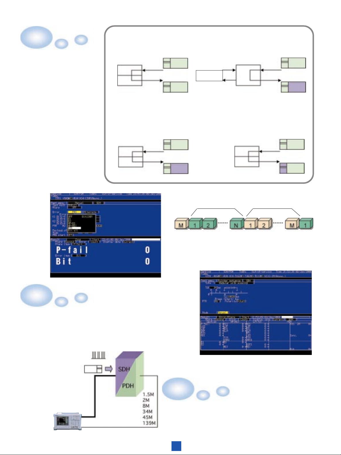
Analyzer Conforming to Bit Rates from 1.5 Mbps to 10 Gbps
Cross connect test
Transmission test
Optical
Electrical
Wireless
MUX/DEMUX test
MUX/DEMUX test
DXC
Subscriber line
ADM
ADM
ADM ADM
ADM
ADM test
system
PDH
E 1
E 2
E 3
E 4
Subscriber line
ATM test
SONET
OC–1/3/12/48/192
ATM
network
ATM
ADM test
system
DSn
DS 1
DS 2
DS 3
ATM test
ADM
ADM ADM
switch
ATM
network
ATM
SDH
STM-0/1/4/16/64
switch
The MP1570A is an analyzer designed for the manufacturing, construction, maintenance, and
inspection of SONET, SDH, PDH, and ATM equipment and networks. Various plug-in units available
for the MP1570A allow the user to construct various analysis systems for different applications.
The MP1570A has six slots to connect the plug-in units required for SDH and SONET tests at bit rates
from 1.5 Mbps to 10 Gbps. Also ATM, jitter, and wander tests can be done by appropriate
combinations of plug-in units. The MP1570A conforms to the ITU-T and Bellcore standards and
supports concatenation mapping, tandem connection, APS measurement, and CID measurement. The
user can measure 10 Gbps signals using a single MP1570A; conventionally, this required multiple
pieces of measurement equipment.
The MP1570A has a printer and a 3.5-inch floppy disk drive as standard output devices. The user can
print the measurement results, save and read data to and from a floppy disk, and read measurement data
on an external personal computer. The user can also save screen data to a floppy disk. The MP1570A
has a function to help the user understand the analyzer operations and functions and the connection
methods.
2
Page 3

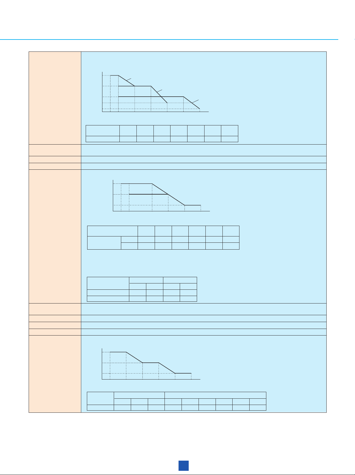
Conforming to bit rates from 1.5Mbps to
10 Gbps with a single unit
The MP1570A conforms to ITU-T Recommendations
G.703 (2, 8, 34, 139, 1.5, and 45 Mbps) and G.703 and
G.958 (52, 156, 622, 2,488, and 9,953 Mbps), allowing
the user to select plug-in units for different applications,
including SDH, ATM, and jitter tests.
Frequency and optical power
measurement
The MP1570A can measure received frequencies and
display measurement results in a graph. If an optical
interface plug-in unit is installed, the MP1570A can
measure the absolute and relative values of optical
power.
Concatenation mapping
The MP1570A can perform SDH and SONET tests
through the mapping routes from STM-1C to STM-64C.
Enhanced SDH and SONET test
functions
The MP1570A supports the generation and detection of
CID patterns (ITU-T Recommendation G.958), tandem
connection patterns (ITU-T Recommendation G.707),
and no-frame patterns and the setting and resetting of
conditions for an APS switch time test (ITU-T
Recommendations G.707, G.783, and G.842), overhead
test, and alarm detection.
Frame memory and capture (optional)
The MP1570A can be used to edit and analyze up to 64
frames of data (or up to 26 frames of data at 10 Gbps).
Enhanced through-modes
The MP1570A allows the user to select one of four
through modes: transparent through,
overhead/over-write, payload/overwrite, and
add/drop. The user can also insert various kinds of
error and alarm signals into through signals.
Jitter generation and measurement
The MP1570A can measure jitter tolerance and jitter
transfer characteristics in conformance with ITU-T
Recommendations G.823, G.824, G.825, and G.958 and
Bellcore 253 and 499. It displays measurement results
as numeric values and in a graph, allowing the user to
evaluate them easily.
Wander generation
The MP1570A can generate wander signals in
conformance with ITU-T Recommendations G.823,
G.824, and G.825 and Bellcore 253 and 499. If a
separately sold application program is installed on the
external personal computer connected, evaluation of
MTIE and TDEV is possible.
ATM pattern generation and
measurement
The MP1570A can not only test cell performance but
also measure cell delay time, CDV, and cell traffic. For
OAM testing, it can generate and detect the AIS, RDI,
and continuity check cells for F4 and F5 flows. It can
also generate the loopback and performance-monitoring
cells which conform to ITU-T Recommendation I.610.
Error analysis (error performance)
The MP1570A enables the user to perform
measurement conforming to ITU-T
Recommendations G.821, M.2100, G.826, M.2101,
M.2110, and M.2120.
Supporting SDH, SONET, and Japan
modes with one cabinet (optional)
The MP1570A allows the user to set up the
measurement of SDH, SONET, 384k, and Japan
mapping with one cabinet. For Japanese mapping
measurement, the user can set a signaling pattern
(multi-frame pattern of 8 frames or 64 frames).
3
Page 4

SONET, SDH, and PDH Measurement
Measurement at bit rates from
1.5 Mbps to 10 Gbps
The user can set a mapping route with a bit
rate of up to 10 Gbps. The MP1570A mainly
supports SDH, SONET, and Japanese
mapping for digital communication. A route
from STM-1C to up to STM-64C can be set
for concatenation mapping. Furthermore, the
MP1570A supports a combination of channels
-- for example, one channel of VC4, 16
channels of STM4C, and four channels of
STM16C. (See fig.1/P.10)
Overhead setting and testing
The user can set overhead, modify the capture and
overhead settings, and measure pointer 64 frames
and overhead bit errors.
4
Page 5

APS function
The user can test the automatic protection
switch (APS) by measuring the equipment
switching time accurately in units of
milliseconds. The MP1570A also conforms to
ITU-T Recommendations G.783 and G.841.
Mixed payload
At measurement of mapping in TUG-3 and lowerlevel layers, the user can set two additional
channels other than the measurement-target
channels.
Tandem connection
The user can set and measure N1 and N2 bytes.
5
Page 6

Various analysis functions
The MP1570A has an internal optical power meter which
allows the user to measure optical power during error and
alarm measurement without changing the connections of
the optical fiber cables. (Photo A)
The MP1570A can capture an arbitrary SOH or POH (1
byte), K1 or K2 byte, or H1 or H2 byte in 1,024 frames
for analyzing errors and alarms and for checking APS
operation. (Photo B)
Measured errors and alarms can be displayed in a graph.
The user can select a unit time of 1 second, 1 minute, 15
minutes, or 60 minutes for a bar graph. (Photo C)
Photo A
Photo B
Pointer value monitoring
Photo C
The MP1570A can display changes of pointer
value in a graph. Monitored values are updated
in real time.
MUX/DEMUX function (optional)
The MP1570A allows the user to set frames on or off at every bit rate. If the MUX/DEMUX function
is installed, the MP1570A can generate a multiplexing structure including frame alignment signals and
perform multiplexer/demultiplexer measurement.
6
Page 7
Through-mode
Transparen t:
For in-service monitoring.
Add/Drop :
Add/Drop of external DS1/DS3/PDH signals.
The user can select one
of four through-modes:
transparent,
overhead/over-write,
payload/over-write, and
add/drop.
Rx
Tx
Overhead/over-write :
Insertion of internal STS3SPE/VC4, VT6/TU2, VT2/TU12,
and VT1.5/TU11 signals.
Rx
Tx
Rx
External
DS1,DS3,PDH
Tx
Overhead/over-write :
Modification of SOH/POH byte.
Addition of various errors/alarms.
Rx
Tx
Correct frame word(N) Illegal frame word(M)
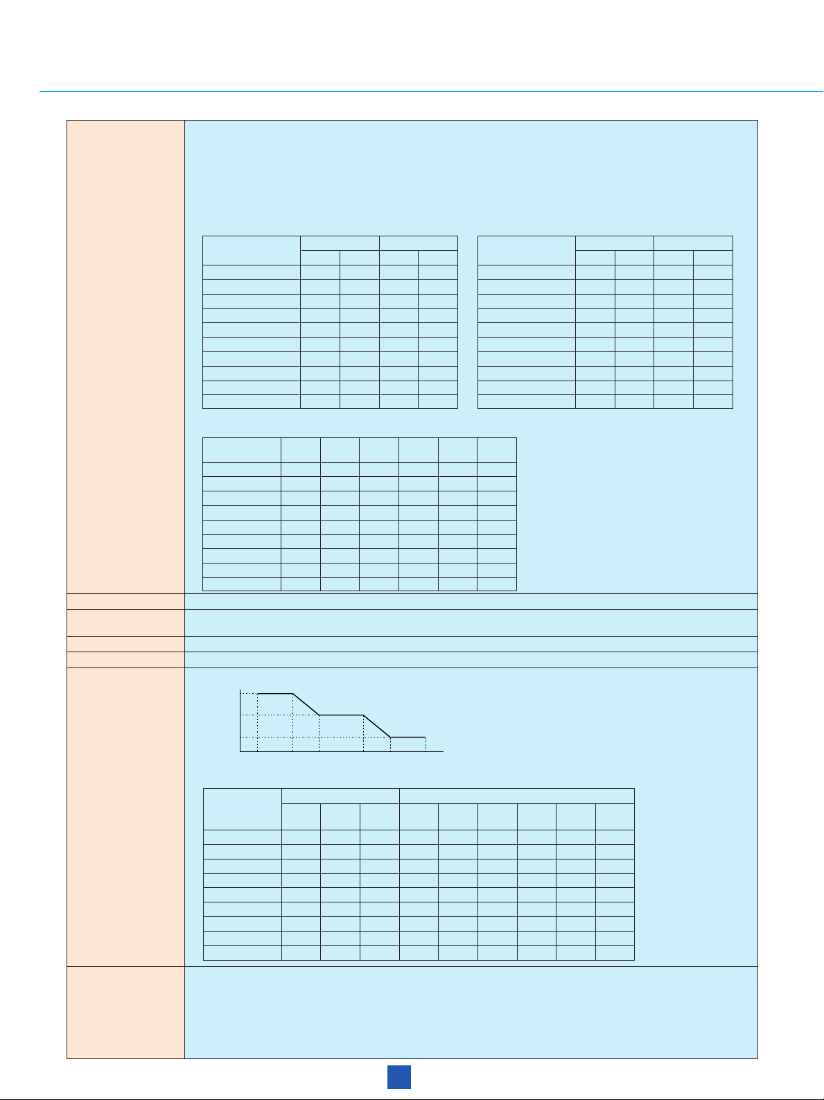
Enhanced error/alarm simulation
The MP1570A can generate normal and abnormal
frames alternately to test the frame synchronization
function of terminal equipment. (This function is an
SDH FAS error addition function.)
Pointer measurements
Pointer sequence test
by simple operation
N=1 to 15 M=0 to 15 Alternative
Frame alignment error simulation
Pointer sequence measurements
The user can select one of four through-modes:
transparent, overhead/over-write, payload/overwrite, and add/drop.
7
Page 8

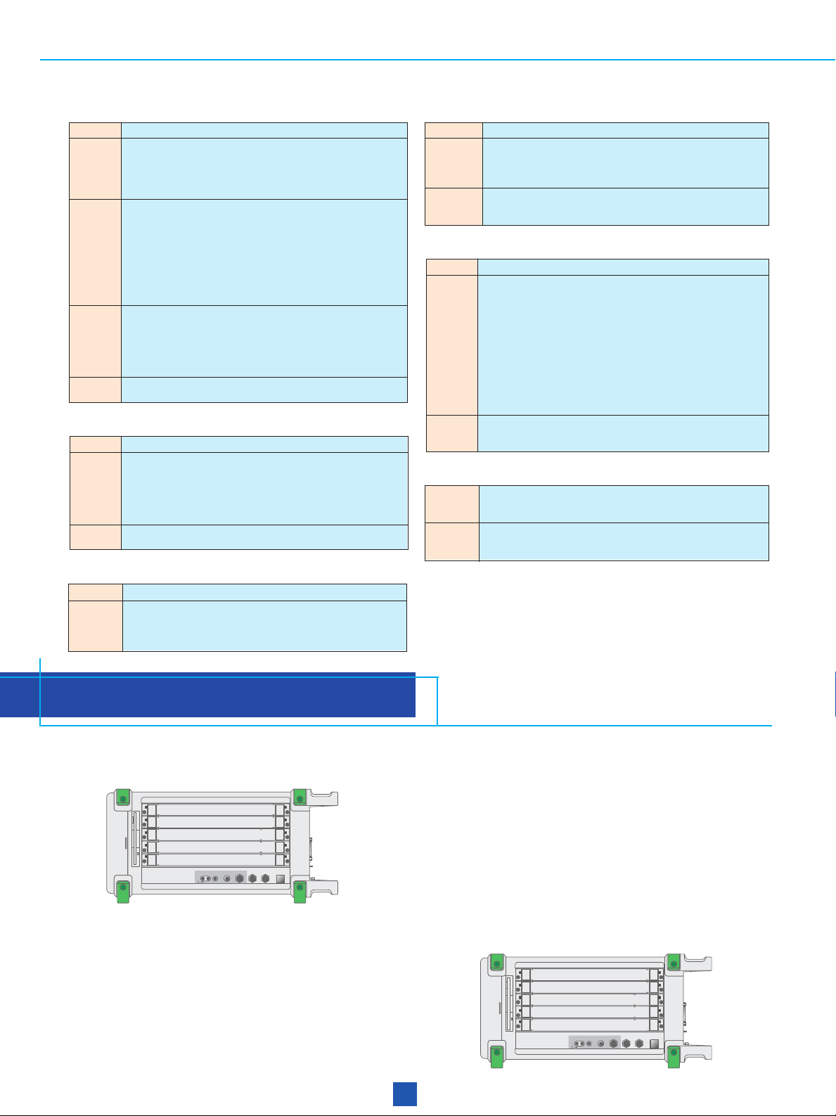
Specifications
• MP0121A 2/8/34/139/156M
Bit rate 2.048, 8.448, 34.368, 139.264 Mb/s
Level/waveform Conforms to ITU-T G.703 (with 20 dB monitoring point)
Connectors
Clock Internal (accuracy: ±7 ppm, jitter unit not installed), external (ECL [AC] 50 Ω), received signal
Frame format Framed: 2 Mb/s (with/without CRC-4 at channels 30/31, G.704), 8 Mb/s (G.742), 34 Mb/s (G.751), 139 Mb/s (G.751),
Test patterns
Error addition Timing: Single, rate (1E–3, 1E–4, 1E–5, 1E–6, 1E–7)
Alarm addition
Measurements Error performance: G.821 (inc. Annex D), M.2100, G.826
LEDs LOS, AIS, LOF, MF loss, RDI, RDI (MF), sync loss, errors
Monitor Frame word
Trouble search Auto search for errors/alarms in all measured channels
Delay measurement 0 to 1 s
Auxiliary interface Clock sync output, frame sync output, error output
1: Built-in 156M CMI (electrical) interface
*
*1Unit
BNC (75 Ω, unbalanced), 3-pin Siemens (120 Ω, balanced)
2.048 Mb/s: HDB3 (balanced/unbalanced)
8.448, 34.368 Mb/s: HDB3 (unbalanced)
139.264 Mb/s: CMI (unbalanced)
Unframed: 2, 8, 34, 139 Mb/s
MUX/DEMUX (Option 06)
11
15
20
PRBS: 2
Word: 16-bit programmable, all 0, all 1
Bit (all, test pattern), code, E-bit
FAS: n in 16 (n: 1 to 4), all
LOS, LOF, AIS, RDI, RDI (MF)
Timing: All
Mode: Single, repeat, manual
In-service
Out-of-service
– 1, 2
– 1, 2
Errors: Frame, code, CRC-4, E-bit
Alarms: Power-fail, LOS, AIS, LOF, MF loss, RDI, RDI (MF)
Errors: Frame, code, CRC-4, E-bit, bit
Alarms: Power-fail, LOS, AIS, LOF, MF loss, RDI, RDI (MF), sync loss
Error performance: G.821 (inc. Annex D), M.2100, G.826
– 1, 2
23
– 1 (O.151)
• MP0122A 1.5/45/52M
Bit rate 1.544, 44.736 Mb/s
Level/waveform
Connectors
Clock Internal (accuracy: ±7 ppm, jitter unit not installed), external (ECL [AC] 50 Ω) received signal
Frame format
Test patterns
Error addition Timing: Single, rate (1E–3, 1E–4, 1E–5, 1E–6, 1E–7)
X-bit setting 00, 01, 10, 11
Alarm addition
Measurements Error performance: G.821 (inc. Annex D), M.2100, G.826
LEDs LOS, LOF, AIS, RDI, sync loss, errors
Trouble search Auto search for errors/alarms in all measured channels
Delay measurement 0 to 1 s
Auxiliary interface Clock sync output, frame sync output, error output
1: Built-in 52M B3ZS (electrical) interface
*
2: Built-in 52M B3ZS (electrical) and optical interfaces
*
3: Mounted Option 09 (Japan Mapping)
*
*1Unit, MP0122B 1.5/45/52/52M
1.544 Mb/s: ANSI T1.102 (with 20 dB monitoring point), 0/655 ft
44.736 Mb/s: ANSI T1.102 (with 20 dB monitoring point), 0/450/900 ft
BNC (75 Ω, unbalanced), Bantam (100 Ω, balanced)
1.544 Mb/s: AMI/B8ZS (balanced), 44.736 Mb/s: B3ZS (unbalanced)
Unframed: 1.5, 45 Mb/s
Framed: 1.5 Mb/s (D4, ESF, Japan ESF
11
15
PRBS: 2
Word: 16-bit program, all 0, all 1, 3 in 24 (1.5 Mb/s)
Bit (all, test pattern), code, parity, CRC-6, C-bit, REI
FAS (45 Mb/s): n in 16 (n: 1 to 4), all
LOS, LOF, AIS, RDI
Timing: All
Mode: Single, repeat, manual
In-service
Out-of-service
– 1, 2
Errors: FAS, code, parity, CRC-6, C-bit, REI
Alarms: Power-fail, LOS, AIS, LOF, RDI
Errors: FAS, code, parity, CRC-6, C-bit, REI, bit
Alarms: Power-fail, LOS, AIS, LOF, RDI, sync loss
Error performance: G.821 (inc. Annex D), M.2100, G.826
20
– 1, 2
– 1 (zero suppress), 2
*2(1.31)Unit
*3), 45 Mb/s (M13, C-bit), MUX/DEMUX (Option 07)
20
23
– 1, 2
– 1 (O.151)
8
Page 9

• 52/156/622/2488/9953M
Bit rate 51.840, 155.520, 622.080, 2488.320, 9953.28 Mb/s
52M (electrical: B3ZS)
52M (optical): As per MP0122B unit optical interface specifications
Level/waveform 156M (optical): As per optical 156M/622M unit specifications
156M (electrical: CMI)
622M (electrical/optical): As per optical 156M/622M unit and NRZ unit specifications
2488M (electrical/optical): As per 2.5G unit and 2.5G/10G unit specifications
9953M (electrical/optical): As per 2.5G/10G unit specifications
Clock
Internal (accuracy: ±3.5 ppm, jitter unit not installed), Lock (2 MHz, 1.5 MHz, 64 kHz + 8 kHz, 2 Mb/s, 1.5 Mb/s),
external (ECL [AC] 50 Ω, 9953M: 1.02 to 0.58 Vp-p, 50 Ω), received signal
Frame SDH/SONET, CID pattern, non-frame
Mapping See Fig. 1
Through Trance parent, over head overwrite, payload overwrite, Add/Drop
11
PRBS: 2
–1, 2
Test patterns (conform to O.151)
Word: 16-bit programmable, all 0, all 1
Bit all (all, test pattern), FAS, B1, B2, B3, BIP-2, MS-REI, HP-REI, LP-REI
Error addition
Timing: Single, single (burst) bit (1 to 64000), rate (1E–3, 1E–4, 1E–5, 1E–6, 1E–7, 1E–8, 1E–9)
User program AE-B (A: 1.0 to 9.9 step 0.1, B: 2 to 10)
Alternative: alarm frame (0 to 8000), normal frame (1 to 8000)
LOS, LOF, MS-AIS, MS-RDI, AU-AIS, AU-LOP, HP-SLM, HP-TIM, HP-RDI, HP-UNEQ, TU-AIS, TU-LOP, TU-LOM, LP-SLM,
Alarm addition
LP-TIM, LP-RDI, LP-UNEQ, LP-RFI
Timing: Single, single (burst) frame
Alternative: alarm frame (0 to 8000), normal frame (1 to 8000), all
Mode: Single, repeat, manual
In-service/Out-of-service
Errors: B1, B2, B3, BIP-2, MS-REI, HP-REI, LP-REI
Measurements Alarms: Powerfail, LOS, LOF, OOF, MS-AIS, MS-RDI, AU-AIS, AU-LOP, HP-SLM, HP-TIM, HP-RDI, HP-UNEQ, TU-AIS,
TU-LOP, TU-LOM, LP-SLM, LP-TIM, LP-RDI, LP-UNEQ, LP-RFI
Error performance: G.826, M2101, M2110, M2120
Preset: Alarm measurement condition
LEDs
LOS, LOF, OOF, MS-AIS, MS-RDI, AU-AIS, AU-LOP, HP-RDI, HP-SLM, TU-AIS, TU-LOM, TU-LOP, LP-RDI, LP-RFI, LP-SLM,
Tandem, sync. loss, error
N1 byte (Type 1, Type 2), N2 byte
Tandem connection Errors: N2 BIP-2, TC-REI, OEI, IEC
Alarms: VC-AIS, ISF, FAS, HP-Incoming-AIS, HP-TC-RDI, HP-ODI, LP-Incoming-AIS, LP-TC-RDI, LP-ODI
Justification
AU pointer, TU pointer, C, C1/C2
Measurement: NDF, +PJC, –PJC, Cons. C, C1/C2
Monitor SOH, POH, K1/K2, pointer, path trace (TIM alarms detectable), Tandem, payload
Signal of opposites polarity, regular with double, regular with missing, double of opposites polarity, 87-3/26-1 (normal, add,
Pointer sequence cancel), continuous pattern (normal, add, cancel), single pointer adjustment, maximum rate pointer burst, phase transient pointer
burst, initialize period polarity, cooldown period
Over head capture SOH/POH (any 1 byte), H1/H2, K1/K2
Dummy channel setting
Simultaneous measurement
Payload: Dummy, copy, mixed payload
Setting: POH, pathtrace, SS bit, Tandem
VC2, VC12, VC11
Trouble search Auto search for errors/alarms in all measured channels
Measurement period: 0.5, 1, 2, 5, 10 s
Delay Measurement range: 0 to 999 µs, 1.0 to 999.9 ms, 1.0 to 10.0 s, Time out
Display accuracy: ±5 µs (0.5, 1 s), ±50 µs (2, 5, 10 s)
Switch time measurement
Trigger
Internal: B1, B2, B3, BIP-2, MS-REI, HP-REI, LP-REI, MS-AIS, AU-AIS, AU-LOP, HP-RDI, TU-AIS, TU-LOM, TU-LOP, LP-RDI,
APS (K1/K2)
LP-RFI, Bit
External: Measures trigger input signal (active high)
Threshold: Specify non-error alarm between 1 ms, 10 ms, 100 ms
Sequence generation: 2 to 64 word, repeat (8000 frame)
Sequence capture: 2 to 64 word, repeat(8000 frame)
Frequency measurement
Range: ±100 ppm, Accuracy: ±3.5 ppm (jitter unit not installed)
OH change: SOH/POH 1 byte, K1/K2, RSOH, MSOH, SOH, POH (except B1, B2, B3, BIP-2)
PTR 64 frame: AU pointer, TU pointer
Timing: Single, Repeat (2 to 64)
Over head test Setting: PTR, NDF, +PJC, –PJC
OH BERT: SOH/POH 1 byte (exclude B1, B2, B3, BIP-2), D1-D3, D4-D12
Test pattern: 2
OH add/drop: SOH/POH 1 byte, D1-D3, D4-D12 (exclude B1, B2, B3, BIP-2 additional type)
Japan mapping (option 09)
VC11 Signaling (8-multiframe, 64-multiframe setting)
*1: ANSI T1.102, 0/450 ft
*2: ITU-T G.703
15
20
–1, 2
–1 (zero suppress, MP0122A/B installed), 2
11
15
–1, 2
–1
20
–1, 2
23
31
–1, 2
–1 (only concatenation mapping 16C/64C)
9
Page 10

Frame memory/capture
(option 13)
Memory size: 64 frame (156M, 622M, 2.5G), 26 frame (10G)
Insert/extract Bit rate: 10G (52M, 156M), 2.5G (52M, 156M)
Payload offset ±100 ppm/0.1 ppm step
Auxiliary Clock sync output, trigger input, trigger output, DCC interface (V.11), order wire, receive clock output
1: Mounted MP0122A/B
*
2: Mounted MP0121A
*
MP0127A/0128A/0129A are usable (for specifications, refer to the MP1552B data sheet).
• General
Printer Internal, external
Internal memory Measurement settings memory: 10, graphics memory: 15
Others
EMC EN50082-1: 1992
Safety EN61010-1: 1993 (Installation Category ΙΙ, Pollution Degree ΙΙ)
Dimensions and mass 320 (W) x 177 (H) x 350 (D) mm, 10 kg approx. (excluding plug-in units and options)
Power 100 to 240 Vac, 47.5 to 63 Hz, ≤500 VA
Temperature 0˚ to +40˚C
1: The video output, RS-232C, GPIB and Ethernet options cannot all be used simultaneously.
*
Only the video output + RS-232C, or video output + GPIB, or RS-232C + GPIB board, or Ethernet board combinations support simultaneous use, so change
the board combinations according to the purpose.
FDD, RS-232C (Option 01)*1, GPIB (Option 02)*1, Ethernet (Option 03)*1, video output (Option 04)*1, buzzer, clock, help, screen copy
EN55011: 1991, Group 1, Class A
Harmonic current emissions: EN61000-3-2 (1995)
STM-64
STM-16
STM-4
STM-1
STM-0
STM-64C
STM-16C
STM-4C
STM-1C
x 4
x 16
∗
∗
x 64
4
4,∗5
AUG
x 4
AU-4 VC-4
x 3
AU-3 VC-3
x 4
x 4
VC4-64C
VC4-16C
VC4-4C
VC4
x 3
TUG-3 TU-3
x 7
x 7
1: Requires MP0121A
∗
2: Requires Japan mapping
∗
3: Requires MP0122A/B
∗
4: Requires MU150000A
∗
5: Requires MU150000A/150008A/150009A/150010A
∗
TUG-2
TU-2 VC-2
x 3
TU-12
x 4
TU-11
VC-3
VC-12
VC-11
Fig. 1 Mapping structure
1
139M (Async.)
Bulk
34M (Async.)
34M (Sync.)
45M (Async.)
Bulk
Bulk
6M (Async.)
6M (Bit sync.)
mc
2M (Async.)
2M (Bit sync. F)
2M (Bit sync. L)
2M (Byte sync. F)
2M (Byte sync. L)
Bulk
1.5M (Async.)
1.5M (Bit sync. F)
1.5M (Bit sync. L)
1.5M (Byte sync. F)
1.5M (Byte sync. L)
Bulk
384k (data)
384k (voice)
Byte (data)
Byte (voice)
Bulk
Bulk
Bulk
Bulk
∗
∗
1
1
∗
1
∗
3
∗
1
∗
∗
∗
1
∗
2
∗
2
∗
2
∗
2
∗
1
1
1
∗
1
∗
10
Page 11

• MP0124A/0125A/0126A Jitter Unit
50/200 UI range (156M/622M)
[UIp-p]
Jitter frequency
F6
50.5/202
--20 dB/dec
--20 dB/dec
--20 dB/dec
20.2
2.02
0.5
0.2
F1 F1' F2
F2'
F3
F4
F5
Jitter amplitude
20 UI
range
2 UI
range
Bit rate MP0125A: 1.544, 44.736, 51.840, 155.520, 622.080 Mb/s
MP0124A: 2.048, 8.448, 34.368, 139.264, 155.520, 622.080 Mb/s
MP0126A: 1.544, 2.048, 8.448, 34.368, 44.736, 139.264, 51.840, 155.520, 622.080 Mb/s
Modulation frequency: 0.1 Hz to 6 MHz
Amplitude: 0 to 202.0 Ulp-p
Resolution: 0.001 Ulp-p (2 Ul range), 0.01 Ulp-p (20 Ul range), 0.1 Ulp-p (50/200 Ul range)
Jitter generation
Bit rate F1 F1’ F2*F2’*F3
*
F4
*
F5
*
(Mb/s) (Hz) (Hz) (kHz) (kHz) (kHz) (kHz) (kHz) (kHz)
1.544 0.1 – 0.5 – 10 12.5 50 –
2.048 0.1 – 1 – 20 27.5 110 –
8.448 0.1 – 2 – 20 105 420 –
34.368 0.1 – 5 – 100 250 1000 –
44.736 0.1 – 5 – 100 250 1000 –
139.264 0.1 – 5 – 100 1000 4000 –
51.840 0.1 – 2 – 80 50 – 500
155.520 0.1 1000 6.5 25 500 150 – 1500
622.080 0.1 500 25 50 500 600 – 6000
: typical value
*
Accuracy (at Fr): ±5% ±0.05 Ulp-p (2 Ul range), ±5% ±0.3 Ulp-p (20 Ul range), ±5% ±0.8 Ulp-p (50 Ul range),
±5% ±3.2 Ulp-p (200 Ul range) *Fr: 100 kHz (156M/622M, 2Ul range), 500 Hz (1.5M, 20Ul range), 1 kHz (others)
Jitter tolerance Conforms to ITU-T G.823/G.824/G.825/G.958
measurement Display: Numeric, graphic
Frequency offset
Range: ±999.9 ppm/step (0.1 ppm, Jitter: off), ±70 ppm/step (0.1 ppm, Jitter: on/off)
Accuracy: ±0.1 ppm (after power-on, calibrates after 60 min. warm-up, 23˚ ±5˚C)
Auxiliary interface External modulation input, external 10 MHz reference input, reference clock output
Conforms to ITU-T O.172 [TABLE 8 (f1-f4), TABLE 9, pseudo-random signal (f1-f4) only]
Modulation frequency: 2 Hz to 5 MHz
Amplitude: 0 to 20.00 Ulp-p, 0 to 7.07 Ulrms (Option 01)
Resolution: 0.001 Ulp-p/0.001 Ulrms (2 Ul range), 0.01 Ulp-p/0.01 Ulrms (20 Ul range)
[UIp-p]
20.0
1
∗
(7.07)
2.0
1
∗
(0.707)
F6
*
Jitter measurement
Jitter amplitude
A1
F1
F1' F2
Bit rate A1 F1 F1’ F2 F3 F4 F5
(Mb/s) (UIp-p) (Hz) (Hz) (kHz) (kHz) (kHz) (kHz)
Jitter frequency
F3
F4
F5
1.544 0.5 2 20 0.2 2.5 10 40/(15)
2.048 0.5 2 20 0.45 6 25 100/(18)
8.448 0.5 2 20 0.2 10 100 400/(70)
34.368 0.5 2 20 0.5 40 500 800/(300)
44.736 0.5 2 20 3 40 200 400
139.264 0.5 2 20 0.25 50 1000 3500/(1200)
51.840 0.2 2 20 0.2 5 100 400
155.520 0.2 2 20 0.7 20 500 1300
622.080 0.2 2 20 20 200 2000 5000
1: rms; F1, F1' = 100 Hz *2: 20 Ul range in parentheses
*
11
2
*
2
*
2
*
2
*
2
*
Page 12
Accuracy
[Ulp-p]: ±5% ±W Ulp-p (Fr Hz)
156 Mb/s (optical): When input level –25 dBm max. add 0.01 Ulp-p/dB to above specifications.
622 Mb/s (optical): When input level –20 dBm max. add 0.01 Ulp-p/dB to above specifications.
[Ulrms]: ±5% ±Y Ulp-p (Fr Hz)
156 Mb/s (optical): When input level –25 dBm max. add 0.002 Ulrms/dB to above specifications.
622 Mb/s (optical): When input level –20 dBm max. add 0.002 Ulrms/dB to above specifications.
Frequency response (Fr Hz):
±5% (2 to 20 Hz), ±2% (20 Hz to 300 kHz), ±3% (300 kHz to 1 MHz), ±5% (1 to 3 MHz), ±10% (3 to 5 MHz)
fr: 100 kHz (156M/622M, 2 Ul range), 1 kHz (others)
Jitter measurement
*
Bit rate (Mb/s)
W (UIp-p)
2 UI 20 UI 2 UI 20 UI
1.544 (CLK) 0.015 0.20 0.005 0.03
1.544
(AMI/B8ZS)
0.040 0.22 0.006 0.04
2.048 (CLK) 0.015 0.20 0.005 0.03
2.048 (HDB3) 0.040 0.22 0.006 0.04
8.448 (CLK) 0.015 0.20 0.005 0.03
8.448 (HDB3) 0.040 0.22 0.006 0.04
34.368 (CLK) 0.015 0.20 0.005 0.03
34.368 (HDB3) 0.040 0.22 0.017 0.04
44.736 (CLK) 0.015 0.20 0.005 0.03
44.736 (B3ZS) 0.040 0.22 0.006 0.04
1: With HP1 + LP, *2: With HP + LP, *3: +10˚ to +40˚C
*
Filter
Bit rate HP0 HP1 HP2 HP2’ HP LP
(Mb/s) (Hz) (Hz) (kHz) (kHz) (kHz) (kHz)
1
*
Y (UIrms)
2
*
Bit rate (Mb/s)
W (UIp-p)
2 UI 20 UI 2 UI 20 UI
139.264 (CLK) 0.030 0.20 0.005 0.03
139.264 (CMI) 0.040 0.30 0.022 0.06
51.840 (CLK) 0.015 0.20 0.005 0.03
51.840 (B3ZS) 0.040 0.22 0.017 0.05
51.840 (optical)
*30.070 0.30 0.022 0.06
155.52 (CLK) 0.035 0.20 0.017 0.05
155.52 (CMI) 0.070 0.30 0.022 0.06
155.52 (optical)
*30.070 0.30 0.022 0.06
622.08 (CLK) 0.050 0.20 0.027 0.07
622.08 (optical)
*30.100 0.30 0.032 0.08
1.544 10 10 8 – 12 40
2.048 10 20 18 0.7 12 100
8.448 10 20 3 80 12 400
34.368 10 100 10 – 12 800
44.736 10 10 30 – 12 400
139.264 10 200 10 – 12 3500
51.840 10 100 20 – 12 400
155.520 10 500 65 – 12 1300
622.080 10 1000 250 – 12 5000
Hit measurement Count, seconds, % free seconds
Jitter transfer Conforms to ITU-T G.823/G.824/G.958 [selective bandwidth: ≤10 Hz (modulation frequency: ≥20 Hz)]
measurement Display: Numeric, graphic
Frequency measurement
Resolution: 0.1 ppm, Display: Hz or ppm (after power-on, calibrates after 60 min. warm-up, 23˚ ±5˚C)
Auxiliary interface Demodulation output, reference clock input
Modulation frequency: 10 µHz to 0.2 Hz (sine wave)
A0
A1
Amplitude
A2
f1f0 f2 f3 f4 f5
Frequency (Hz)
1
*
Y (UIrms)
2
*
Bit rate
Wander generation
(Mb/s)
1.544 40 – 20 10 – – 65 130 200
2.048 40 – 20 10 – – 65 130 200
8.448 200 – 20 10 – – 13 130 200
34.368 1000 113 20 10 180 1.6 23 130 200
44.736 1200 135 20 10 180 1.6 19 130 200
139.264 3000 338 50 10 180 1.6 19 130 200
51.840 1200 135 20 10 180 1.6 19 130 200
155.520 3600 406 50 10 180 1.6 16 130 200
622.080 14400 1620 200 10 180 1.6 16 130 200
Reference input: 1.544M (AMI/B8ZS, clock), 2.048M (HDB3, clock)
Measurement range
p-p: 0.0 to 3.2E5 ns, +p/–p: 0.0 to 1.6E5 ns, TIE: ±0.0 to 1.6E5 ns, MTIE
Wander measurement
(Option 02) Resolution: 0.1 ns
: MTIE, TDEV measurement require external PC and MX150001A Wander (MTIE, TDEV) Application Software
*
Sampling interval: 25 ms
Filter: DC to 0.01 Hz, DC to 10 Hz, 0.01 Hz to 10 Hz
Display: Numeric, graphic
Amplitude Frequency
A0 A1 A2 f0 f1 f2 f3 f4 f5
(UIp-p) (UIp-p) (UIp-p) (µHz) (µHz) (mHz) (mHz) (mHz) (mHz)
*
: 0.0 to 1E6 ns, TDEV*: 0.0 to 1E6 ns
12
Page 13
• MP0130A 2.5G Jitter Unit
F1 F1' F2'
F2
F3
F4
F5
[UIp-p]
808
20.2
2.02
0.5
0.2
Modulation frequency
Amplitude
800 UI
range
20 UI
range
2 UI
range
--20 dB/dec
--20 dB/dec
--20 dB/dec
Frequency: 2488.32 MHz
Modulation frequency: 0.1 Hz to 20 MHz
Amplitude: 0 to 808.0 UIp-p
Jitter generation
Bit rate
F1 F1’ F2 F2’ F3 F4 F5
(Hz) (Hz) (Hz) (kHz) (kHz) (kHz) (kHz)
2488.32 Mb/s 0.1 15 600 25 500 2,000 20,000
Jitter tolerance
measurement
Conforms to ITU-T G.825, G.958A, G.958B, user, Bellcore 253
Frequency offset ±70 ppm/step (0.1 ppm, jitter: on/off)
Auxiliary interface External clock input, reference clock output
Frequency: 2488.32 MHz ±50 ppm, conforms to ITU-T O.172 [TABLE 8 (f1-f4) only]
Jitter measurement
[UIp-p (UIrms)]
32
(11.31)
2.0
(0.707)
Amplitude
0.2
(0.0707)
Bit rate
2488.32 Mb/s
32 UI
range
2 UI
range
F0 F0' F2
Modulation frequency
F0 F0’ F2 F2’ F3 F4
(Hz) (Hz) (kHz) (kHz) (kHz) (Hz)
2 UI – 100 – 100 1,000 20,000
32 UI 10 – 6.25 – 1,000 20,000
Accuracy (Mounted MU150008A, MU150009A, MU150001A)
[Ulp-p]: ±5% ±W Ulp-p (Fr Hz)
2488 Mb/s (optical): When input level –12 to –10 dBm max. add 0.01 Ulp-p/dB to above specifications.
[Ulrms]: ±5% ±Y Ulp-p (Fr Hz)
2488 Mb/s (optical): When input level –12 to –10 dBm max. add 0.002 Ulrms/dB to above specifications.
Bit rate (Mb/s)
W (UIp-p)
2 UI 20 UI 2 UI 20 UI
1
*
2488 (CLK) 0.030 0.60 0.007 0.35
2488 (optical) 0.100 2.20 0.027 0.55
Jitter transfer
measurement
Frequency measurement
ITU-T G.958A, G.958B, user, Bellcore 253 [selectable bandwidth: ≤10 Hz (modulation frequency: ≥20 Hz)]
2488.32 MHz ±100 ppm (resolution: 0.1 ppm)
Hit measurement Count, seconds, % free seconds
Auxiliary interface Reference, clock input
Frequency: 2488.32 MHz
Modulation frequency: 10 µHz to 200 mHz (sine wave)
A0
F2'
Y (UIrms)
F3
F4
2
*
Wander generator
A1
Amplitude
A2
F5
F4
Bit rate
F2
F0 F1
Modulation frequency
F3
Amplitude (UIp-p) Frequency (mHz)
A0 A1 A2 f0 f1 f2 f3 f4 f5
2488M 57,600 6,480 800 0.01 0.18 1.6 16 130 200
13
Page 14

Wander measurement
SDH
PDH
AAL1
ATM/AAL
AAL2
AAL3/4
AAL5
ATM
STM-1c
STM-0
139M (G.832)
34M (G.832)
2M (G.704)
45M (G.704)
1.5M (G.704)
STM-4c (optical)
STM-1c (optical)
• MP0123A ATM Unit
Bit rate 1.544, 2.048, 34.368, 44.736, 139.364, 51.840, 155.520, 622.080 Mb/s
Mapping
Traffic pattern CBR, burst, sawtooth, PCR with CBR, Poisson
Test patterns
Error addition
Alarm addition LCD, VP/VC AIS, VP/VC RDI, VP/VC CC, VP/VC loopback cell
PM cell Error insertion: Lost cell, misinserted cell, BIPV, SECB
Cell editing O.191, AAL1, AAL2, AAL3/4, AAL5, AIS, RDI, CC, loopback, FM, BR, background (10 ch)
Memorized cell Possible to send after editing receiver's capture data
Measurement mismatch, BA size, AL, length, undeliverded PDU (one of CPI error, B/E tag mismatch, BA size error, AL error, or
LED LCD, VP-AIS, VP-RDI, VP-LOC, VC-AIS, VC-RDI, VC-LOC, error
Monitor Live monitor (1023 channel monitor), traffic monitor, cell monitor
Delay measurement 1-point CDV, 2-point CDV
Capture 1 to 2016 cells
Frequency:
2488.32 MHz ±50 ppm (Wander measurement becomes effective when MP0124A/0125A/0126A plus Option 02 is mounted.)
Measurement frequency: Up to 10 Hz
Measurement range
P-P: 0.0 to 3.2E5 ns, +P/–P: 0.0 to 1.6E5 ns, TIE: 0.0 to ±1.6E5 ns, MTIE/TDEV: 0.0 to 1.0E6 ns
Auto-measurement: TIE, MTIE, TDEV (MTIE, TDEV: necessary for MX150001A application software)
Cell: Single cell PRBS 9, cross cell PRBS 9/15/23, 16-bit word pattern, edit pattern, time stamp
O.191: Edit pattern
AAL1: Single cell PRBS 9, cross cell PRBS 9/15/23, 16-bit word pattern, edit pattern, time stamp
AAL2 (CPS-PDU): Time stamp
AAL2 (CPS-PACKET): Single cell PRBS 7, 8-bit word pattern, edit pattern
AAL3/4 (SAR-PDU): Time stamp
AAL3/4 (CPCS-PDU): Single cell PRBS 9, cross cell PRBS 9/15/23, 16-bit word pattern, edit pattern
AAL5: Single cell PRBS 9, cross cell PRBS 9/15/23, 16-bit word pattern, edit pattern
Cell: HEC, programmable pattern
O.191: Lost cell, misinserted cell, errored cell, SECB
AAL1: Lost cell, SNP, PRBS, word
AAL2 (CPS-PDU): P, SN, OSF
AAL2 (CPS-PACKET): HEC, PRBS, word
AAL3/4 (SAR-PDU): SN, CRC10, segment type, LI, abort
AAL3/4 (CPCS-PDU): CPI, B/E tag mismatch, BA size, AL, length, PRBS, word
AAL5: Frame size, length, CRC32, abort, PRBS, word
Mode: Single, repeat, manual
Error
Cell: Cell count, correctable HEC, uncorrectable HEC, non-conforming cell
O.191: Errored cell, lost cell, misinserted cell, SECB
AAL1: SAR-PDU count, lost cell, SNP, uncorrectable SNP, PRBS, word
AAL2: CPS-PDU count, P, OSF, SN, CPS packet count, HEC, PRBS, word
*
: SAR-PDU count, CRC10, MID count (SAR-PDU with selected MID value), SN, ST (segment type), LI, abort, discarded
AAL3/4
AAL5: CPCS-PDU count, frame size, length, CRC32, abort, discarded PDU (one of frame size error, length error, CRC32 error, or
PDU (one of SN error, Ll error, abort, COM with ST error, or EOM with ST error), CPCS-PDU count, CPI, B/E tag
length error), PRBS, word
CRC10 is calculated for all SAR-PDU. The others are calculated for SAR-PDU with specified MID.
*
abort), PRBS, word
FM: Lost cell, misinserted cell, BIPV, SECB
BR: Lost cell, misinserted cell, BIPV, SECB
Alarm: LCD, VP/VC segment AIS, VP/VC end-to-end AIS, VP/VC segment RDI, VP/VC end-to-end RDI, VP/VC segment LOC,
VP/VC end-to-end LOC
14
Page 15

• MP0131A Add/Drop Unit
Bit rate 1.544, 2.048, 34.368, 44.736, 139.264 Mb/s
Level/waveform 44.736 Mb/s: ANSI T1.102, 0/450/900 ft (0 ft: Drop only)
Connector 3-pin Siemens (120 Ω, balanced): 2.048 Mb/s (HDB3)
Mapping See Fig. 2
1.544 Mb/s: ANSI T1.102, 0/655 ft
2.048/34.368/139 Mb/s: ITU-T G.703
BANTAM (100 Ω, balanced): 1.544 Mb/s (AMI/B8ZS)
BNC (75 Ω, unbalanced): 2.048 Mb/s, 34.368 Mb/s (HDB3), 139.264 Mb/s (CMI)
STM-64
STM-16
STM-4
STM-1
STM-0
x 4
x 16
x 64
AUG
AU-4
x 3
AU-3
Fig. 2 Add/Drop mapping structure
• MP0111A Optical 156M/622M (1.31) Unit
Bit rate: 155.520, 622.080 Mb/s (NRZ)
Transmit Output level: –11.5 dBm ±3.5 dB
Receive BER 10
Wavelength: 1310 nm
Optical safety: IEC 825-1 Class 1, 21CFR1040.10 Class Ι
Connector: FC-PC (SM-F)
Bit rate: 155.520, 622.080 Mb/s (NRZ)
Sensitivity
156M: –33 to –8 dBm (test pattern: PRBS 2
622M: –28 to –8 dBm (test pattern: PRBS 2
BER 10
–10
, +10˚ to +40˚C)
–10
, +10˚ to +40˚C)
Connector: FC-PC (SM-F)
Power measurement
Measurement range: –30 to 0 dBm (peak power)
Accuracy: ≤±1 dB (–20 dBm)
Linearity: ≤±1 dB (–30 to 0 dBm)
VC-4
VC-3
x 3
TUG-3 TU-3 VC-3
x 7
x 7
TUG-2
x 3
x 4
• MP0113A Optical 156M/622M (1.31/1.55) Unit
Transmit
23
– 1,
23
– 1,
Receive BER 10
139M (Async.)
34M (Async.)
45M (Async.)
TU-12
TU-11 VC-11
VC-12
2M (Async.)
1.5M (Async.)
Bit rate: 155.520, 622.080 Mb/s (NRZ)
Wavelength: 1310/1550 nm
Output level
1.31 µm: –11.5 dBm ±3.5 dB, 1.55 µm: –5 dBm ±2 dB
Optical safety: IEC825-1 Class 1, 21CFR1040.10 Class Ι
Connector: FC-PC (SM-F)
Bit rate: 155.520, 622.080 Mb/s (NRZ)
Sensitivity
156M: –33 to –8 dBm (test pattern: PRBS 2
622M: –28 to –8 dBm (test pattern: PRBS 2
BER 10
–10
, +10˚ to +40˚C)
–10
, +10˚ to +40˚C)
23
23
– 1,
– 1,
Connector: FC-PC (SM-F)
Power measurement
Measurement range: –30 to 0 dBm (peak power)
Accuracy: ≤±1 dB (–20 dBm)
Linearity: ≤±1 dB (–30 to 0 dBm)
• MP0112A Optical 156M/622M (1.55) Unit
Bit rate: 155.520, 622.080 Mb/s (NRZ)
Transmit Output level: –5 dBm ±2 dB
Receive BER 10
Wavelength: 1550 nm
Optical safety: IEC825-1 Class 1, 21CFR1040.10 Class Ι
Connector: FC-PC (SM-F)
Bit rate: 155.520, 622.080 Mb/s (NRZ)
Sensitivity
156M: –33 to –8 dBm (test pattern: PRBS 2
622M: –28 to –8 dBm (test pattern: PRBS 2
BER 10
–10
, +10˚ to +40˚C)
–10
, +10˚ to +40˚C)
Connector: FC-PC (SM-F)
Power measurement
Measurement range: –30 to 0 dBm (peak power)
Accuracy: ≤±1 dB (–20 dBm)
Linearity: ≤±1 dB (–30 to 0 dBm)
23
23
– 1,
– 1,
• MP0122B 1.5/45/52/52 (1.31) Unit
Optical interface
Bit rate: 51.84 Mb/s (NRZ)
Transmit Output level: –11.5 dBm ±3.5 dB
Receive Power measurement
Wavelength: 1310 nm
Optical safety: IEC 825-1 Class 1, 21CFR1040.10 Class Ι
Connector: FC-PC (SM-F)
Bit rate: 51.84 Mb/s (NRZ)
Sensitivity
52M: –33 to –8 dBm (test pattern: PRBS 2
+10˚ to +40˚C)
Connector:FC-PC (SM-F)
Measurement range: –30 to 0 dBm (peak power)
Accuracy: ≤±1 dB (–20 dBm)
Linearity: ≤±1 dB (–30 to 0 dBm)
Monitor input
Level: 0.1 to 1.0 Vp-p (AC), Connector: SMA (50 Ω)
15
23
– 1, BER 10
–10
,
Page 16
• MU150008A/150009A/150010A 2.5G unit
Trigger Output Orderwire
Trigger Input
DCS Input
75Ω75Ω75Ω100Ω120Ω
Slot1
Slot2
Slot3
Slot4
Slot5
Trigger Output Orderwire
Trigger Input
DCS Input
75Ω75Ω75Ω100Ω120Ω
Slot1
Slot2
Slot3
Slot4
Slot5
Bit rate 2488.32 Mb/s (NRZ)
Wavelength: 1310 nm (MU150008A), 1550 nm (MU150009A),
Optical
output
Output level: –4 dBm ±3 dB
Optical safety: IEC825-1 Class 3A, 21CFR1040.10 Class ΙΙΙb
Connector: FC-PC (SM-F)
Sensitivity
Narrow: –28 to –9 dBm (BER 10
Wide: –20 to –9 dBm (BER 10
1310/1550 nm (MU150010A)
–27 to –9 dBm (BER 10
–10
, +10˚ to +40˚C)
–10
, +10˚ to +30˚C),
–10
, 0˚ to +30˚C)
Optical Connector: FC-PC (SM-F)
input Power measurement
Range: –30 to –9 dBm (peak power)
Accuracy: ≤±2 dB (–20 dBm)
Linearity: ≤±2 dB (–30 to –9 dBm)
Transmit (NRZ)
Level: ECL (–2 V), Connector (data, clock): SMA (50 Ω)
Electrical Receive (NRZ)
I/O Level: ECL (–2 V), Connector (data, clock): SMA (50 Ω)
Monitor input
Level: 0.1 to 1.0 Vp-p (AC), Connector (data): SMA (50 Ω)
Auxiliary
interface
External clock input, receive clock output, sync. output
• MU150000A 2.5G/10G unit
Bit rate 2488.320, 9953.28 Mb/s (NRZ)
Transmit (NRZ)
Level: 0/–1 V ±0.3 V
Electrical Connector (data, clock): SMA (50 Ω)
I/O Receive (NRZ)
Level: 1 V(p-p) ±0.3 V
Connector (data, clock): SMA (50 Ω)
Auxiliary External clock input, Internal clock output, receive clock output,
interface 156M sync output, Error output
• MP0105A CMI Unit
Transmit Bit rate: 155.520 Mb/s, Level: 1 ±0.1 V, Connector: BNC (75 Ω)
Bit rate: 155.520 Mb/s
Receive
Level: 1 ±0.1 V (0 to 12 dB, with √_f auto correction and
monitor function)
Connector: BNC (75 Ω)
• MU150001A/B Optical 10G Tx (1.55)
Bit rate 9953.28 Mbit/s, 2488.320 Mb/s (Option 01, 02, 03)
Wavelength: 1550 nm band, 1310 nm band (Option 01, 03)
Optical Output level: –4 dBm ±3 dB
output Optical safety: IEC825-1 Class 3A, 21CFR1040.10 Class ΙΙΙb
Connector: FC-PC (SMF)
Electrical
input
Data input: 0/–1 ±0.3 V
Clock input: 0/–1 ±0.3 V
Connector: SMA 50 Ω
• MU150002A Optical 10G Rx (Narrow)
Bit rate 9953.28 Mbit/s, 2488.320 Mb/s (Option 01)
Sensitivity
10G: –13 to –3 dBm (BER 10
2.5G: –29 to –10 dBm (BER 10
PRBS: 2
PRBS: 2
31
–1)
23
–1) (Option 01)
–12
, NRZ, mark ratio 1/2,
–11
, NRZ, mark ratio 1/2,
Optical Connector: FC-PC (SMF)
input Power measurement
Range: –16 to 0 dBm (10G, average power),
–30 to –10 dBm (2.5G, average power)
Accuracy: ≤±2 dB (10G, –10 dBm), ≤±2 dB (2.5G, –20 dBm)
Linearity: ≤±2 dB (10G, –16 to 0 dBm),
≤±2 dB (2.5G, –30 to –10 dBm)
Electrical
output
Data output: 1 ±0.3 V(p-p)
Clock output: 0.8±0.2 V(p-p) (10G),1 ±0.3 V(p-p) (2.5G)
Connector: SMA 50 Ω
• MP0108A NRZ Unit
Transmit Level: ECL
Receive Level: ECL (–2 V)
Bit rate: 155.520, 622.080 Mb/s
Connector (clock, data): SMA (50 Ω)
Bit rate: 155.520, 622.080 Mb/s
Connector (clock, data): SMA (50 Ω)
Typical Configuration
10G b/s Configuration
•10 G (North America)
MP1570A Main frame
Slot1:MP0122A 1.5/45/52M Unit
Slot2:MU150002A Optical 10G Rx(Narrow) Unit
Slot3:MU150001A Optical 10G Tx(1.55) Unit
Slot4/5:MU150000A 2.5G/10G Unit
Front:MP0113A Optical 156M/622M(1.31/1.55) Unit
•10G (Europe)
MP1570A Main frame
Slot1:MP0121A 2/8/34/139/156M Unit
Slot2:MU150002A Optical 10G Rx(Narrow) Unit
Slot3:MU150001A Optical 10G Tx(1.55) Unit
Slot4/5:MU150000A 2.5G/10G Unit
Front:MP0113A Optical 156M/622M(1.31/1.55) Unit
16
Page 17

Trigger Output Orderwire
Trigger Input
DCS Input
75Ω75Ω75Ω100Ω120Ω
Slot1
Slot2
Slot3
Slot4
Slot5
2.5G b/s Configuration
Trigger Output Orderwire
Trigger Input
DCS Input
75Ω75Ω75Ω100Ω120Ω
Slot1
Slot2
Slot3
Slot4
Slot5
•2.5G (North America)
MP1570A Main frame
Slot1:MP0122A 1.5/45/52M Unit
Slot2: MU150009A 2.5G(1.55) Unit
Slot3:
Slot4/5:
Front:MP0113A Optical 156M/622M(1.31/1.55) Unit
2.5G b/s Configuration Jitter measurement
Slot1
Slot2
Slot3
Slot4
Slot5
DCS Input
Trigger Output Orderwire
Trigger Input
75Ω75Ω75Ω100Ω120Ω
•2.5G (Europe)
MP1570A Main frame
Slot1:MP0121A 2/8/34/139/156M Unit
Slot2:MU150009A 2.5G(1.55) Unit
Slot3:
Slot4/5:
Front:MP0113A Optical 156M/622M(1.31/1.55) Unit
Slot1
Slot2
Slot3
Slot4
Slot5
DCS Input
Trigger Output Orderwire
Trigger Input
75Ω75Ω75Ω100Ω120Ω
•2.5G (Europe)
MP1570A Main frame
Slot1:MP0121A 2/8/34/139/156M Unit
Slot2: MU150010A 2.5G(1.31/1.55) Unit
Slot3: MP0130A 2.5G Jitter Unit
Slot4/5:MP0124A 2/8/34/139M 156 /622M Unit
Front:MP0113A Optical 156M/622M(1.31/1.55) Unit
•
2.5G (North America)
MP1570A Main frame
Slot1:MP0122A 1.5/45/52M Unit
Slot2: MU150010A 2.5G(1.31/1.55) Unit
Slot3: MP0130A 2.5G Jitter Unit
Slot4/5:MP0125A 1.5/45/52M 156/622M Jitter Unit
Front:MP0113A Optical 156M/622M(1.31/1.55) Unit
Unit Slot 1 Slot 2 Slot 3 Slot 4/5
MP0121A 2/8/34/139/156M Unit
MP0122A 1.5/45/52M Unit
MP0122B 1.5/45/52/52M (1.31) Unit
MP0123A ATM Unit
MP0124A 2/8/34/139M, 156/622M Jitter Unit
MP0125A 1.5/45/52M, 156/622M Jitter Unit
MP0126A 2/8/34/139M, 1.5/45/52M,
156M/622M Jitter Unit
MU150008A 2.5G (1.31) Unit
MU150009A 2.5G (1.55) Unit
MU150010A 2.5G (1.31/1.55) Unit
MP0130A 2.5G Jitter Unit
MP0131A Add/Drop Unit
MU150000A 2.5G/10G Unit
MU150001A/B Optical 10G Tx (1.55) Unit
MU150002A Optical 10G Rx (Narrow) Unit
17
√
√√
√√
√
√
√
√
√
√
√
√
√√
√
√
√
Page 18

Ordering Information
Please specify the model/order number and quantity when ordering.
Model/Order No. Name Remarks
MP1570A SONET/SDH/PDH/ATM Analyzer
Z0169 Printer paper (5 rolls/pack): 1 pack
F0079 Fuse, 10 A: 2 pcs
B0329G Protective cover: 1 pc
J0907Q Remote interlock cord: 1 pc For MU150001A/B, MU150008A, MU150009A, MU150010A
J0908 Remote interlock terminator: 1 pc For MU150001A/B, MU150008A, MU150009A, MU150010A
E0008A Optical output control key: 1 pc For MU150001A/B, MU150008A, MU150009A, MU150010A
J0747B Fixed optical attenuator (10 dB): 1 pc For MU150001A/B
J0747C Fixed optical attenuator (15 dB): 1 pc For MU150008A/MU150009A/MU150010A
J0900A Coaxial cable (AA-165-200), 20 cm: 2 pcs For MP0130A
W1719AE MP1570A operation manual (Vol. 1 Basic operation for SDH): 1 copy
W1720AE
W1721AE MP1570A operation manual (Vol. 2 Remote control): 1 copy
W1722AE MP1570A operation manual (Vol. 3 ATM measurement): 1 copy
W1723AE MP1570A operation manual (Vol. 4 2.5G/10G measurement): 1 copy
W1724AE MP1570A operation manual (Vol. 5 Add/Drop function): 1 copy
W1725AE
W1726AE
W1323AE MX150001A wander (MTIE, TDEV) application software Supplied with MX150001A
J1002A Semi-rigid cable: 2 pcs For MU150001A/B
J1002B Semi-rigid cable: 2 pcs For MU150002A
J1002C Semi-rigid cable: 3 pcs For MU150000A
MP0121A 2/8/34/139/156M Unit
MP0122A 1.5/45/52M Unit
MP0122B
MP0123A ATM Unit
2
*
MP0124A 2/8/34/139M, 156/622M Jitter Unit Only jitter generation/measurement, requires MP0121A
MP0125A 1.5/45/52M, 156/622M Jitter Unit Only jitter generation/measurement, requires MP0122A/B
MP0126A 2/8/34/139M, 1.5/45/52M, 156/622M Jitter Unit Only jitter generation/measurement, requires MP0121A or
MU150008A
MU150009A
MU150010A
*
*
*
MP0130A 2.5G Jitter Unit Only jitter generation/measurement, requires MU150008A,
MP0131A Add/Drop Unit
MU150000A 2.5G/10G Unit
MU150001A
MU150001B
MU150002A
MP0111A
MP0112A
MP0113A
*
*
*
2
*
2
*
2
*
MP0105A CMI Unit
MP0108A NRZ Unit
MP1570A-01 RS-232C
MP1570A-02 GPIB
MP1570A-03 Ethernet
MP1570A-04
MP1570A-06 MUX/DEMUX (2/8/34/139 Mb/s) For MP0121A
*
MP1570A-07 MUX/DEMUX (1.5/45 Mb/s) For MP0122A/B
MP1570A-08 45M-2M MUX/DEMUX Requires MP0121A and MP0122A/B
MP1570A-09 Japan mapping Requires MP0122A or MP0122B
MP1570A-10
MP1570A-11
*
*
MP1570A-13 Frame memory capture (156M/622M)
MP0124A-01 RMS measurement
MP0125A-01 RMS measurement
MP0126A-01 RMS measurement
MP0130A-01 RMS measurement
MP0124A-02 Wander measurement
MP0125A-02 Wander measurement
MP0126A-02 Wander measurement
MU150008A-01 Frame memory capture (2.5G)
MU150009A-01 Frame memory capture (2.5G)
MU150010A-01 Frame memory capture (2.5G)
MU150000A-01 Frame memory capture (2.5G/10G)
MU150001A/B-01 2.5G (1.31)
MU150001A/B-02 2.5G (1.55)
MU150001A/B-03 2.5G (1.31/1.55)
MU150002A-01 2.5G
Main frame
Standard accessories
AC power cord: 1 pc
MP1570A operation manual (Vol. 1 Basic operation for SONET):
MP1570A operation manual (Vol. 6 Jitter/wander measurement):
MP1570A operation manual (Vol. 7 2.5G jitter/wander measurement):
1 copy
1 copy
1 copy
operation manual: 1 copy
Plug-in units
1.5/45/52/52M (1.31) Unit
2
2.5G (1.31) Unit With optical power meter
2
2.5G (1.55) Unit With optical power meter
2
2.5G (1.31/1.55) Unit With optical power meter
MP0122A/B
MU150009A, or MU150010A
2
Optical 10G Tx (1.55) Unit
2
Optical 10G Tx (1.55) Unit
2
Optical 10G Rx (Narrow) Unit With optical power meter
Optical 156M/622M (1.31) Unit With optical power meter
Optical 156M/622M (1.55) Unit With optical power meter
Optical 156M/622M (1.33/1.55) Unit With optical power meter, 1.31/1.55 switchable
Options
3
VGA output
1
SDH
1
SONET
18
Page 19

Model/Order No. Name Remarks
MP0111A/0112A-37
MP0111A/0112A-38
MP0111A/0112A-39
MP0111A/0112A-40
MP0111A/0112A-43
MP0113A-37 FC connector Exchangeable 3 sets
MP0113A-38 ST connector Exchangeable 3 sets
MP0113A-39 DIN connector Exchangeable 3 sets
MP0113A-40 SC connector Exchangeable 3 sets
MP0113A-43 HMS-10/A connector Exchangeable 3 sets
MP0122B-37 FC connector Replaceable, 2 sets
MP0122B-38 ST connector Replaceable, 2 sets
MP0122B-39 DIN connector Replaceable, 2 sets
MP0122B-40 SC connector Replaceable, 2 sets
MP0122B-43 HMS-10/A connector Replaceable, 2 sets
MU150008A-37 FC connector Replaceable, 2 sets
MU150008A-38 ST connector Replaceable, 2 sets
MU150008A-39 DIN connector Replaceable, 2 sets
MU150008A-40 SC connector Replaceable, 2 sets
MU150008A-43 HMS-10/A connector Replaceable, 2 sets
MU150009A-37 FC connector Replaceable, 2 sets
MU150009A-38 ST connector Replaceable, 2 sets
MU150009A-39 DIN connector Replaceable, 2 sets
MU150009A-40 SC connector Replaceable, 2 sets
MU150010A-43 HMS-10/A connector Replaceable, 2 sets
MU150010A-37 FC connector Replaceable, 2 sets
MU150010A-38 ST connector Replaceable, 2 sets
MU150010A-39 DIN connector Replaceable, 2 sets
MU150010A-40 SC connector Replaceable, 2 sets
MU150010A-43 HMS-10/A connector Replaceable, 2 sets
MU150001A/B-37 FC connector Replaceable, 2 sets
MU150001A/B-38 ST connector Replaceable, 2 sets
MU150001A/B-39 DIN connector Replaceable, 2 sets
MU150001A/B-40 SC connector Replaceable, 2 sets
MU150001A/B-43 HMS-10/A connector Replaceable, 2 sets
MU150002A-37 FC connector Replaceable, 2 sets
MU150002A-38 ST connector Replaceable, 2 sets
MU150002A-39 DIN connector Replaceable, 2 sets
MU150002A-40 SC connector Replaceable, 2 sets
MU150002A-43 HMS-10/A connector Replaceable, 2 sets
MP1777A 10 GHz Jitter Analyzer
MP9766A E/O, O/E Converter
MX150001A Wander (MTIE, TDEV) Measurement Application Software For MP0124A/0125A/0126A-02
J0796A ST connector Exchangeable, with protective caps, 1 set
J0796B DIN connector Exchangeable, with protective caps, 1 set
J0796C SC connector Exchangeable, with protective caps, 1 set
J0796D HMS-10/A connector Exchangeable, with protective caps, 1 set
J0796E FC connector Exchangeable, with protective caps, 1 set
J0162A Balanced cable, 1 m Siemens 3p-Siemens 3p
J0162B Balanced cable, 2 m Siemens 3p-Siemens 3p
J0845A Balanced cable, 6 ft BANTAM 3P/BANTAM 3P
J0775D Coaxial cable (BNC-P620 • 3C-2WS • BNC-P620, 75 Ω), 2 m
J0776D Coaxial cable (BNC-P-3W • 3D-2W • BNC-P-3W, 50 Ω), 2 m
J0398A Conversion cable (M-1PS • BANTAM 3P), 1 m
J0398B Conversion cable (M-1PS • BANTAM 3P), 2 m
J0635A Optical fiber cable, 1 m SM, FC-SPC connector both ends
J0635B Optical fiber cable, 2 m SM, FC-SPC connector both ends
J0635C Optical fiber cable, 3 m SM, FC-SPC connector both ends
J0747B Fixed optical attenuator (10 dB)
J0747C Fixed optical attenuator (15 dB)
J0747D Fixed optical attenuator (20 dB)
J0322B Coaxial cable (11SMA • SUCOFLEX104 • 11SMA), 1 m
J0008 GPIB cable, 2 m
B0448 Soft case
B0336C Carrying case
1: Must specify SDH (option 10) or SONET (option 11) when ordering depends on your system. The option price is included in the MP1570A.
*
These two options can be installed simultaneously. But in this case, one option price is charged.
2: Specify the connector to be supplied as the standard connector when ordering the above options.
*
If the connector is not specified the FC connector is supplied as standard.
3: The video output, RS-232C, GPIB and Ethernet options cannot all be used simultaneously.
*
Only the video output + RS-232C, or video output + GPIB, or RS-232C + GPIB board, or Ethernet board combinations support simultaneous use, so
change the board combinations according to the purpose.
FC connector Exchangeable 2 sets
ST connector Exchangeable 2 sets
DIN connector Exchangeable 2 sets
SC connector Exchangeable 2 sets
HMS-10/A connector Exchangeable 2 sets
Application equipment
Optional accessories
19
Page 20

ANRITSU CORPORATION
5-10-27, Minamiazabu, Minato-ku, Tokyo 106-8570, Japan
Phone: +81-3 - 3446 - 1111
Telex: J34372
Fax: +81- 3- 3442 - 0235
Overseas Subsidiaries
•
U.S.A.
ANRITSU COMPANY
North American Region Headquarters
1155 East Collins Blvd., Richardson, Tx 75081, U.S.A.
Phone: +1- 972 - 644 - 1777
Fax: +1- 972- 644 - 3416
•
Canada
ANRITSU ELECTRONICS LTD.
Unit 102, 215 Stafford Road West
Nepean, Ontario K2H 9C1, Canada
Phone: +1- 613 - 828 -4090
Fax: +1- 613- 828 - 5400
•
Brasil
ANRITSU ELETRÔNICA LTDA.
Praia de Botafogo 440, Sala 2401 CEP 22250-040,
Rio de Janeiro, RJ, Brasil
Phone: +55-21 - 5276922
Fax: +55- 21- 537 - 1456
•
U.K.
ANRITSU LTD.
200 Capability Green, Luton, Bedfordshire LU1 3LU, U.K.
Phone: +44-1582 - 433200
Fax: +44- 1582 -731303
•
Germany
ANRITSU GmbH
Grafenberger Allee 54-56, 40237 Düsseldorf 1,
Germany
Phone: +49-211- 96855 - 0
Fax: +49- 211-96855 - 55
•
France
ANRITSU S.A.
9, Avenue du Québec Z.A. de Courtabœuf 91951 Les
Ulis Cedex, France
Phone: +33-1 - 60 - 92 - 15 - 50
Fax: +33- 1 - 64 -4 6- 10 - 65
•
Italy
ANRITSU S.p.A.
Via Elio Vittorini, 129, 00144 Roma EUR, Italy
Phone: +39-06 - 502 - 26 - 66
Fax: +39- 06- 502 - 24 - 25
•
Sweden
ANRITSU AB
Botvid Center, Fittja Backe 1-3 145 84 Stockholm,
Sweden
Phone: +46-853470700
Fax: +46- 853470730
•
Singapore
ANRITSU PTE LTD.
6, New Industrial Rd., #06-01/02, Hoe Huat Industrial
Building, Singapore 536199
Phone: +65-282 - 2400
Fax: +65- 282 -2533
•
Hong Kong
ANRITSU COMPANY LTD.
Suite 719, 7/F., Chinachem Golden Plaza, 77 Mody
Road, Tsimshatsui East, Kowloon, Hong Kong, China
Phone: +852-2301 - 4980
Fax: +852-2301 - 3545
•
Korea
ANRITSU CORPORATION
14F Hyun Juk Bldg. 832-41, Yeoksam-dong,
Kangnam-ku, Seoul, Korea
Phone: +82-2 - 553 - 6603
Fax: +82- 2 - 553 - 6604
˜
5
•
Australia
ANRITSU PTY LTD.
Unit 3/170 Forster Road Mt. Waverley, Victoria, 3149,
Australia
Phone: +61-3 - 9558 - 8177
Fax: +61- 3- 9558 - 8255
•
Taiwan
ANRITSU COMPANY INC.
6F, 96, Sec. 3, Chien Kou North Rd. Taipei, Taiwan,
R.O.C.
Phone: +886-2 - 2515 - 6050
Fax: +886-2 - 2509 - 5519
Specifications are subject to change without notice.
Catalog No. MP1570A-E-A -3-(2.00) Printed in Japan 2000-1 50AGKD
 Loading...