

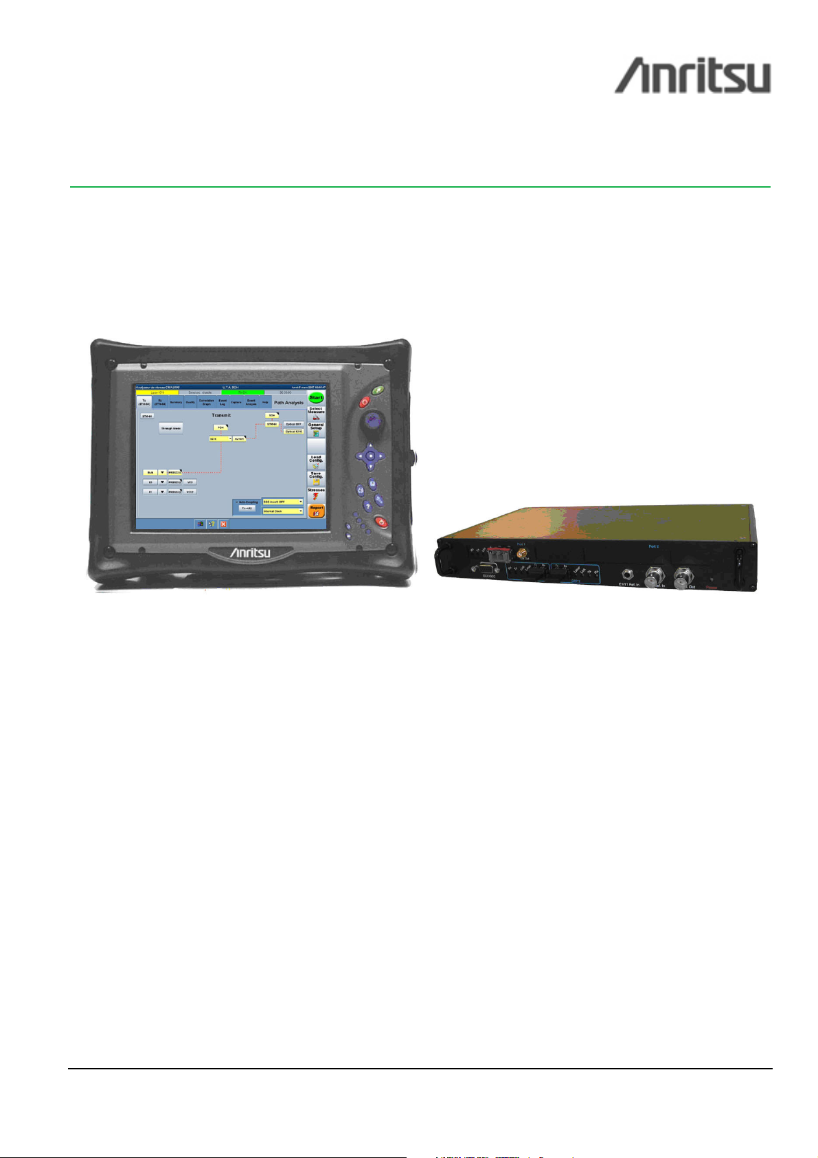
CMA 5000 - UTA SPECIFICATIONS
Universal Transport Analysis Module / SDH/SONET Application
Content
• The perfect tool for testing SDH & SONET core networks up to 10 Gbps
• Testing APS switch time reaction of the network with 125 µs resolution
• Auto-discovery of the signal structure
• Field exchangeable XFP and SFP
• Fast and professional reports
The perfect tool for testing SDH & SONET core networks up to 10 Gbps
SDH and SONET technologies are firmly established in the core and metropolitan networks. STM-64 and OC-192 are widely
deployed in today’s networks. While great care is devoted to warrant a very high quality of transport, in the real world of dayto-day installation, commissioning and maintenance activities things are not always running smooth. To this effect, several
important tests are always carried out in order to assess the good behaviour of these networks before turn-up. Similarly, when
the network has been turned on, it is paramount to keep monitoring the network health at physical level and beyond.
The SDH/SONET application of the UTA module provides a complete set of test functions for testing SDH/SONET networks
up to 10 Gbps, among which we find the checking & monitoring of the optical levels, alarm, error & frequency stressing,
tributary mapping checking, routing, connectivity and pointer tests on the synchronous payloads, round trip delay measurement,
BER tests, automatic protection scheme switching time and more.
As a part of the UTA applications family, the SDH/SONET application is just one test solution among many others. The UTA
module has been designed to support almost all the transport standards of modern networks (ex: 10 GigE, G.709, …) and
represents a new class of tester for the field engineers. One tool is all you need!
ISO 9001:2000 certified. ICMA5KUTASTM64-SPEC05-0806-A4. ©2008 Anritsu. All Rights Reserved.
Page 1 of 14
•
Key Features Key Applications
SDH/SONET interfaces up to 10 Gbps
Pluggable XFP & SFP – 1310 nm / 1550 nm
Generates and analyzes SONET/SDH frames down to the
tributary level (DS1/E1)
Automatic Protection Switching time measurement
o 125 µs measurement accuracy
Quality assessment as per G.82X and M.21XX
recommendations
Round Trip Delay measurement
o 100 ns of resolution
•
• Valuable Functions and Options:
••
o Trouble scan, APS, RTD, Concatenation, Tandem
Connection Monitoring, ATM, NGN monitoring …
NGN Monitoring option:
o Monitor several VCAT groups simultaneously
o VCAT, LCAS, Differential Delay monitoring
User-programmable thresholds for visual pass/fail indicators
Automatic test report in PDF format
Installation, commissioning and troubleshooting tests
Check the switch time reaction of the network after failure –
should not exceed 50 ms
Verify QoS with objective performance tests in compliance
with ITU-T and Telcordia standards
Verify that transport delay through the network is acceptable
for the service that is carried
Quickly identify network impairments through easy-to-
interpret user interface
ISO 9001:2000 certified. ICMA5KUTASTM64-SPEC05-0806-A4. ©2008 Anritsu. All Rights Reserved.
Page 2 of 14
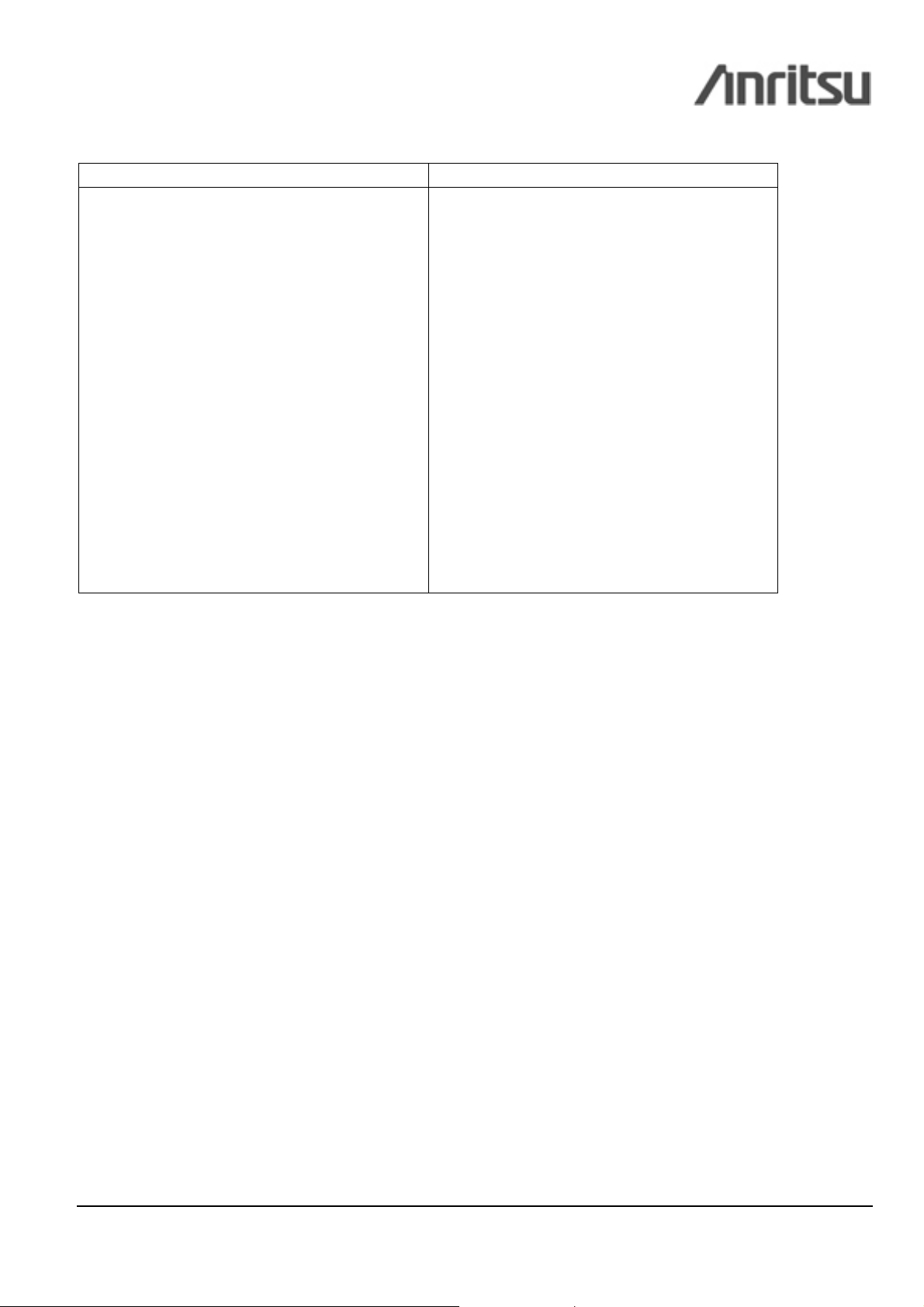
Testing APS switch time reaction of the network with 125 µs resolution
Due to the large amount of information being transferred over Synchronous Optical Network (SONET/SDH), it is extremely
important to ensure that the transport services are as readily available as possible.
APS -Automatic Protection Switching- is the protection mechanism that has been implemented in SDH/SONET networks in
order to guarantee the availability of the network in case of problems. The protection process involves switch actions between
working fibers and backup fibers. This process is completed when the equipments at both ends of the network have completed
these actions within the same 50 ms completion time. The result of this operation is the disappearance of the defaults because
the traffic is then transmitted on the backup channel.
The UTA-SDH/SONET application is able to detect defaults that may appear during a protection switch and displays their
duration with 125 µs resolution. With the ‘’Event Analysis” function of UTA, you have access to all the information from a
single window: total switch duration, details of all the events, partial duration for each event…
Fig.1: With the “Event Analysis” window, see all the defaults during the protection switch with 125 µs resolution.
ISO 9001:2000 certified. ICMA5KUTASTM64-SPEC05-0806-A4. ©2008 Anritsu. All Rights Reserved.
Page 3 of 14
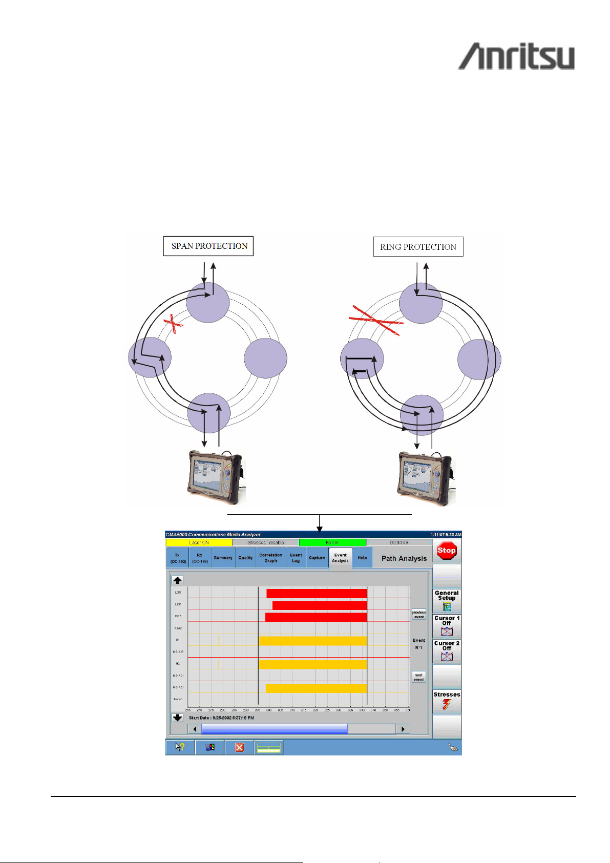
Auto-discovery of the signal structure
When performing tests in the field, it is sometimes difficult to configure the test equipment as the signal to be analyzed is not
always known: is the signal concatenated, what the frame mapping structure is, are the containers of the frame all equipped or
partially equipped? In such a situation, configuring the test equipment can be very painful and time consuming.
The “Structure Scan” function of the UTA application brings a smart solution to this type of problem.
“Structure Scan” automatically analyzes the signal and displays its frame structure in a graph for fast and easy interpretation.
The “Structure Scan” graph can give a complete overview of the frame down to the tributary and allows the automatic
configuration of the UTA application.
Fig.2: Discovering the frame structure of an unknown signal is easy with the “Structure Scan” function. Mix-payloads are also supported.
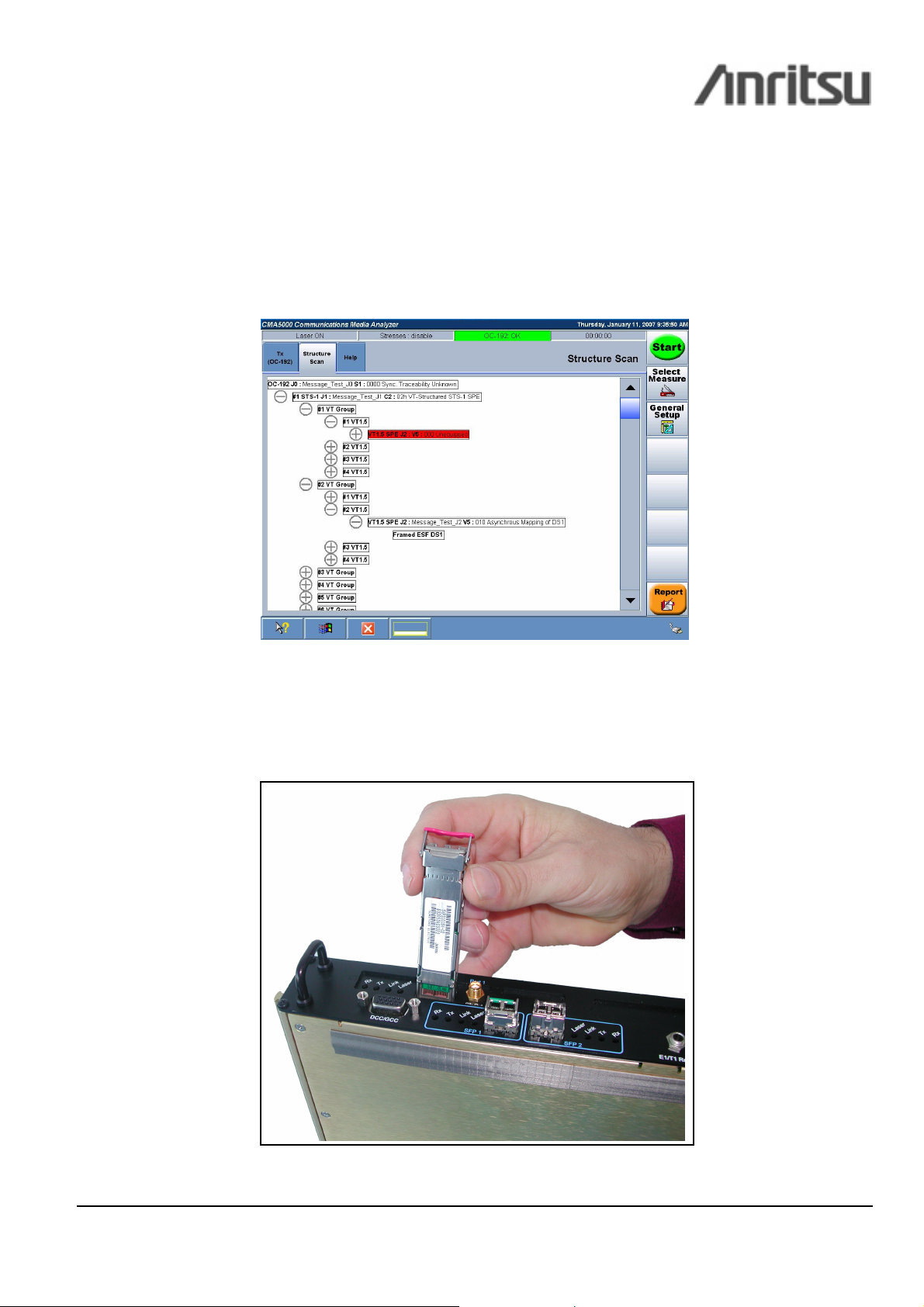
Field exchangeable XFP/SFP transceivers
The UTA module supports hot pluggable XFP/SFP transceivers. This feature brings a lot of configurability to the module. In
the field, the user just has to replace the XFP/SFP by another to change the optical interface characteristics. Whatever the
SDH/SONET link or equipment to test, the field engineer has the insurance to be able to equip his UTA module with the right
optical interface.
Fig.3: Change the optical interface of your module in the field via XFP/SFP transceiver
ISO 9001:2000 certified. ICMA5KUTASTM64-SPEC05-0806-A4. ©2008 Anritsu. All Rights Reserved.
Page 4 of 14
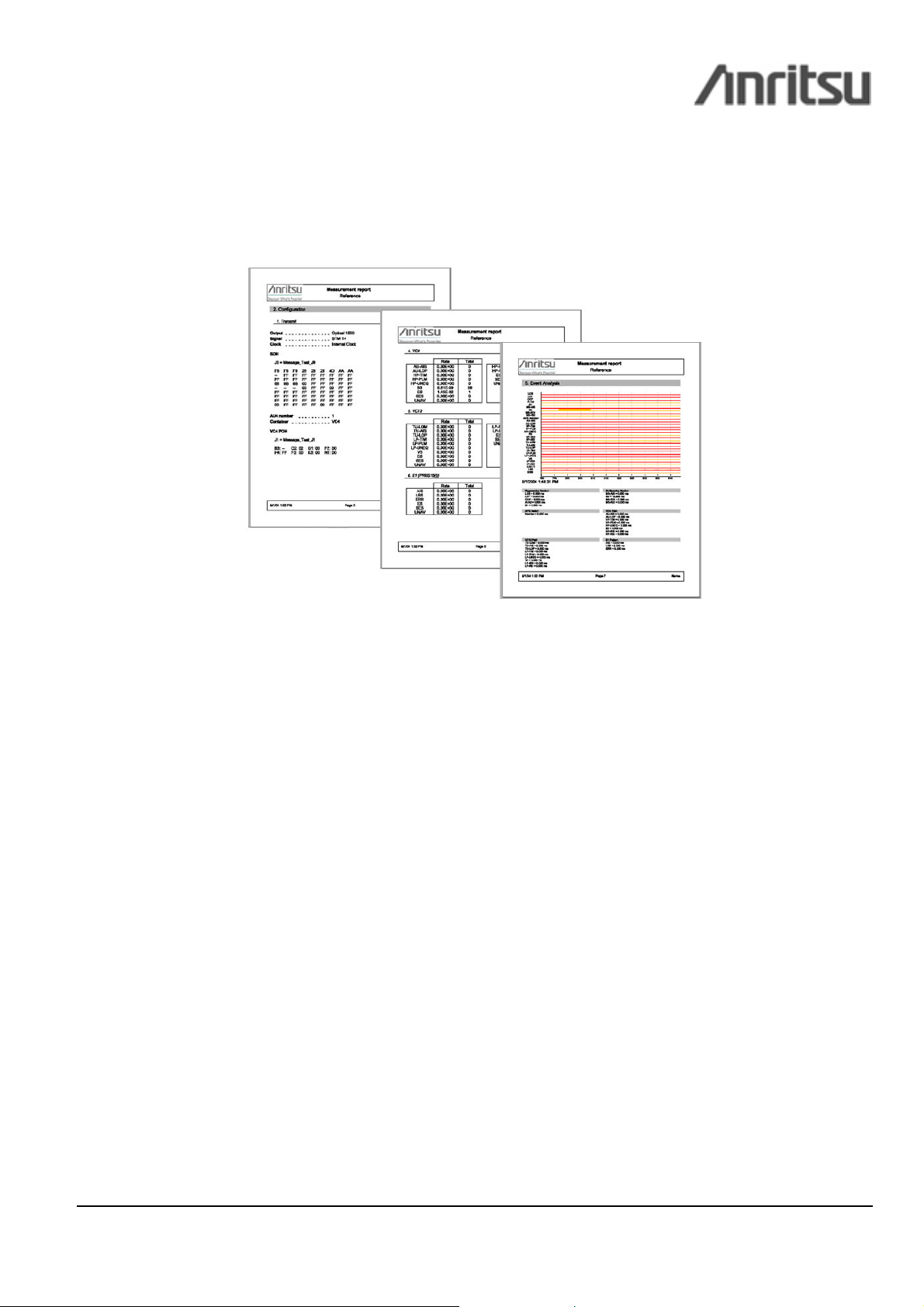
Fast and professional reports
Creating professional report has never been so easy with the UTA application. After stopping a measurement, the report is just
one click away: produce, save, print reports directly from the application. Select the set of results you want to produce, fill in
the header information associated with the measurement and the UTA application will generate professionally presented
reports in PDF format.
Fig.4: Generate automatic test report in PDF format with just one click
ISO 9001:2000 certified. ICMA5KUTASTM64-SPEC05-0806-A4. ©2008 Anritsu. All Rights Reserved.
Page 5 of 14

Specifications
Interfaces and Signal Specifications
Signal Port/Connector Format
STM-64 / OC-192 One XFP port
STM-1 / STM-4 / STM-16 (option)
OC-3 / OC-12 / OC-48 (option)
One SFP port
Bantam 100 Ohms E1 (2.048 Mb/s) / DS1 (1.544Mb/s)
1
1
- SDH: as per ITU-T G.707
- SONET: as per Telcordia GR-253-Core
- SDH: as per ITU-T G.707
- SONET: as per Telcordia GR-253-Core
Clock Input
Clock Output
Data Communication Channel DB-15 connector D1-D3: 192 Kb/s channel
BNC 75 Ohms 2.048MHz/1.544MHz/10MHz
BNC 75 Ohms 2.048MHz/1.544MHz
SMA 50 Ohms 622.08 MHz (with STM-4/16/64)
155.52 MHz (with STM-1)
D4-D12: 576 Kb/s channel
Optical Interfaces
Ref. Interfaces Wavelength Output Power Reach Overload Sensitivity
XFP
SFP
1,2
5610-141-UTA SR-1 / I-64-1 1290 – 1330 nm -6 to -1 dBm 10 km -1 dBm -11 dBm
5610-150-UTA SR-1 / I-64.1 1290 – 1330 nm -6 to -1dBm 10km -1dBm -11dBm
5610-142-UTA
5610-143-UTA
5610-144-UTA LR-1 / L-16.1 1280 – 1335 nm -2 to +3 dBm 40 km -9 dBm -27 dBm
5610-145-UTA
IR-2 / S-64.2b 1530 – 1565 nm -1 to +2 dBm 40km -1dBm -14dBm
LR-2/L-64.2 1530 – 1565 nm 0 to +4 dBm 80 km -7 dBm -24 dBm
LR-2 / L-16.2 1500 – 1580 nm -2 to +3 dBm 80 km -9 dBm -28 dBm
Clock Synchronization
Clock Reference
• Internal stratum 3 clock generation
• External 2.048 MHz reference clock
• Timed from 2.048 Mbit/s received signal
• External 1.544 MHz reference clock
• Timed from 1.544 Mbit/s received signal
• External 10 MHz reference clock
• Timed from SDH/SONET received signal
Notes
1
The XFP/SFP interfaces of the UTA module meet the requirements stated in the MSA standard
2
Requires XFP/SFP that must be ordered separately (see the ordering guide)
ISO 9001:2000 certified. ICMA5KUTASTM64-SPEC05-0806-A4. ©2008 Anritsu. All Rights Reserved.
Page 6 of 14

DCC Signals
The UTA-SDH/SONET application supports the drop and insert of DCC channels from SONET/SDH
• D1-D3: 192 Kb/s
• D4-D12: 576 Kb/s
SONET Mappings
ISO 9001:2000 certified. ICMA5KUTASTM64-SPEC05-0806-A4. ©2008 Anritsu. All Rights Reserved.
Page 7 of 14

SDH Mappings
Test Pattern
PRBS Patterns
Word Patterns
• PRBS: 29-1, 211-1, 215-1, 220-1, QRSS, 223-1, 229-1, 231-1 inverted and non-inverted
• All “1” pattern, all “0” pattern, alternative “01” pattern, “1000” pattern, “1010” pattern, user-
defined 2 bytes word pattern, 1 in 8, 2 in 8, 3 in 24, T1 Daly
ISO 9001:2000 certified. ICMA5KUTASTM64-SPEC05-0806-A4. ©2008 Anritsu. All Rights Reserved.
Page 8 of 14
SONET/SDH Overhead Editors
SONET
TOH Editor
POH Editor (STS)
POH Editor (VT)
SDH
SOH Editor
POH Editor (VC-4 and VC-3)
POH Editor (VC-12)
Error Addition
• All bytes of TOH (STS-1/STS-3) are programmable except B1/B2, H1/H2/H3 and Z0
• J0 (Trace Identifier):
o programmable 62 bytes ASCII sequence, CRLF added or
o programmable 15 bytes ASCII sequence, CRC (E.164) added or
o programmable byte
• C2, G1, F2, H4, Z3, Z4, N1
• J1 (Trace Identifier):
o programmable 62 bytes ASCII sequence, CRLF added or
o programmable 15 bytes ASCII sequence, CRC (E.164) added or
o programmable byte
• V5, Z6, Z7
• J2 (Trace Identifier):
o programmable 62 bytes ASCII sequence, CRLF added or
o programmable 15 bytes ASCII sequence, CRC (E.164) added or
o programmable byte
• All bytes of SOH (STM-1) are programmable except B1/B2 and H3
• J0 (Trace Identifier):
o programmable 15 bytes ASCII sequence, CRC (E.164) added or
o programmable 62 bytes ASCII sequence, CRLF added or
o programmable byte
• C2, G1, F2, H4, F3, K3, N1
• J1 (Trace Identifier):
o programmable 15 bytes ASCII sequence, CRC (E.164) added or
o programmable 62 bytes ASCII sequence, CRLF added or
o programmable byte
• V5, N2, K4
• J2 (Trace Identifier):
o programmable 15 bytes ASCII sequence, CRC (E.164) added or
o programmable 62 bytes ASCII sequence, CRLF added or
o programmable byte
SONET/DSn
SDH/PDH
Error Control
• A1/A2, B1, B2, REI-L, B3, REI-P, V5, REI-V, FAW (FAS), SFAW, FPS, MAW, Parity P,
Parity CP, F-bit, M-bit, FEBE, CRC-6, PRBS, Word, transmission errors
• A1/A2, B1, B2, MS-REI, B3, LP-B3, HP-REI, V5, LP-REI, FAW (FAS), CRC-4, REI (E-bit or
REBE), PRBS, Word, transmission errors
• Programmable number or rate
ISO 9001:2000 certified. ICMA5KUTASTM64-SPEC05-0806-A4. ©2008 Anritsu. All Rights Reserved.
Page 9 of 14

Alarm Addition
SONET/DSn
SDH/PDH
Alarm Control
Voice Add/Drop (Option)
SONET
SDH
Stress Function
Pointer Movement
Frequency Shift
• LOS, LOF, SEF, TIM-S, AIS-L, RDI-L, AIS-P, LOP-P, TIM-P, PLM-P, UNEQ-P, RDI-P,
LOM-V, AIS-V, LOP-V, PLM-V, UNEQ-V, RDI-V, TIM-V, RFI-V, LOMF, LSF, OOF, RAI,
IDLE, LSS, LPS, AIS
• LOS, LOF, OOF, RS-TIM, MS-AIS, MS-RDI, AU-AIS, AU-LOP, HP-PLM, HP-TIM,
HP-UNEQ, HP-RDI, TU-LOM, TU-AIS, TU-LOP, LP-PLM, LP-UNEQ, LP-TIM, LP-RDI,
LP-RFI, AIS, RDI, LOMF, LSS, LPS
• On steady-state or programmable number of frames
• Supports adding and dropping of a selected 64/56 kb/s voice channel (carried in a DSn
signal) to an external handset (µ-Law)
• NA
• Pointer movement generation on SONET and SDH frames:
o Pointer set to any value with or without NDF
o Positive and negative movements
o Pointer sequences (ITU-T G.783, Telcordia GR-253) :
SDH:
Single Alternating
Regular + Double
Regular + Missing
Double Alternating
Periodic 87.3
Periodic 87.3 with Add
Periodic 87.3 with Cancel
SONET:
Single
Burst of 3
Periodic
Periodic with Add
Periodic with Cancel
Periodic 87.3
Periodic 87.3 with Add
Periodic 87.3 with Cancel
Phase Transient
• Programmable frequency offset:
o -100 ppm to +100 ppm in 0.1 ppm steps SONET/SDH
APS (K1/K2)
SDH Through Mode
SONET Through Mode
DS1 Loop Codes
• Automatic Protection Switch messages (K1/K2) are user-programmable
• MSP Linear (ITU-T G.783) and MSP-Ring (ITU-T G.841) are supported
• SOH overwrite: J0, A1, A2, K1, K2, S1, M0, M1
• Error addition: A1A2, B1, B2, MS-REI, Transmission errors
• Alarm addition: LOS, LOF, OOF, MS-AIS, MS-RDI
• TOH overwrite: J0, A1, A2, K1, K2, S1, M0, M1
• Error addition: A1A2, B1, B2, REI-L, Transmission errors
• Alarm addition: LOS, LOF, SEF, AIS-L, RDI-L
• DS1 SF: Loop Up, Loop Down (CSU / NIU FAC1 / NIU FAC2)
• DS1 ESF: Line Loop Back Activate, Payload Loop Back Activate, Line Loop Back Deactivate,
Payload Loop Back Deactivate, Universal Loop Back Deactivate (In-Band, Out-of-Band)
ISO 9001:2000 certified. ICMA5KUTASTM64-SPEC05-0806-A4. ©2008 Anritsu. All Rights Reserved.
Page 10 of 14

Path Analysis
Signal Qualification
Errors Analysis
Alarms Analysis
Pointer Movement Analysis
Quality Analysis
Overhead Analysis
Event Analysis
• Power meter
• Frequency meter
• SONET/DSn
A1/A2, B1, B2, REI-L, B3, REI-P, V5, REI-V, FAW (FAS), SFAW, FPS, MAW, Parity P,
Parity CP, F-bit, M-bit, FEBE, CRC-6, PRBS, Word, ERR
• SDH/PDH
A1/A2, B1, B2, MS-REI, B3, LP-B3, HP-REI, V5, LP-REI, FAW (FAS), CRC-4, REI (E-bit or
REBE), PRBS, Word, ERR
• SONET/DSn
LOS, LOF, SEF, TIM-S, AIS-L, RDI-L, AIS-P, LOP-P, TIM-P, PLM-P, UNEQ-P, RDI-P,
LOM-V, AIS-V, LOP-V, PLM-V, UNEQ-V, RDI-V, TIM-V, RFI-V, OOF, LSF, LOMF, RAI,
IDLE, LSS, LPS, AIS
• SDH/PDH
LOS, LOF, OOF, RS-TIM, MS-AIS, MS-RDI, AU-AIS, AU-LOP, HP-PLM, HP-TIM,
HP-UNEQ, HP-RDI, TU-LOM, TU-AIS, TU-LOP, LP-PLM, LP-UNEQ, LP-TIM, LP-RDI,
LP-RFI, AIS, RDI, LOMF, LSS, LPS
• Pointer value
• Number of positive and negative pointer movements
• Number of pointer movement with NDF
• SONET
Transmission quality is calculated each second as per GR-253
• SDH/PDH
Transmission quality is calculated each second in accordance with recommendations G.826,
G.828, M.2100, M2101.1, M.2101, M.2110 for performance
• J0, J1 and J2 Path Trace messages (ASCII sequence)
• S1 (synchronization status)
• C2/V5 (signal label)
• Complete display of SOH/TOH and POH of the analyzed path channel
• Capture capacity: 64 consecutive frames
• Alarms and errors event analysis in temporal graphical display with 125 µs resolution
Round Trip Delay
• Measurement possible at each path level
• Resolution: 100 ns
• Range: 0 to 2 sec (depending on path level)
• Result: Maximum RTD, minimum RTD, Average RTD and errors/alarms detection
Automatic Protection Switching Measurement
• Number of switches
• Switch duration (with 125 µs resolution)
• K1/K2 capture and interpretation
ISO 9001:2000 certified. ICMA5KUTASTM64-SPEC05-0806-A4. ©2008 Anritsu. All Rights Reserved.
Page 11 of 14
Performance Analysis
• Direct graphical presentation of performance and availability conformance test result
• Automatic calculation of acceptance thresholds according to ITU-T recommandations, such as M.2100, M.2101.1 and M.2101
• Automatic calculation of Performance Objectives according to ITU-T recommendations such as G.826, G.828
Structure Scan
• Complete signal mapping auto discovery (including Mix Payload)
Trouble Scan
• Continuous VC-4/SPEs scanning for alarms and errors detection
ISO 9001:2000 certified. ICMA5KUTASTM64-SPEC05-0806-A4. ©2008 Anritsu. All Rights Reserved.
Page 12 of 14
Ordering Information
Ordering Information
5610-000-UTA
5610-201-UTA
Options
5610-211-UTA
5610-212-UTA
5610-213-UTA
5610-214-UTA
5610-215-UTA
5610-216-UTA
5610-239-UTA
Accessories
5610-141-UTA
5610-150-UTA
5610-142-UTA
5610-143-UTA
5610-144-UTA
5610-145-UTA
Upgrades
5610-261-UTA
5610-262-UTA
5610-263-UTA
5610-264-UTA
5610-265-UTA
5610-266-UTA
Note 1: For best performance, the CMA5000 platform must have 512M RAM when using UTA with more than one
application.
Note 2: All the 10G/11G applications are field upgradeable.
For upgrades with reference 5610-266-UTA, customers must call their Anritsu contact with module Serial
Number as hardware upgrade might be required.
ISO 9001:2000 certified. ICMA5KUTASTM64-SPEC05-0806-A4. ©2008 Anritsu. All Rights Reserved.
UTA base module
*Applications must be ordered separately
10 Gig SONET/SDH application (XFP not included)
Concatenation option for 10 Gig SONET/SDH application
Voice add/drop option for 10 Gig SONET/SDH application (only available for SONET)
Tandem Connection Monitoring option for 10 Gig SONET/SDH application
ATM option 10 Gig SONET/SDH application
Virtual Concatenation Monitoring option (VCAT, LCAS, Diff.Delay) for High Order for 10 Gig SONET/SDH
application
‘’STM-1/4/16 and OC-3/12/48” option for 10 Gig SDH/SONET application (SFP not included)
Remote Command for SDH/SONET application (via Ethernet)
Remark: Voice Add/Drop / ATM / VCAT Monitoring options are not supported by remote commands
1310 nm XFP (10 km) transceiver (LC connector)
*Multi-rates XFP supporting STM-64/OC-192/10 GigE
1310 nm XFP (10 km) transceiver (LC connector)
*Multi-rates XFP supporting STM-64/OC-192/10 GigE/OTU-2
1550 nm XFP transceiver (40 km) (LC connector)
*Multi-rates XFP supporting STM-64/OC-192/10 GigE/OTU-2
1550 nm XFP transceiver (80 km) (LC connector)
*Multi-rates XFP supporting STM-64/OC-192/10 GigE/OTU-2
1310 nm SFP transceiver (40 km) (LC connector)
* Multi-rates SFP supporting STM-1/4/16 & OC-3/12/48 & OTU-1
1550 nm SFP transceiver (80 km) (LC connector)
* Multi-rates SFP supporting STM-1/4/16 & OC-3/12/48 & OTU-1
UTA module upgrade with “Concatenation” option
UTA module upgrade with “Voice add/Drop” option
UTA module upgrade with “Tandem Connection Monitoring” option
UTA module upgrade with “ATM” option
UTA module upgrade with “VCAT Monitoring” option
UTA module upgrade with “STM-1/4/16 and OC-3/12/48 option (SFP not included)
Page 13 of 14

1 Science Museum Road,
Anritsu Corporation
5-1-1 Onna, Atsugi-shi, Kanagawa, 243-8555
Japan
Phone: +81-46-223-1111
Fax: +81-46-296-1264
•
U.S.A.
Anritsu Company
1155 East Collins Blvd., Richardson, TX 75081,
U.S.A.
Toll Free: 1-800-ANRITSU (267-4878)
Phone: +1-972-644-1777
Fax: +1-972-671-1877
•
Canada
Anritsu Electronics Ltd.
700 Silver Seven Road, Suite 120, Kanata,
Ontario K2V 1C3, Canada
Phone: +1-613-591-2003
Fax: +1-613-591-1006
•
Brazil
Anritsu Eletrônica Ltda.
Praca Amadeu Amaral, 27 - 1 Andar
01327-010-Paraiso-São Paulo-Brazil
Phone: +55-11-3283-2511
Fax: +55-11-3288-6940
•
Mexico
Anritsu Company, S.A. de C.V.
Av. Ejército Nacional No. 579 Piso 9, Col.
Granada, 11520 México, D.F., México
Phone: +52-55-1101-2370
Fax: +52-55-5254-3147
•
U.K.
Anritsu EMEA Ltd.
200 Capability Green, Luton, Bedfordshire LU1
3LU, U.K.
Phone: +44-1582-433200
Fax: +44-1582-731303
•
France
Anritsu S.A.
16/18, Avenue du Québec, SILIC 720
91961 COURTABOEUF Cedex, France
Phone: +33-1-60-92-15-50
Fax: +33-1-64-46-10-65
•
Germany
Anritsu GmbH
Nemetschek Haus, Konrad-Zuse-Platz 1
81829 München, Germany
Phone: +49-89-442308-0
Fax: +49-89-442308-55
•
Italy
Anritsu S.p.A.
Via Elio Vittorini, 129, 00144 Roma, Italy
Phone: +39-6-509-9711
Fax: +39-6-502-2425
•
Sweden
Anritsu AB
Borgafjordsgatan 13, 164 40 KISTA, Sweden
Phone: +46-8-534-707-00
Fax: +46-8-534-707-30
•
Finland
Anritsu AB
Teknobulevardi 3-5, FI-01530 Vantaa, Finland
Phone: +358-20-741-8100
Fax: +358-20-741-8111
•
Denmark
Anritsu A/S
Kirkebjerg Allé 90, DK-2605 Brøndby, Denmark
Phone: +45-72112200
Fax: +45-72112210
•
Spain
Anritsu EMEA Ltd.
Oficina de Representación en España
Edificio Veganova
Avda de la Vega, n° 1 (edf 8, pl 1, of 8)
28108 ALCOBENDAS - Madrid, Spain
Phone: +34-914905761
Fax: +34-914905762
•
Russia
Anritsu EMEA Ltd.
Representation Office in Russia
Tverskaya str. 16/2, bld. 1, 7th floor.
Russia, 125009, Moscow
Phone: +7-495-363-1694
Fax: +7-495-935-8962
•
United Arab Emirates
Anritsu EMEA Ltd.
Dubai Liaison Office
P O Box 500413 - Dubai Internet City
Al Thuraya Building, Tower 1, Suit 701, 7th
Floor
Dubai, United Arab Emirates
Phone: +971-4-3670352
Fax: +971-4-3688460
Please Contact :
•
Singapore
Anritsu Pte Ltd.
60 Alexandra Terrace, #02-08, The Comtech
(Lobby A), Singapore 118502
Phone: +65-6282-2400
Fax: +65-6282-2533
•
India
Anritsu Pte. Ltd.
India Branch Office
Unit No. S-3, Second Floor, Esteem Red Cross
Bhavan, No 26, Race Course Road,
Bangalore 560 001, India
Phone: +91-80-32944707
Fax: +91-80-22356648
•
P.R. China (Hong Kong)
Anritsu Company Ltd.
Units 4 & 5, 28th Floor, Greenfield Tower,
Concordia Plaza, No.
Tsim Sha Tsui East, Kowloon, Hong Kong
Phone: +852-2301-4980
Fax: +852-2301-3545
•
P.R. China (Beijing)
Anritsu Company Ltd.
Beijing Representative Office
Room 1515, Beijing Fortune Building,
No. 5, Dong-San-Huan Bei Road,
Chao-Yang District, Beijing 10004, P.R. China
Phone: +86-10-6590-9230
Fax: +86-10-6590-9235
•
Korea
Anritsu Corporation, Ltd.
8F Hyunjuk Building, 832-41, Yeoksam dong,
Kangnam-ku, Seoul, 135-080, Korea
Phone: +82-2-553-6603
Fax: +82-2-553-6604
•
Australia
Anritsu Pty Ltd.
Unit 21 / 270 Ferntree Gully Road,
Notting Hill, Victoria 3168 Australia
Phone: +61-3-9558-8177
Fax: +61-3-9558-8255
•
Taiwan
Anritsu Company Inc.
7F, No. 316, Sec. 1, Neihu Rd., Taipei 114,
Taiwan
Phone: +886-2-8751-1816
Fax: +886-2-8751-1817
ISO 9001:2000 certified. ICMA5KUTASTM64-SPEC05-0806-A4. ©2008 Anritsu. All Rights Reserved.
Page 14 of 14
 Loading...