

209
FREQUENCY SYNTHESIZERS, SIGNAL GENERA TORS
GPIB
SYNTHESIZED SIGNAL GENERA T OR
MG3633A
10 kHz to 2700 MHz
5
The MG3633A has excellent frequency resolution, frequency switching
speed, signal purity, and a high output level in addition to amplitude, fre quency, and phase modulation functions.
Also, sweep functions are provided for carrier frequency, output level,
and modulation frequency so an appropriate sweep can be performed
for various devices to be measured. Also, the MG3633A has a frequency memory that can store 1000 carrier frequencies and a function
memory that stores 100 panel settings. Moreover, since the maximum
output level is +17 dBm, it can be used for various local signal sources.
The MG3633A is suitable for research and development of mobile
communications in the quasi-microwave band, performance evaluation, characteristics testing, and adjustment of various types of radio
equipment such as digital land-based mobile communications, mobile
satellite communications, satellite broadcasting, and radio LANs.
Features
• Low noise
By using both the latest synthesizer and RF-device technologies and
optical data links in the internal control circuit, the SSB phase noise
has been cut to –140 dBc/Hz (CW, 1.1 GHz, offset 20 kHz). In particular, the MG3633A shows its power in measurement of narrowband radio equipment S/N ratio and adjacent channel selectivity.
• High accuracy and high-output level
Low levels of –123 dBm can be set with ±1 dB accuracy by using a
high-accuracy programmable attenuator.
The output level can be displayed in units of dBm, dBµV, V, mV, and
µV or as a relative value (dB).
• Modulation characteristics
The MG3633A has AM, FM, øM and a combination of all three modulation functions. A DC mode is provided for FM which makes simulation of digital transmissions for a pager possible. Also, a built-in AF
oscillator with a 0.1 Hz to 100 kHz synthesizer can handle various
modulations.
• Quasi-microwave output
The MG3633A covers a wide range – from 10 kHz to 2700 MHz – and
is suitable for research and development, as well as production of
quasi-microwave band radio equipment.
Performance
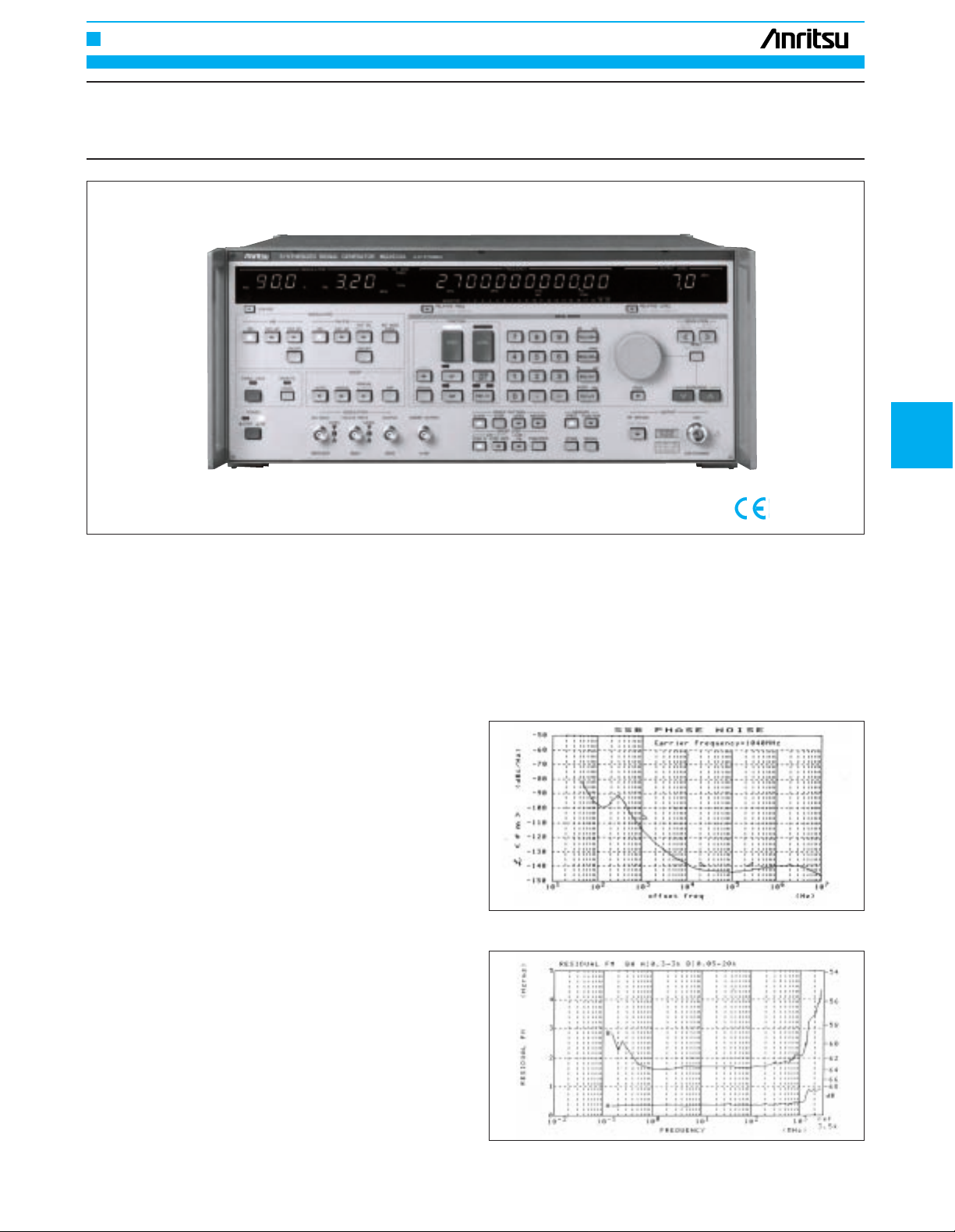
• Signal purity
The MG3633A has excellent spectral purity. As shown in the Fig. 1,
the SSB phase noise at 1 GHz with 20 kHz signal offset is –140
dBc/Hz. In particular, this shows its power for generating signals
used for testing radio receiver selectivity, for generating high-speed
clocks of A/D converters and dividers, as well as for generating standard signals for communications links.
Also, since the residual FM is 0.8 Hz rms or less (1.28 GHz or less),
even the S/N ratio of narrow-band mobile radio equipment can be
measured with sufficient margin (Fig. 2)
Fig. 1 SSB phase noise
Fig. 2 Residual FM

FREQUENCY SYNTHESIZERS, SIGNAL GENERAT ORS
210
• Output level characteristics
A maximum output of +17 dBm can be obtained over a wide frequency range so 2-signal or 3-signal testing can be done easily.
A high-accuracy highly-reliable programmable attenuator (life cycle
over 3 million times) is used and since flat output characteristics are
obtained by internal calibration over a wide range from 10 kHz to 2.7
GHz, it is effective for testing antennas and cables (Fig. 3).
Moreover, compensation data for obtaining flat levels at cable ends
can be input by using a power meter, GPIB, controller, and frequency-response compensation software (option).
• Continuously variable output level
The MG3633A can output continuously-variable signals in a 20 dB
range with 0.1 dB steps at any level.
This is especially convenient for measuring the dynamic range of
magnetic tape and squelch sensitivity of radios which produce hysteresis phenomenon as a result of level variation.
• AM
A high-accuracy AM wave is generated over a wide frequency range
(Fig. 4). Countermeasures against carrier-wave variation due to vibration permit even SSB radio equipment to be tested with confidence.
• FM
FM with a maximum frequency deviation of 3.2 MHz is possible (1.28
to 2.7 GHz). Also if the frequency deviation is too low, automatic operation is carried out in the stabilized DC-FM mode so even digital
data transmission equipment such as pagers can be tested (Fig. 5).
Fig. 3 Output level frequency response
Fig. 4 AM modulation frequency characteristics
Fig. 5 FM modulation frequency characteristics
Specifications
Continued on next page
Carrier
frequency
Range
Resolution
Accuracy
Internal reference
oscillator
*
1
External reference
signal input
Reference signal output
Switching time
Range
Units
Resolution
Frequency response
Accuracy
Impedance
Switching time
Interference radiation
10 kHz to 2700 MHz
0.01 Hz
Same as that of the reference oscillator
Frequency: 10 MHz
Start-up characteristics: After 30 minutes of operation: ≤1 x 10
–7
/day, after 60 minutes of operation: ≤5 x 10⁻⁸/day,
Aging rate: After 24 hours of operation: ≤2 x 10
–8
/day,
Temperature characteristics: ±5 x 10
–8
/day, (0˚ to 50˚C)
10 MHz, TTL Level, BNC connector on rear panel
10 MHz, TTL Level, BNC connector on rear panel
≤10 ms (time from last command until frequency has stabilized to within ±500 Hz of set frequency, during remote
operation)
–143 to +23 dBm
dBm, dBµV, V, mV, µV (Terminated and open voltages are selectable for dBµV, V, mV or µV.)
0.1 dB
±0.5 dB referred to 0 dBm (<1280 MHz), ±1 dB referred to 0 dBm (≥1280 MHz)
50 Ω, N-type connector
VSWR: ≤1.5 (<1280 MHz, ≤–3 dBm), ≤1.8 (≥1280 MHz, ≤–3 dBm)
Time from last command until output level is stabilized, during remote operation:≤25 ms (at LEVEL NORMAL mode)
≤80 ms (when setting level is crossing over –59 dBm, at LEVEL NORMAL mode)
≤5 ms (at LEVEL CONTINUOUS mode)
≤1 µV (Value is voltage terminated with 50 Ω load, measured 25 mm from front panel with a two-turn 25 mm
diameter loop antenna.) Except sweep mode
Output
Frequency
Output level
+17.1 to +23 dBm –
±1 dB
±1 dB
±3 dB
–
–
–
±2 dB
±4 dB
–
+15.1 to +17 dBm
–122.9 to +15 dBm
–132.9 to –123 dBm
–143 to –133 dBm
10 kHz to <1280 MHz ≥1280 MHz
 Loading...