

Page 1

MODEL
ME7840A
POWER AMPLIFIER TEST SYSTEM
OPERATION AND
MAINTENANCE MANUAL
490 JARVIS DRIVE - MORGAN HILL, CA 95037-2809
P/N: 10410-00225
REVISION: A
PRINTED: JUNE 2000
COPYRIGHT 2000 ANRITSU CO
Page 2

WARRANTY
The ANRITSU product(s) listed on the title page is (are) warranted against defects in materials and
workmanship for three years from the date of shipment.
ANRITSU’s obligation covers repairing or replacing products which prove to be defective during the
warranty period. Buyers shall prepay transportation charges for equipment returned to ANRITSU for
warranty repairs. Obligation is limited to the original purchaser. ANRITSU is not liable for consequential
damages.
LIMITATION OF WARRANTY
The foregoing warranty does not apply to ANRITSU connectors that have failed due to normal wear. Also,
the warranty does not apply to defects resulting from improper or inadequate maintenance by the Buyer,
unauthorized modification or misuse, or operation outside of the environmental specifications of the
product. No other warranty is expressed or implied, and the remedies provided herein are the Buyer’s sole
and exclusive remedies.
TRADEMARK ACKNOWLEDGEMENTS
V Connector and K Connector are registered trademarks of ANRITSU Company.
GPC-7 is a registered trademark of Amphenol Corporation.
Ink Jet and Think Jet are registered trademarks of Hewlett-Packard Co.
MS-DOS is a registered trademark of Microsoft Corporation.
NOTICE
ANRITSU Company has prepared this manual for use by ANRITSU Company personnel and customers
as a guide for the proper installation, operation and maintenance of ANRITSU Company equipment and
computer programs. The drawings, specifications, and information contained herein are the property of
ANRITSU Company, and any unauthorized use or disclosure of these drawings, specifications, and
information is prohibited; they shall not be reproduced, copied, or used in whole or in part as the basis for
manufacture or sale of the equipment or software programs without the prior written consent of ANRITSU
Company.
Page 3

Page 4

Page 5

Safety Symbols
To prevent the risk of personal injury or loss related to equipment malfunction, ANRITSU Company uses
the following symbols to indicate safety-related information. For your own safety, please read the informa
tion carefully BEFORE operating the equipment.
Symbols used in manuals
-
DANGER
This indicates a very dangerous procedure that could result in serious
injury or death if not performed properly.
WARNING This indicates a hazardous procedure that could result in serious in
jury or death if not performed properly.
CAUTION This indicates a hazardous procedure or danger that could result in
light-to-severe injury, or loss related to equipment malfunction, if
proper precautions are not taken.
Safety Symbols Used on Equipment and in Manuals
(Some or all of the following five symbols may or may not be used on all ANRITSU equipment. In addition,
there may be other labels attached to products that are not shown in the diagrams in this manual.)
The following safety symbols are used inside or on the equipment near operation locations to provide infor
mation about safety items and operation precautions. Ensure that you clearly understand the meanings of
the symbols and take the necessary precautions BEFORE operating the equipment.
This indicates a prohibited operation. The prohibited operation is indi
cated symbolically in or near the barred circle.
-
-
-
This indicates a compulsory safety precaution. The required operation
is indicated symbolically in or near the circle.
This indicates warning or caution. The contents are indicated symboli
cally in or near the triangle.
This indicates a note. The contents are described in the box.
These indicate that the marked part should be recycled.
ME7840A OMM Safety 1
-
Page 6

For Safety
WARNING
Always refer to the operation manual when working near locations at
which the alert mark, shown on the left, is attached. If the operation,
etc., is performed without heeding the advice in the operation manual,
there is a risk of personal injury. In addition, the equipment perfor
mance may be reduced.
Moreover, this alert mark is sometimes used with other marks and de
scriptions indicating other dangers.
WARNING
When supplying power to this equipment, connect the accessory 3-pin
power cord to a 3-pin grounded power outlet. If a grounded 3-pin outlet
is not available, use a conversion adapter and ground the green wire, or
connect the frame ground on the rear panel of the equipment to ground.
If power is supplied without grounding the equipment, there is a risk of
receiving a severe or fatal electric shock.
-
-
Repair
WARNING
This equipment can not be repaired by the operator. DO NOT attempt to
remove the equipment covers or to disassemble internal components.
Only qualified service technicians with a knowledge of electrical fire
and shock hazards should service this equipment. There are
high-voltage parts in this equipment presenting a risk of severe injury
or fatal electric shock to untrained personnel. In addition, there is a
risk of damage to precision components.
WARNING
Use two or more people to lift and move this equipment, or use an
equipment cart. There is a risk of back injury, if this equipment is lifted
by one person.
Safety 1 ME7840A OMM
Page 7

Table of Contents
Chapter 1 General Information
SCOPE OF THIS MANUAL...............................1-1
INTRODUCTION ....................................1-1
RELATED MANUALS .................................1-1
CONVENTIONS.....................................1-2
SERIAL NUMBER ...................................1-2
ONLINE MANUALS ..................................1-2
PATS SYSTEM OVERVIEW ..............................1-2
HARDWARE DESCRIPTION..............................1-2
SYSTEM DESCRIPTION ................................1-5
DRA Scorpion ....................................1-5
MS4782X Test Set .................................1-6
Connectors and Ports ................................1-7
K FACTOR........................................1-9
ADAPTIVE P STOP ...................................1-9
SOFTWARE DESCRIPTION ..............................1-9
TEST EXECUTIVE ...................................1-9
SOFTWARE STRUCTURE ..............................1-11
MS7840A OPTIONS ..................................1-12
OPTIONAL ACCESSORIES..............................1-12
PREVENTIVE MAINTENANCE ...........................1-13
USER SUPPLED TEST SET .............................1-13
PERFORMANCE SPECIFICATIONS.........................1-13
RECOMMENDED ITEMS...............................1-15
USER SUPPLIED ITEMS ...............................1-15
Chapter 2 Installation
INTRODUCTION ....................................2-1
EQUIPMENT COMPLEMENT .............................2-1
UNPACKING and INSPECTION............................2-1
INSTALLATION - HARDWARE ............................2-2
INSTALLATION - SOFTWARE.............................2-7
ME7840A OMM i
Page 8

Installation .....................................2-7
What else is on the CD?...............................2-7
Uninstalling the software..............................2-7
SERVICE CENTERS ..................................2-8
Chapter 3 Operations, General
INTRODUCTION ....................................3-1
PREPARING THE SYSTEM ..............................3-1
Unused Connections ................................3-2
USING PATS SOFTWARE ...............................3-4
Software
Organization.....................................3-4
COLLATERALFUNCTIONS ..............................3-5
File..........................................3-5
Help .........................................3-6
Tools .........................................3-7
Chapter 4 Operations, Calibration
INTRODUCTION ....................................4-1
OPERATION, GENERAL ................................4-1
PROGRAM FILES....................................4-1
TEST EQUIPMENT...................................4-2
GENERAL ........................................4-3
POWER LEVEL .....................................4-4
HOTS22.........................................4-8
S-PARAMETERS CAL .................................4-11
CAL FILE SETUP ...................................4-15
Chapter 5 Operations, Measurement
INTRODUCTION ....................................5-1
OPERATION, GENERAL ................................5-1
MEASUREMENT CALIBRATION ...........................5-1
GENERAL ........................................5-1
Calibration(s) Completed ..............................5-1
Calibration(s) Not Completed ...........................5-2
S-PARAMETER TESTS: S
S-PARAMETER TEST: K FACTOR...........................5-7
POWER SWEEP, TWO TONE.............................5-10
Single Frequency Power Sweep ..........................5-10
Multiple Frequency Power Sweep.........................5-14
21,S11,S22,S12
,ALL.....................5-4
ii ME 7840A OMM
Page 9

Gain and IMD Power Sweep ...........................5-18
POWER SWEEP, ONE TONE .............................5-22
Single Frequency Power Sweep ..........................5-22
IMD...........................................5-26
HARMONICS .....................................5-29
HOTS22........................................5-32
Chapter 6 Performance Verification Procedure
INTRODUCTION ....................................6-1
CONVENTIONS.....................................6-1
TEST
EQUIPMENT ......................................6-1
SOURCE OUTPUT ACCURACY ............................6-2
Setup: ........................................6-2
Test Procedure ...................................6-2
RETURN LOSS CONFIDENCE TEST.........................6-3
Setup.........................................6-3
Test Procedure: ...................................6-4
SYSTEM DYNAMIC RANGE .............................6-6
Test Procedure: ...................................6-6
RECEIVER DISPLAY LINEARITY ..........................6-8
Setup: ........................................6-8
Chapter 7 Preamplifier Operations
INTRODUCTION ....................................7-1
USE OF EXTERNAL PREAMPLIFIERS........................7-1
Alternative 1 ....................................7-1
Alternative 2 ....................................7-1
Appendix A Calibration Specification Files
INTRODUCTION ....................................A-1
FILE TYPES.......................................A-1
OPEN FILES ......................................A-1
TECHNICAL DETAILS.................................A-1
POWER LEVE.TXT ..................................A-11
CAL FILES SETUP.TXT................................A-11
HOT S
.TXT ......................................A-13
22
S-PARAMETERS. TXT ................................A-14
ME7840A OMM iii/iv
Page 10

Page 11

Figure 1-1. Model ME7840A Power Amplifier Test System (PATS)
Page 12

Chapter 1 General Information
1-1 SCOPE OF THIS
MANUAL
This manual provides operating and maintenance information for the
ME7840A Power Amplifier Test System (PATS, Figure 1-1). The follow
ing topics are discussed:
Equipment Description
q
Equipment Installation and Connection
q
Software Description
q
Software Installation
q
Calibration
q
System Operation
q
Test Procedures and Test Results Interpretation
q
System Performance Verification
q
The procedures described in this manual presume a working knowledge
of vector network analyzers and RF power amplifier testing procedures.
Refer to the other manuals supplied with the ME7840A (see below) for
more detailed explanations of the system equipment and procedures.
1-2 INTRODUCTION This chapter provides information to familiarize the user with the basic
ME7840A Power Amplifier Test System. Included is information about re
lated manuals, and the available models and options.
1-3 RELATED
MANUALS
The ME7840A manual set consists of the following manuals: The operat
ing and programming manuals are supplied with the equipment; the
maintenance manuals are optional items that may be purchased.
-
-
-
Manual Description ANRITSU Part Number
ME7840A Operating & Maintenance Manual
(OMM)
MS462XX Operating Manual (OM) 10410-00203
MS462XX Programming Manual (PM) 10410-00204
MS462XX Maintenance Manual (MM) 10410-00205 (Optional)
MS4782X Test Set Maintenance Manual (MM) 10410-00218 (Optional))
10410-00225
ME7840A OMM 1-1
Page 13

CONVENTIONS GENERAL INFORMATION
1-4 CONVENTIONS Throughout this manual, the ME7840A Power Amplifier System may be
referenced as PATS or ME7840A; the MS462XC may be referenced as
Scorpion or MS462XC; and the MS4782X Test Set may be referenced as
Test Set or MS4782X.
1-5 SERIAL NUMBER All ANRITSU instruments are assigned a unique six-digit serial number,
such as “940101.” This number is affixed to a decal on the rear panel of
each unit. In any correspondence with ANRITSU Customer Service,
please use this number.
1-6 ONLINE MANUALS This manual is available on CD ROM as an Adobe Acrobat™ (*.pdf) file.
The file can be viewed using Acrobat Reader™, a free program that is
also available on the CD ROM. This file is “linked” such that the viewer
can choose a topic to view from the displayed “bookmark” list and “jump”
to the manual page on which the topic resides. The text can also be
word-searched. CD ROM part numbers are available on ANRITSU’s
Internet home page (http://www.global.anritsu.com/ library/). You can also
contact ANRITSU Customer Service for price and availability.
1-7 PATS SYSTEM
OVERVIEW
1-8 HARDWARE
DESCRIPTION
The ANRITSU ME7870A Power Amplifier Test System (PATS) is intended for the measurement and real-time graphical display of the following parameters of a power amplifier in the frequency range of 10 MHz to
6 GHz:
q
S-Parameters including Hot S
q
K Factor
q
Gain Compression and Phase Distortion
q
Intermodulation Distortion
q
Harmonics
q
Drain Current and Power Added Efficiency (PAE)
PATS is designed to facilitate alignment, tuning and pass/fail testing of
the components, modules and subassemblies of a power amplifier as well
as the completed amplifier.
The ME7840A hardware (Figure 1-1) consists of a MS462XC, Direct Re
ceiver Access (DRA) Scorpion, a MS4782X Test Set, a customer supplied
Personal Computer (PC), and an optional current probe (refer to Chapter
2, Figure 2-4 ). The MS462XC is available in two frequency ranges: 10
MHz to 3 GHz or 10 MHz to 6 GHz.
The Test Set is available in two configurations, as described in Table 1-1
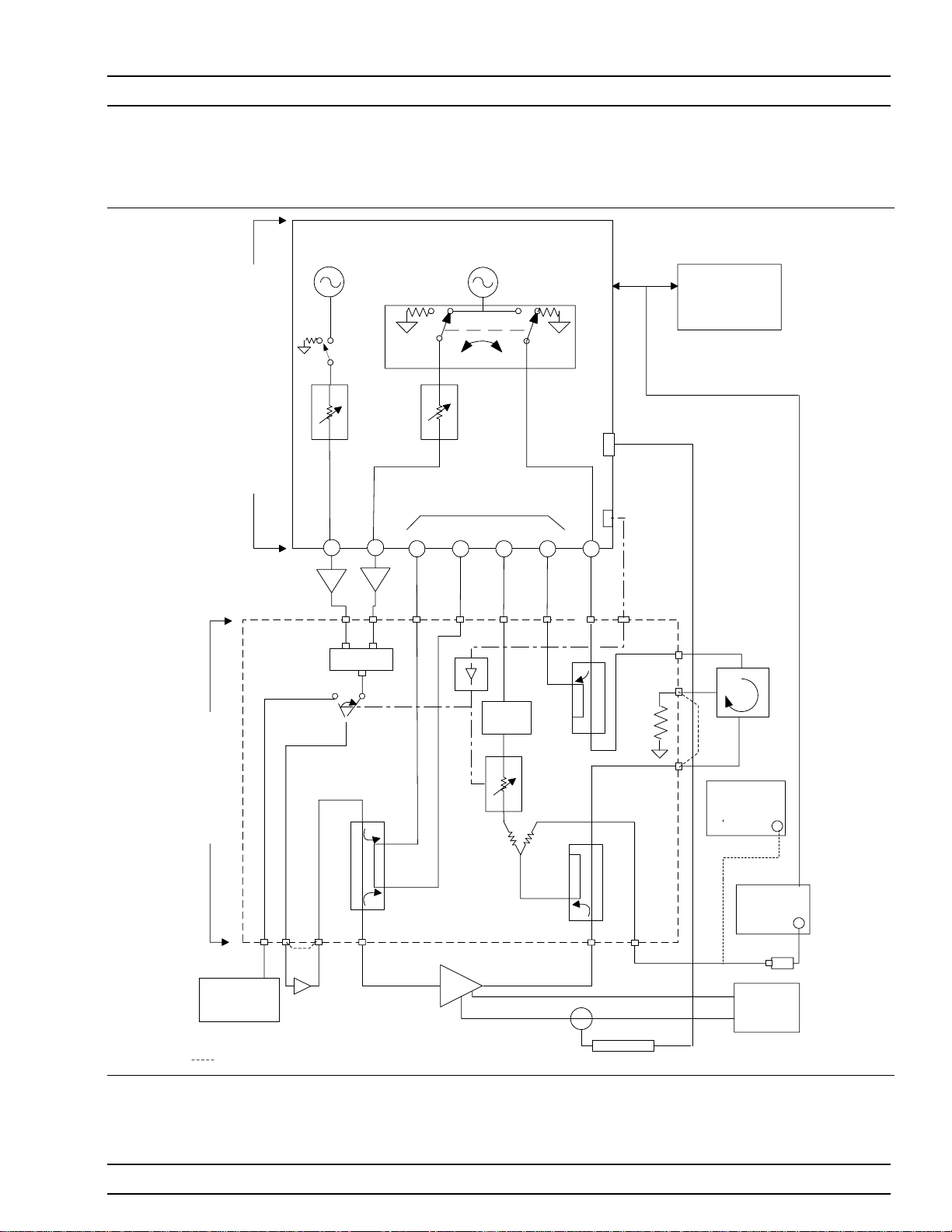
The MS4782D is standard, and the MS4782A is Option 2. A block dia
gram of the PATS is shown in Figure 1-2 and the Option 2 system in Fig
ure 1-3.
22
-
-
-
1-2 ME 7840A OMM
Page 14
GENERAL INFORMATION HARDWARE DESCRIPTION
SOURCE 2 SOURCE 1
MS4782D Test Set
ACCESS
SCORPION
DIRECT RECEIVER
OPTIONAL
EXTERNAL
PREAMPLIFIERS
ATTENUATORS
70dB, 10dB/step
RF3
N
N
COMBINER
-30dB
STEP
RF1
REVERSE
FORWAR
D
TRANSFER SWITCH
GPIB
ANALOG IN
SYSTEM
CONTROLLER
(PC)
GPIB
RECEIVERS
EXT I/O
a
b
1
1
N
KKKN
K
LIMITER
STEP
ATTENUATOR
70dB, 10dB/step
a
b
2
2
K
KKN
RF2
-30dB
CONTROL
LINES
NK
K
C3
K
C2
EXTERNAL
100 W
TERMINATION
K
C1
CIRCULATOR
OPTIONAL
SPECTRUM
ANALYZER
NK
OPTIONAL
MODULATION
SYNTHESIZER
OPTIONAL
EXTERNAL
PRE-AMP
-30dB
N
K
-30dB
N
N
AUT
POWER
METER
POWER
SUPPLY
CURRENT PROBE
Indicates coaxjumper in the as-shipped configuration
Figure 1-2. Overall Functional Block Diagram of the Basic Power Amplifier Test System (PATS) with MS4782D Test Set
ME7840A OMM 1-3
Page 15

HARDWARE DESCRIPTION GENERAL INFORMATION
SOURCE 2 SOURCE 1
ACCESS
SCORPION
DIRECT RECEIVER
OPTIONAL
EXTERNAL
PREAMPLIFIERS
ATTENUATORS
70dB, 10dB/step
RF3
N
N
COMBINER
STEP
RF1
REVERSE
FORWAR
D
TRANSFER SWITCH
GPIB
ANALOG IN
SYSTEM
CONTROLLER
(PC)
GPIB
RECEIVERS
EXT I/O
a
b
1
1
N
KKKN
K
a
b
2
K
KKN
RF2
2
CONTROL
LINES
NK
-30dB
LIMITER
ER
POW
OPTIONAL
SPECTRUM
ANALYZER
POWER
METER
POWER
SUPPLY
MS478A Test Set
NK
OPTIONAL
MODULATION
SYNTHESIZER
OPTIONAL
EXTERNAL
PRE-AMP
HIGH
STEP
ATTENUATOR
-30dB
-30dB
N
K
70dB, 10dB/step
-30dB
N
TERMINATION
N
AUT
CURRENT PROBE
Indicates coaxjumper in the as-shipped configuration
Figure 1-3. Overall Functional Block Diagram of the Option 2 Power Amplifier Test System (PATS) with MS4782A Test
Set
1-4 ME 7840A OMM
Page 16

GENERAL INFORMATION SYSTEM DESCRIPTION
Table 1-1. Test Set Configurations
Model
MS4782A 800 to 1000 50 Yes Internal
MS4782D 800 to 2400
Notes:
1. This frequency range does not account for any restricting effects caused by use of external circulator.
2. This Max AUT power assumes a minimum isolation of 23 dB provided by external circulator(s). Two circulators may have to
be used to provide the required isolation.
Frequency Range
(MHz)
(Note 1)
1-9 SYSTEM
DESCRIPTION
Max AUT Power Output
(Watts)
100
(Note 2)
Reverse Measurements
(S
, Hot S22,S12Possible)
22
Yes External
(at AUT Output Path)
Circulator
Brief descriptions of the DRA Scorpion (MS462XC) and MS4782X Test
Set are given below.
DRA Scorpion The Scorpion Direct Receiver Access (DRA) version Vector Network Mea-
surement System (VNMS) (Figure 1-2) functions under control of the software residing in the PC through GPIB commands. The software supports
tuning and alignment operations by generating real time graphic displays
of the measured data on the PC screen.
Under software control, 3
rd,5th
and 7thorder IMD products can be measured and displayed. Also, the Upper and Lower Side Band (USB & LSB)
components of the IMD products are measured and displayed separately.
The DRA Scorpion includes the following capabilities:
q
Two internal, independent RF sources. Each source has a range of
–15 dBm to +10 dBm. A 0dB to 70dB step attenuator (10 dB / step)
is provided for each source resulting in a Power Output range of
–85 dBm to +10 dBm from each source.
NOTE
After test set losses, the maximum net power at the input of the amplifier
under test (AUT) is +5 dBm.
q
Complete built-in capability for IMD measurements. A combiner is
provided in the Test Set.
q
Internal Transfer Switch enabling S22and Hot S22measurements.
The reflectometer set-up is provided in the Test Set.
q
Direct access to each of the four receiver channels (two reference
channels and two test channels) for maximum flexibility in measur
ing forward and reverse S-parameters over a wide range of AUT
output power.The Test Set provides incident and reflected signal
separation.
-
ME7840A OMM 1-5
Page 17

SYSTEM DESCRIPTION GENERAL INFORMATION
MS4782X Test Set The Series MS4782X Test Set contains a Wilkinson type combiner that
combines the two RF signals from Ports 1 and 3 (RF1 & RF3) of the Scor
pion. External preamplifiers can optionally be provided at the combiner
input to boost the input RF power to the amplifier-under- test (AUT). The
combiner has power input rating of 30-Watts maximum when terminated
with a VSWR of 1.2:1. For an open or short at the combiner output, the
combiner input power rating is 0.5 Watts maximum.
The output of the combiner is fed to a source selection switch that enables
one of the following to be applied to the AUT:
The combined signal from the Scorpion sources.
q
A modulated signal from an optional external modulation synthe
q
sizer.
A provision for the insertion of an optional external pre-amplifier (after
the combiner and source selection switch) is also provided. Refer to Chap
ter 7, “Preamplifier Operations,” for details.
The test set includes a bi-directional coupler at the input of the AUT that
separates the incident signal from the reflected signal. The power rating
of this bi-directional coupler is 100 watts average. The –30 dB portion of
the incident and reflected signals are applied to the Scorpion reference
port a1 and test port b
, respectively, for S11measurement. The S11mea-
1
surement determined by the DRA Scorpion is simply the ratio of the reflected signal to the incident signal.
-
-
-
The amplified output of the AUT is fed to a high power coupler in the test
set. The power rating of this coupler is also 100-watts average. The –30
dB coupled arm of this coupler is routed to the test port b
of the Scorpion
2
througha6dBresistive divider and a 0-dB to 70-dB step attenuator
(10dB/step). A limiter is also provided in this path provide added protec
-
tion for the Scorpion reference channel .
The divider enables the connections of a power meter or Spectrum Ana
lyzer, when desired, to measure the AUT b
output.
2
-
The through arm of the 100-W coupler is routed to a high power
(100-Watt) termination through a circulator. In the MS4782A Test Set,
the circulator is internal and has a rating of 100 watts average. This
circulator has an isolation specification of 20-dB minimum. This means
that the AUT output power is attenuated by 20 dB (plus other losses) be
fore reaching the Scorpion port 2. Since the maximum (no-damage) power
level for this port is 27 dBm (0.5 watt), this establishes the maximum
AUT output power at 50 watts.
In the MS4782D Test Set, the circulator is external as shown in Figure
1-2. In selecting an external circulator, the following criteria should be
used.
q
Power rating: Should be no less than the power output of the ampli
fier-under-test (AUT). It should be noted that a 100 watt termina
tion is provided in the Test Set for the termination port of the exter
nal circulator.
-
-
-
1-6 ME 7840A OMM
Page 18

GENERAL INFORMATION SYSTEM DESCRIPTION
Bandwidth: Should be sufficiently wide to cover the frequency band
q
of the AUT.
Isolation: Should be no less than (Po-27 dB), where Pois the
q
power output in dBm of the AUT. Thus for Po = 47 dBm (50 watts),
a 20 dB isolation is required. For a P
dBm (100 watts), two circulators in series can be used.
Where S
or Hot S22measurements are not required, power amplifiers
22
with up to 100 watts average output power can be tested with the
MS4782D Test Set without any circulator by connecting the through arm
of the output coupler directly to the 100 watt termination (Port C1 con
nected to Port C2 on the rear. The unit is shipped from the factory with
this loop jumper.)
greater than 47 dBm up to 50
o
-
Connectors and
Ports
CAUTION
Connecting the external
circulator incorrectly or
placing a direct connection
between C1 and C3 on
MS4782D rear panel will
cause permanent damage
to MS462XC.
For S
measurements, the transfer switch located within the Scorpion
22
routes the source 1 output signal to the output port of the AUT via Port 2
(RF2) of the Scorpion. A separate 100-watt coupler in the test set applies
the –30 dB portion of this incident signal to the Scorpion reference port
a
. The –30 dB portion of the signal reflected from the AUT output port is
2
applied to the Scorpion test port b
by means of the AUT output coupler.
2
The PATS calibration is performed with the test set in place, at the connectors where AUT will be connected directly. Therefore, the test set components and cables are included in the calibration loop and their effects
are calibrated out, resulting in correct and accurate measurements of the
AUT.
The software supplied by ANRITSU supports operator control of the
source selection switch and step attenuator in the test set. This control is
achieved through the parallel TTL control lines available at the Scorpion
rear panel “External I/O” connector. The GPIB commands from the PC to
the Scorpion set the TTL control lines to the desired states.
On the front panel of the Model MS4622/3C DRA Scorpion three Type N
(female) connectors are provided for Ports 1, 2 and 3.
Port 1 provides RF source 1 when the transfer switch is in the forward
position, and is terminated in 50 ohms to ground when the transfer
switch is in the reverse position.
Port 2 provides RF source 1 when the transfer switch is in the reverse po
sition, and is terminated in 50 ohms to ground when the transfer switch
is in the forward position.
Port 3 is allocated to RF source 2. Under independent control, port 3 pro
vides RF source 2, or is terminated in 50 ohms to ground.
On the rear of the unit, four SMA connectors (Figure 1-4) are provided for
Reference ports a
and a2and Test Ports b1and b2. The front of the unit
1
as well as all other mechanical specifications is the same as the model
MS4623B.
-
-
On the MS4782D Test Set, three additional SMA connectors provide for
connecting an external circulator. If reverse measurements (S
and Hot
22
ME7840A OMM 1-7
Page 19

SYSTEM DESCRIPTION GENERAL INFORMATION
WARNING
NOOPERATOR SERVICE-
ABLEPARTS INSIDE.
REFERSERVICING TO
QUALIFIEDPERSONNEL.
IEEE 488.2
GPIB
Dedicated
GPIB
Serial Port
Ethernet
N274
Noise
+28V
Noise
In
Figure 1-4. MS462XC Rear Panel Showing Ports a1,a2,b1, and b
VGA
LPT LinePrinter
Ext
Ext
Analog
Trigger
Output
CAUTION
FORCONTINUED FIRE
PROTECTIONREPLACE
ONLYWITH SPECIFIED
TYPEAND RATED FUSE.
a
a
1
a
a
1
b1b
2
b
2
1
CAUTION
DONOT OPERATE
WITHPOWER CORD
UNGROUNDED
2
b
2
SCSI-2
REPLACE FUSEONLY WITH
ExtAnalogInExt
Ext I/O
47-440 Hz
85-264VAC
SAME TYPEAND RATING
Ext 10MHz
Source
In
2
Control
N274
In
a
1
WARNING
NO OPERATORSERVICE-
ABLE PARTSINSIDE.
REFER SERVICING TO
QUALIFIED PERSONNEL.
Output
Ext Preamp
a
CAUTION
DO NOT OPERATE
WITH POWER CORD
UNGROUNDED
Input
2
b
1
50 dBm
Max
b2To
AUT
TestPort 2
C1
C3
b
2
External
Circulator
C3
a2To
C2C1
27 dBm
VNMS
Port 2
50 dBm
Max
100W
Termination
(Internal)
Max
LINE INPUT
85-240 VAC
47-63 Hz
100 VAmax
FUSE 250 V 1.6A T
CAUTION
FOR CONTINUED FIRE
PROTECTION REPLACE
ONLYWITH SPECIFIED
TYPEAND RATED FUSE
C2
Figure 1-5. MS4782A Rear Panel Showing Circulator Connections C1, C2, and C3
1-8 ME 7840A OMM
Page 20

GENERAL INFORMATION K FACTOR
S22) are not desired, then a circulator is not required. Instead, a through
line should be connected between connectors C1 and C2 (Figure 1-5). The
MS4782A is shipped from the factory with this through line in place.
1-10 K FACTOR K factor is a parameter which is sometimes used to indicate the stability
of an amplifier. K factor is a function of all four S parameters and is de
fined by the formula
2
SS
--+1
K
Where
D =S
The necessary and sufficient condition for unconditional stability is that
K>1 and
K factor is available as the sixth choice in the S parameters menu (first
five choices are: S
setup as S-parameter measurements including a full 12-term calibration
applies to this measurement. The result is “dynamic” meaning that the
above formula is applied at each point for each sweep as the S parameters are reported to the PC over the GPIB.
11
=
11S22-S12S21
D<1
2
22
22
SS
11 21
.
11,S22,S21,S12
D
and ALL). The same conditions and
-
1-11 ADAPTIVE P STOP Adaptive P stop lets users enter a gain compression value at which the
value during a power sweep. For exam-
in
-
-
-
1-12 SOFTWARE
DESCRIPTION
program will adjust the final P
ple, if user sets 3 dB P-stop, the program commands the execution of one
sweep, find P
crement, and reset this as the upper bound of the power sweep.
The ME7840A software exhibits an open architecture that has been de
veloped using standard C++ and Visual Basic languages. The software is
compiled as an Active X exe module.
The software resides in the System Controller (PC), and communicates
with the Direct Receiver Access (DRA) Scorpionâ Vector Network Mea
surement System (VNMS) via the GPIB bus. Optionally, the ME7840A
software can also interface with additional GPIB capable test equipment,
such as a multimeter or a power meter.
value where 3 dB gain compression occurs, back up 1 in
in
1-13 TEST EXECUTIVE The Test Executive is an optional layer of test management software. The
ANRITSU measurement and display software does not require a separate
Test Executive, even though it can operate in conjunction with one such
as the National Instruments TestStand or customer’s proprietary Test
Executive. In the absence of a separate test executive, the ANRITSU soft
ware can be operated on a stand-alone basis or can be called directly by a
Microsoft Windows 95/98/2000 or NT program such as Word, Excel or Ac
cess that supports Visual Basic function calls.
-
-
ME7840A OMM 1-9
Page 21

TEST EXECUTIVE GENERAL INFORMATION
The functions of the Test Executive, if supplied by ANRITSU or by the
customer, would include:
Test Sequence development and management
q
Part number and serial number management
q
Interface with the Database
q
1-10 ME 7840A OMM
Page 22

GENERAL INFORMATION SOFTWARE STRUCTURE
1-14 SOFTWARE
STRUCTURE
The software structure is illustrated in Figure 1-6 (below).
Test Executive:
Automated Testing,
Test Plan Development
( optional item )
GUI/EXE
Measurement, Calibration & Tuning
Anritsu
Modules
VNA PowerTools
V4.00
DLL/GUI
DLL
MS Access
Local/Network Database
Scorpion VNMS
Figure 1-6. PATS Software Structure
GPIB
RF Power
Meter
(Optional)
MultiMeter
(Optional)
Te st St at i on
PC
Test Instruments
ME7840A OMM 1-11
Page 23

MS7840A OPTIONS GENERAL INFORMATION
1-15 MS7840A OPTIONS The following options are available:
Table 1-2. MS7840A Options
Model Option Number Description
ME7840/1 1 Replaces MS4623C with MS4622C (3 Ghz option)
ME7840/2 2 Replaces MS4782D Test Set with MS4782ATest Set
ME7840/3 3 Delete Test Set (Note: The ND43425 Accessory and Inter
1-16 OPTIONAL
ACCESSORIES
connect Kit will also be deleted with this option.)
The accessories described below are available from ANRITSU.
Model ML2430A Power Meter
q
Model MG3672A Digital Modulation Signal Generator/with
q
MG0314A W-CDMA Modulation Unit
Model MS2602A Spectrum Analyzer
q
Model MS8607A Digital Mobile Radio Transmitter Tester
q
q
AC/DC Current Probe (for AUT drain current and
power-added-efficiency (PAE) measurements) (See below).
Max Current
100 mV/A: 10A
10 mV/A: 100A
1 mV/mA: 1A
10 mV/A: 80A
Accuracy (at lesser cur-
rent range setting)
3% of reading ±50 mA 2000-1067
2% of reading ±5 mA 2000-1085
ANRITSU Part Number
-
q
Circulators to be used externally with the MS4782D Test Set (see
below).
Frequency Band Isolation Max AUT Power
800 to 1000 MHz 20 dB min 50 watts 1000-50
1.8 to 2.5 GHz 20 dB min 50 watts 1000-52
1.8 to 2.5 GHz 22 dB min 79 watts 1000-53
Note: All circulators have 3 SMA female connectors.
q
15SS50-0.35B Cable Assembly. Three of these cables can be used to
ANRITSU Part
Number
connect any one of the external circulators offered above to the
1-12 ME 7840A OMM
Page 24

GENERAL INFORMATION PREVENTIVE MAINTENANCE
MS4782D Test Set. The same cable is also used to connect the Test
Set to the MS462XC receivers on the rear panel.
1-17 PREVENTIVE
MAINTENANCE
1-18 USER SUPPLED
TEST SET
1-19 PERFORMANCE
SPECIFICATIONS
The ME7840A Power Amplifier Test System does not require any preven
tive maintenance.
The ANRITSU MS4782X is the recommended test set for PATS; however,
users supply their own test set. To ensure that such a test set will func
tion properly with the PATS, a set of specifications and caveats is pro
vided in Appendix B.
Specifications for the M7840A Power Amplifier Test System are provided
in Table 1-3.
-
-
-
ME7840A OMM 1-13
Page 25

PERFORMANCE SPECIFICATIONS GENERAL INFORMATION
Table 1-3. Performance Specifications for ME7840A Power Amplifier Test System
Characteristic Value Notes
100 W maximum With MS4782D Test Set and with23 dB
Amplifier Under Test Power Output
50 W maximum With MS4782A TestSet
isolation between AUT power output and
MS4623C, Port 2
Bandwidth through Test Set
Amplifier Under Test Input Power range
available from PATS
IMD 3rd Order Dynamic Range 70 dB min With 10 Hz IF Bandwidth @300 kHz tone
Port Power Accuracy
Drift over 60 hours 0.15 dB maximum, peak to peak
Dynamic Range 80 dB minimum Overall system, including test set
Port Match (test ports 1 and 2)
Directivity 40 dB minimum Corrected value
Environmental
800 MHz to 2.4 GHz With MS4782D Test Set (Note 1)
800 MHz to 1.0 GHz With MS4782A TestSet
-85 to +5 dBm At AUT input
separation and -20 dBm tone levels
±0.1 dB maximum With flat power calibration
±1 dB maximum Without flat power calibration
40 dB minimum Corrected value
13 dB minimum Uncorrected value
Storage Temperature Range 40° Cto+75° C
Operating Temperature Range 0° Cto+50° C
Range Over Which Specifications Apply 23 ±3° C
Relative Humidity 5% to 95% at +40° C
Height 152.5 mm (6 in.)
Physical, MS4782X Test Set
Note 1: This frequency range does not take into account any restricting effects of the external circulator (if one is used for reverse
measurements)
Width 444 mm (17.4 in.)
Depth 500 mm (19.7)
Weight 10 kg (22 pounds) or less
1-14 ME 7840A OMM
Page 26

GENERAL INFORMATION RECOMMENDED ITEMS
1-20 RECOMMENDED
ITEMS
Table 1-4. Recommended Test Equipment
Item Critical Specification/Notes Manufacturer/Model
Power Meter GPIB capable ANRITSU Model ML243XA
Power Sensor 10 MHz to 6 GHz ANRITSU Model MA247XA
N connector Calibration Kit Type N Open, Short, Broadband Load ANRITSUModel 3653 or 3753LF
Offset Termination 6 dB ANRITSU Model SC5237
Offset Termination 20 dB ANRITSU Model SC5270
Power Divider ANRITSU Model 11N50B
Cable 50 Ohm, N-male to N-male ANRITSU Model 3670NN50-2
Adapter 50 Ohm, N-male to N-male ANRITSU Model 34NN50Ar
GPIB Cable None ANRITSU 2100-2
SMA/3.5 mm Connector Calibration Kit Required if amplifier-under-test (AUT)
Table 1-2 provides a list of test equipment and other items needed for cal
ibration and performance verification.
ANRITSU 3750LF
has SMA/3.5 mm connectors
-
1-21 USER SUPPLIED
ITEMS
Item Critical Specification
Personal Computer (PC) Pentium II or better, 200 MHz or faster, with WindowsÒ 95/98/2000 or NT operating
GPIB Cable None
The following items required for the operation of the ME7840A Power
Amplifier Test System must be supplied by the user.
system and National Instruments GPIB card installed.
ME7840A OMM 1-15/1-16
Page 27

Chapter 2 Installation
2-1 INTRODUCTION This chapter describes the installation, connection and set-up of the
equipment that comprises the ME7840A Power Amplifier Test Station.
2-2 EQUIPMENT
COMPLEMENT
2-3 UNPACKING and
INSPECTION
The ME7840A is made up of the following pieces of equipment:
Scorpionâ Vector Network Measurement System (VNMS), Direct
q
Receiver Access (DRA) version:
Model MS4622C (10 MHz to 3 GHz) or
Model MS4623C (10 MHz to 6 GHz)
Model MS4782X Power Amplifier Test Set
q
System measurement software
q
Current probe(s) (optional item)
q
One or more external circulators (optional item, for use with
q
MS4782D Test Set
q
Accessory Kit: Includes interconnect cables and 50W terminations
for Aux ports
The ME7840A equipment has been securely packaged. The packaging
material and container should be retained in case the equipment must be
re-shipped or placed into storage.
The MS4622C or MS4623C DRA Scorpionâ VNMS and the MS4782X
Test Set are each packed within heavy cardboard boxes.
Step 1. Carefully cut the sealing tape on the top box surface with a
packing knife.
Step 2. Open the box lids, and remove the upper layer of foam mate
rial.
-
Step 3. Lift the equipment from the boxes. Two persons should do
this, as the equipment is heavy and bulky.
ME7840A OMM 2-1
Page 28

INSTALLATION - HARDWARE INSTALLATION
A listing of the non-optional-accessories always supplied with PATS is
listed below. The cables and terminators are shown in Figures 2-3 and
2-2, on page 2-3.
Item Part No. Quantity
Broadband Termination 28N50LF 2
Control Cable 803-49 1
RF Cables, Type N connectors (front) 15NN50-0.25B 3
RF Cables, SMA connectors (rear) 15NN50-0.35B 4
2-4 INSTALLATION -
HARDWARE
System hardware is set-up is a straight-forward process. Follow the
steps below in sequence to ensure a trouble free installation.
Step 1. Place the MS462XC on top of the MS4782X Test Set. Figure
2-1 shows how the green colored feet on the case of each unit
stack on each other.
Foot
Foot
Figure 2-1. ME7840A Component Assembly
Step 2. Install the three front RF interconnect cables. Figure 2-3 (fol
lowing page) shows the installation of the RF interconnect ca
bles between the front panel of the MS462XC and the front
panel of the Test Set. Table 2-1 lists the applicable connectors
by designation or function.
2-2 ME 7840A OMM
-
-
Page 29

INSTALLATION INSTALLATION - HARDWARE
PORT 3
AUX
OUT
EXTERNAL
SOURCE
INSTALL 50 OHM TERMINATIONS
ON UNUSED PORTS
INSTALL 50 OHM TERMINATIONS
ON UNUSED PORTS
PORT 1
PORT 2
PORT 1PORT 2PORT 3
TEST PORT 2
TEST PORT 1
AUT
Figure 2-3. ME7840A Front RF Cable Connections (through-line shown between test port 1 and test port 2)
GPIB CONNECTOR
GPIB CABLE
EXTERNAL I/O CONNECTOR
DEDICATED
GPIB CONNECTOR
(Used during
power level calibration)
AC POWER CORD
CONTROL CABLE
RF CABLES (4ea)
CONTROL IN CONNECTOR
C3
C2
AC POWER CORD
EXT PREAMP
OUTPUT
C1
INPUT
CONTROL CABLE
CIRCULATOR
Figure 2-2. ME7840A Rear Cable Connections
ME7840A OMM 2-3
Page 30

INSTALLATION - HARDWARE INSTALLATION
Step 3. Install the four RF cables between the rear of the MS462XC
and the Test Set. Torque the cables to 8 inch-pounds (SMA
Connectors) or 12 inch-pounds (Type N connectors). Table 2-1
lists the applicable connectors by designation or function.
Table 2-1. RF Cable Connection
VNMS - FRONT
PORT 1 “TO PORT 1”
PORT 2 “TO PORT 2”
PORT 3 “TO PORT 3”
TEST SET - FRONT
TEST PORT 1 DUT INPUT
TEST PORT 2 DUT OUTPUT
VNMS - REAR
PORT a1 PORT a1
PORT a2 PORT a2
PORT b1 PORT b1
PORT b2 PORT b2
MS4782D TEST SET - REAR
C1 Circulator 1 or C2
C2 Circulator 2 or C1
(See Figure 1-2 for a block diagram)
Connects To:
Connects To:
Connects To:
Connects To
TEST SET - FRONT
DEVICE UNDER TEST
MS4782X -REAR
CIRCULATOR
C3 Circulator 3 or Open
Step 4. Install the control cable between the External I/O connector
on the rear panel of the MS462XC and the Control In connec
tor on the rear panel of the Test Set.
Step 5. Connect the GPIB cable from IEEE-488.2 connector on the
rear panel of the MS462XC to the PC/System Controller.
(Note: This cable is not supplied with the ME7840A PATS.)
Step 6. Connect an AC power cord to each of the three-prong connec
-
tors on the rear panel of the Test Set and the MS462XC.
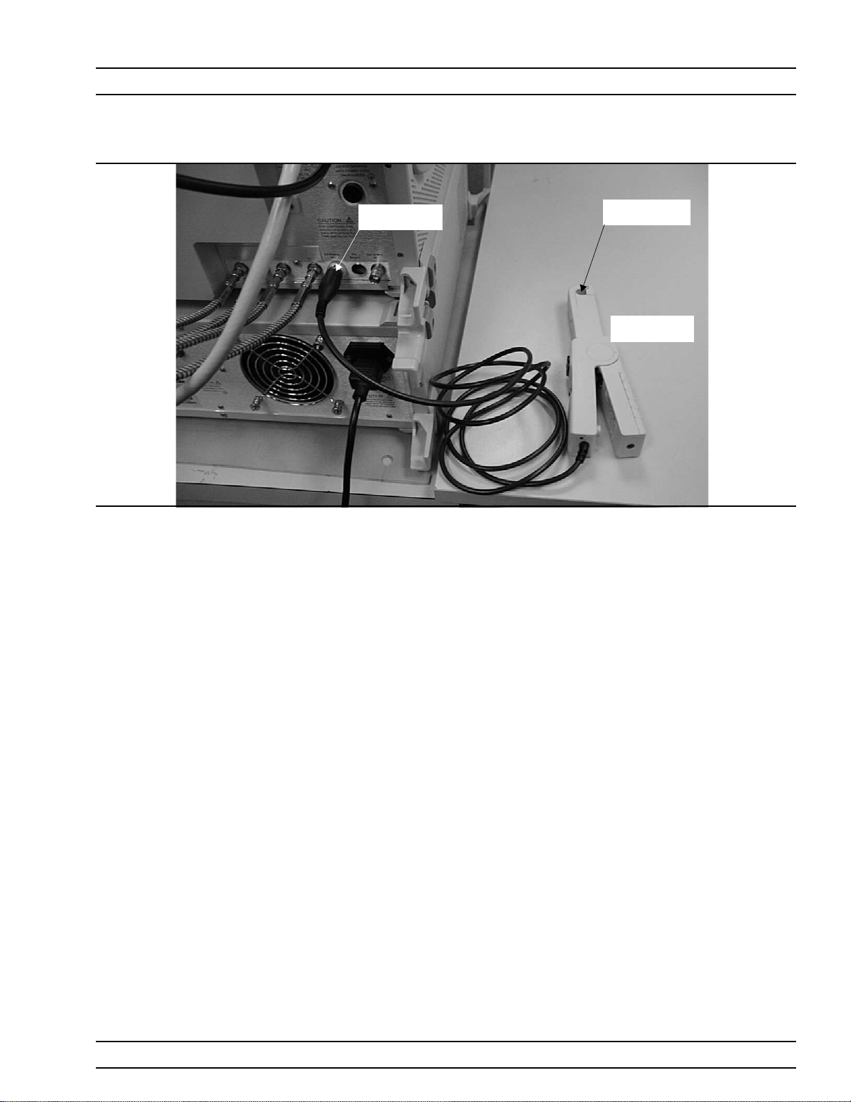
Step 7. (Optional, for drain current PAE measurements) Connect the
current probe cable BNC connector to the Ext. Analog In con
nector on the rear of the MS462XC as shown in Figure 2-4
(page 2-5).
2-4 ME 7840A OMM
-
-
Page 31
INSTALLATION INSTALLATION - HARDWARE
Figure 2-4. Current Probe Connection
EXTERNAL ANALOG
IN CONNECTOR
CURRENT SENSOR
CABLE PASSAGE
CURRENT PROBE
HEAD
ME7840A OMM 2-5
Page 32

INSTALLATION - HARDWARE INSTALLATION
Figure 2-5. Software Installation Window
2-6 ME 7840A OMM
Page 33

INSTALLATION INSTALLATION - SOFTWARE
2-5 INSTALLATION -
SOFTWARE
Installation Run the appropriate Setup.exe files to install Power Tools then the
What else is on the
CD?
ME7840A software is delivered on a CD. The ANRITSU Power Tools li
brary Version 4.0 or higher, which is required to be installed on the target
system (the PC which is receiving the installation of ME7840A software).
Power Tools Version 4.0 is also included in the ME7840A Software CD.
ME7840A software (Figure 2-5). During installation, the system may in
dicate that some files being installed already exist. In general it is best to
accept copying newer versions of files and reject copying older versions. If
in doubt, cancel the installation, backup the files in question, and try
again. The Readme.txt file lists the files and versions copied to the target
system during installation of ME7840A Software.
The system may also copy some files during ME7840A installation
andthen ask you to reboot. If this happens, reboot your Windows PC and
run the ME7840A Setup.exe program again after rebooting.
The CD includes a Readme.txt file in the root directory and two folders.
The readme file contains specific instructions for installing the software
and a listing of the features in the version being installed. The folders are
as follows:
q Power Tools Version 4.0 Installation files
q
PATS Installation Files
-
-
Uninstalling the
software
To uninstall ME7840A software or Power Tools go to the Windows Control
Panel and click on “Add/Remove Programs.” Select the programs you
would like to remove and follow instructions.
ME7840A OMM 2-7
Page 34

SERVICE CENTERS INSTALLATION
2-6 SERVICE CENTERS ANRITSU Service Centers are listed in Table 2-2.
Table 2-2. ANRITSU Service Centers
UNITED STATES
ANRITSU COMPANY
685 Jarvis Drive
Morgan Hill, CA 95037-2809
Telephone: (408) 776-8300
1-800-ANRITSU
FAX: 408-776-1744
ANRITSU COMPANY
10 New Maple Ave., Unit 305
Pine Brook, NJ 07058
Telephone: (201) 227-8999, 1-800-ANRITSU
FAX: 201-575-0092
ANRITSU COMPANY
1155E. Collins Blvd
Richardson, TX 75081
Telephone: 1-800-ANRITSU
FAX: 972-671-1877
AUSTRALIA
ANRITSU PTY. LTD.
Unit 3, 170 Foster Road
Mt Waverley, VIC 3149
Australia
Telephone: 03-9558-8177
FAX: 03-9558-8255
BRAZIL
ANRITSU ELECTRONICA LTDA.
Praia de Botafogo, 440, Sala 2401
CEP22250-040, Rio de Janeiro, RJ, Brasil
Telephone: 021-527-6922
FAX: 021-53-71-456
CANADA
ANRITSU INSTRUMENTS LTD.
215 Stafford Road, Unit 102
Nepean, Ontario K2H 9C1
Telephone: (613) 828-4090
FAX: (613) 828-5400
CHINA
ANRITSU BEIJING SERVICE CENTER
Beijing Fortune Building
1515, 5 Dong San Huan Bei Lu
Chaoyang qu, Beijing 100004, China
Telephone: 011861065909231
FAX: 011861065909235
FRANCE
ANRITSU S.A
9 Avenue du Quebec
Zone de Courtaboeuf
91951 Les Ulis Cedex
Telephone: 016-09-21-550
FAX: 016-44-61-065
GERMANY
ANRITSU GmbH
Grafenberger Allee 54-56
D-40237 Dusseldorf, Germany
Telephone: 0211-968550
FAX: 0211-9685555
INDIA
MEERA AGENCIES (P) LTD.
A-23 Hauz Khas
New Delhi 110016
Telephone: 011-685-3959
FAX: 011-685-2275
ISRAEL
TECH-CENT, LTD.
4 Raul ValenbergSt
Tel-Aviv 69719
Telephone: (03) 64-78-563
FAX: (03) 64-78-334
ITALY
ANRITSU Sp.A
Roma Office
Via E. Vittorini, 129
00144 Roma EUR
Telephone: (06) 50-99-711
FAX: (06) 50-22-4252
KOREA
ANRITSU CORPORATIONLTD.
14F, Hyunjuk Bldg
832-41 Yeoksam-Dong
Kangnam-Ku
Seoul South Korea 150 010
Telephone: 02-553-6603
FAX: 02-553-6604, 02-553-6605
JAPAN
ANRITSU CUSTOMER SERVICE LTD.
1800 Onna Atsugi-shi
Kanagawa-Prf. 243 Japan
Telephone: 0462-96-6688
FAX: 0462-25-8379
SINGAPORE
ANRITSU (SINGAPORE) PTE LTD.
6 New Industrial Road #06-01/02
Hoe Huat Industrial Bldg
Singapore 536199
Telephone: 282-2400
FAX: 282-2533
SOUTH AFRICA
ETECSA
12 Surrey Square Office Park
330 Surrey Avenue
Ferndale, Randburt, 2194
South Africa
Telephone: 011-27-11-787-7200
FAX: 011-27-11-787-0446
SWEDEN
ANRITSU AB
Botivid Center
Fittja Backe 1-3
S145 84 Stockholmn
Telephone: (08) 534-707-00
FAX: (08) 534-707-30
TAIWAN
ANRITSU CO., LTD.
6F, No. 96, Section 3
Chien Kuo N. Road
Taipei, Taiwan, R.O.C.
Telephone: (02) 515-6050
FAX: (02) 509-5519
UNITED KINGDOM
ANRITSU LTD.
200 Capability Green
Luton, Bedfordshire
LU1 3LU, England
Telephone: 015-82-4332003
FAX: 015-82-731303
2-8 ME 7840A OMM
Page 35

Chapter 3 Operations, General
3-1 INTRODUCTION The basic operation of the Model ME7840A Power Amplifier Test Station
(without external preamplifiers) is described in this and the following two
chapters: Calibration Operations and Measurement Operations. “Calibra
tion Operations” describes the software measurement calibration func
tion and “Measurement Operations” describes the software measurement
function. This chapter describes the setup and general operation of the
software. (See Chapter 7 for operation with external preamplifiers.)
-
-
3-2 PREPARING THE
SYSTEM
CAUTION
The AUT RF power output
maximum level should be
no more than the level
shown in the tabulation at
right. Otherwise, damage
to equipment will occur.
Refer to Figure 3-1 to identify the equipment named in the recommended
power-up sequence for the ME7840A.
Step 1. Connect the output of the AUT to Test Port 2 of the MS4782X.
Step 2. Connect the input of the AUT to Test Port 1 of the MS4782X.
Step 3. Ensure that the power rating of the cables is suitable for the
test, and that the connections are tightened.
Step 4. Turn on the MS462XC then the MS4782X Test Set.
Step 5. Set the output of the MS462XC so that the AUT output power
does not exceed the maximum Test Port 2 input level. See be
low.
Test Set Model
MS4782A Not Applicable 50 watts
MS4782D None (port C1 directly
MS4782D 1000-50 or 1000-52 (20
External Circulator
Used
connected to port C2)
dB isolation)
Test Port 2 Max Power
100 watts
50 watts
-
MS4782D 1000-53 (22 dB isolation) 79 watts
MS4782D Two circulators providing
greater than 23 dB
isolation
100 watts
ME7840A OMM 3-1
Page 36

PREPARING THE SYSTEM OPERATIONS, GENERAL
Step 6. When ready for measurements, cautiously apply DC power to
the AUT.
Step 7. Check that the normally factory-installed RF coaxial “jumper”
cable is installed on the rear panel of the Test Set:
MS4782X: Between Ext Preamp Input and Output
n
connectors.
MS4782D: Between connectors C1 and C2, unless a
n
circulator is installed.
Step 8. If drain current and/or PAE measurements are desired, the
optional current probe (ANRITSU part number 2000-1067 or
-1085) can be used. Ensure the probe (Figure 3-1) has a fresh
battery, and set the zero offset using the MS4623C as follows:
a.
Using Domain softkey, set to Transmission & Reflec
tion; using the Display soft key, set for Single Channel;
using the Graph Type softkey, set for Real; using the
Scale softkey and Data Entry keys, set for 1 mU/Division.
Use the Avg key and associated softkeys to set Aver-
aging for 10 and IF Bandwidth for 300 Hz. Use the
Config key, DATA POINTS and associated softkeys to
set for 101 Max Data Points.
-
b.
Use the Measure softkey and select Ext. Analog In.
c. Turn on the current probe and set it for the desired
range.
d. Adjust the “Zero Adjustment” thumbwheel until the
reading is minimum (typically 0 ±100mU).
e. On the current probe:
Orient the probe such that the “Current Direction”
arrow points away from the power supply.
Place the jaws only over the DC wire (not both wires)..
Unused Connections The EXT. SOURCE and AUX. OUT connectors must be terminated with
50W terminations when not in use.
3-2 ME 7840A OMM
Page 37

OPERATIONS, GENERAL PREPARING THE SYSTEM
Customer Supplied
Power Meter
for flat test port
power calibration
8
9
7
4
5
6
1
3
2
+/-
0
CLR
ON/ OFF
Channel
Sensor
Trigger
GPIB
System
Cal/ Zero
GPIB
Customer Supplied
System Controller (PC)
with GPIB
MS462X3C
DRA Scorpion
Port 3
Port 1
Port 2
To: Ext. Analog
In connector
MS4782A or D
CALIBRATOR
A
B
Port 3
50 Ohm Terminations
Port 1
Test
Port 1
Port 2
Test
Port 2
Sensor
Test Set
*
Customer Supplied
Input
Output
Power Supply
for AUT
Amplifier Under Test (AUT)
Optional
Current Probe
Connect when directed by procedure for power calibrations
*
Figure 3-1. PATS Power On Sequence
ME7840A OMM 3-3
Page 38

USING PATS SOFTWARE OPERATIONS, GENERAL
3-3 USING PATS
SOFTWARE
PATS software requires a computer with GPIB capability running Win
dows 95 or better (98/NT/2000). The software is started by selecting the
“Start” button, then “Programs,” “Pats V1.1,” then “Pats” (Figure 3-2).
-
Select “Pats” to start the
software
Select “Readme” to read the
description and any
late-breaking information
Select “Start” then “Programs” then “Pats V1.1”
Figure 3-2. Starting the PATS Software
Software
Organization
.
The PATS software has two main and three collateral functions. The two
main functions, calibration and measurement, are described in Chapters
3 and 4, respectively. The collateral functions, accessed from the PATS
program’s top menu, are described in paragraph 3-6.
about the software.
3-4 ME 7840A OMM
Page 39

OPERATIONS, GENERAL COLLATERAL FUNCTIONS
3-4 COLLATERAL
FUNCTIONS
File The file menu (below) provides for saving files from the PC to the
The PATS software collateral functions are found on the top menu bar un
der “Files,” “Tools,” and “Help.” (below)
Top Menu Bar
Same as File, Save
Files from PC
Same as File, Recall
Files to PC
MS462XC, recalling files from the MS462XC to the PC, and for exiting
the system.
-
Click on File to display a drop-down list (above) that provides the three
options described below. PATS Save and Recall functions have the exact
same behaviors as the Save/Recall button on the Scorpion. However, in
stead of saving to the Scorpion hard disk or recalling from the hard disk,
the PATS software allows users to Save to the PC’s hard disk and Recall
from the PC’s hard disk.
ME7840A OMM 3-5
Page 40

COLLATERAL FUNCTIONS OPERATIONS, GENERAL
Save Cal Files to PC. Displays a dialog box (similar to that shown
q
for Recall Cal Files from PC, below) showing the cal files stored in
the default folder (Temp). This function is useful for saving the
front panel setup and calibration data to a file on the PC. The user
has the option of overwriting an existing file by selecting an exist
ing file from the file listing or creating a new file by typing in a file
name. The user must type in a “.cal” extension or the program will
report an error. The calibration procedure automatically saves cal
files to the PC. The file names of these files is specified in the cali
bration specification file (*.txt file).
Recall Cal Files from PC: Displays a dialog box similar to that
q
shown below with the listing of file name. This function transfers a
.cal file from the PC to the Scorpion over the GPIB bus (and names
the file a.cal on the Scorpion’s hard disk) and then recalls the front
panel setup and cal data from a.cal.
-
-
q
Exit: Exits the PATS software.
Help The “Help” function is not available in the current software. It will be
available in future software versions.
3-6 ME 7840A OMM
Page 41

OPERATIONS, GENERAL COLLATERAL FUNCTIONS
Tools The “Tools” menu (below) displays a drop-down list that provides three
collateral options described below. The “Run Calibration Files” option is
described in Chapter 4.
a. Check Communications to VNA: Runs a test to check
that the VNA communicates with the PC. Run this option first to ensure that the PATS setup is correct and
functioning properly. If so, a dialog box appears like that
shown below.
ME7840A OMM 3-7
Page 42

COLLATERAL FUNCTIONS OPERATIONS, GENERAL
b. Calibration File Options: Provides options for finding
and recalling calibration files (below). These files are
used to establish test setup for the measurements de
scribed in Chapter 5. If no file is selected in an area (S
Parameter, Power Sweep, IMD, etc., the associated mea
surement will assume the PATS default setting. Clicking
on “Find and Recall” button will display the list of files
as was shown for “File”, Step 1a, above. Clicking on a
filename will cause it to display in the associated win
dow in this screen.
-
-
-
c. Limits: Provides for setting limts for S-Parameter mea-
surements.
3-8 ME 7840A OMM
Page 43

Chapter 4 Operations, Calibration
4-1 INTRODUCTION Measurements always include a degree of uncertainty due to imperfec
tions in the measurement system. The measured value is always a combi
nation of the actual value plus the systematic measurement errors. Cali
bration, as it applies to network analysis, characterizes the systematic
measurement errors and subtracts them from the measured value to ob
tain the actual value. Each of the ME7840A measurements requires a cal
ibration to account for measurement uncertainties. This chapter de
scribes the measurement calibration operations of the Model ME7840A
Power Amplifier Test System software.
4-2 OPERATION,
GENERAL
Refer to Chapter 3 for general operation and setup of the ME7840A.
-
-
4-3 PROGRAM FILES The PATS software sets up the MS462XC DRA Scorpion according to in-
structions in the “Calibration Specification” files, which are accessed from
the “Tools,” “Run Calibration Procedure” function that is described later
in this chapter. These are user-editable text files that establish the conditions during calibration and measurement. How to edit these files is described in Appendix A.
The calibration data and Scorpion switch settings that result from follow
ing a “Run Calibration Procedure” specification file are saved as a *.cal
file. These *.cal files are accessed using the “Tools,” “Calibration File Op
tion” function that was described in paragraph 3-6, page 3-8. When one
of these files is recalled using the “Calibration File Option,” the Scorpion
is ready to acquire correct (calibrated) measurements.
-
-
-
-
-
-
Examples of instrument settings / conditions that reside in the Calibra
tion Specification files include:
q
Sweep start and stop frequencies
q
Number of data points
q
Source 1 and 2 power levels
q
Scorpion IF bandwidth
q
Averaging
q
Scorpion display settings
Some of these parameters can also be specified / modified by the User In
put window before each actual measurement so long as such modification
is consistent with the calibration to be applied.
-
-
ME7840A POM 4-1
Page 44

TEST EQUIPMENT OPERATIONS, CALIBRATION
Alternatively, Scorpion front panel settings may be set manually and ap
plied during the automated measurements under PATS software as fol
lows:
On the Measurement Window click the Pause button
q
On the Scorpion front panel press the “Clr / Local” button to take
q
manual control of the Scorpion.
Use Scorpion front panel controls to set the desired settings and/or
q
to perform a new calibration. (Note: Unless a new calibration is per
formed, the manual settings must be consistent with the calibration
to be applied).
Use the “Save Cal File to PC.” (Refer to Appendix A for detailed in
q
formation on how to use the “Calibration Specification Files.”
-
4-4 TEST EQUIPMENT A power meter, power sensor, and Type N calibration component kit is re
quired for power level and S-parameters calibrations. See Table 1-2, page
1-12.
-
-
-
-
4-2 ME 7840A POM
Page 45

OPERATIONS, CALIBRATION GENERAL
4-5 GENERAL Calibration operations are described in this and the following paragraphs
Step 1. Click on “Start,” “Programs,” “Pats V1.1,” then “Pats” (Figure
3-2, page 3-4) to start the software.
The PATS flash screen (below) briefly appears, then the main
screen.
The main screen (below) provides access to all software options.
Step 2. Click on “Tools” then “Check Communications to VNA” to en
-
ME7840A OMM 4-3
Page 46

POWER LEVEL OPERATIONS, CALIBRATION
sure that the equipment is properly connected to the bus. If
so, the following screen will be displayed:
Step 3. Click on “Run Calibration Procedure” to display a list of cali
bration specification files (below). (Refer to paragraph 4-3 for
a description of these files.) Running the files is described in
succeeding numbered paragraphs.
4-6 POWER LEVEL The A_Power Level.txt specification file provides prompts for a power
level calibration. Proceed as follows:
-
Step 1. Zero-set the power sensor for accurate measurement in fol
lowing steps.
Step 2. Select “Tools” then “Run Calibration Procedure.”
-
4-4 ME 7840A OMM
Page 47

OPERATIONS, CALIBRATION POWER LEVEL
Step 3. Double-click on “A_Power Level.txt.” . The program starts
with a linear power calibration (below).
Step 4. Before hitting the “Next” button, connect the power meter to
at the point where power enters the device-under-test (AUT),
which becomes the power reference plane as shown in the
prompt.
The use of cables and/or adapters does not effect the final
measurement result, if they are in place for the calibration pro
cess. The vector error corrections established during the cali
bration process eliminates cable and/or adapter effects as long
as the ports used are stable and exhibit good repeatability,
which is the case if good quality components are used.
Many calibration kits include adapters that are designed to
have equal phase length. These parts are called phase equal
adapters (PEA). ANRITSU designs in-series adapters (e.g.,
SMA Connector M-M, M-F, F-F) to be phase insertable when
technically possible.
-
ME7840A OMM 4-5
-
Page 48

POWER LEVEL OPERATIONS, CALIBRATION
NOTE
The linear power calibration takes up-to-5 minutes to
complete. It calibrates the output power at the refer
ence plane for both internal sources (power out of
Port 1 then Port 3) according to the target power
across the frequency range set in the calibration speci
fication file. When the test completes, the “Next” but
ton will become available.
Step 5. Press “Next” to calibrate flat power response (below).
-
-
-
NOTE
The flat power calibration also takes less than 1 min
ute to complete. It calibrates the output power at the
reference plane for both internal sources (power out
of Port 1 then Port 3) according to the target power
across the frequency range set in the calibration speci
fication file. When the test completes, the “Next” but
ton will become available.
-
-
-
4-6 ME 7840A OMM
Page 49

OPERATIONS, CALIBRATION POWER LEVEL
Step 6. Before pressing “Next” disconnect the power sensor and con
nect a throughline between Test Ports 1 and 2 on the
MS4782X Test Set, as shown below.
-
Step 7. Press “Next” to perform a receiver calibration. When this cali
bration finishes, the program returns to the main screen.
ME7840A OMM 4-7
-
Page 50

HOT S22 OPERATIONS, CALIBRATION
4-7 HOT S22 The “B_HotS22.txt” file provides prompts for setting up a Hot S
cation file. Hot S
port (Port 2) while stimulus is applied to its input port. The prompts
cause the Scorpion to be placed into a state where it is ready to make cali
brated measurements on the user’s AUT. At the completion of the pro
gram, the state information is saved to a *.cal file. To run this program,
proceed as follows.
Step 1. Select “Tools” then “Run Calibration Procedure.”
Step 2. Double-click on “C_Hot S22.txt” to begin the Hot S
setup. Follow the prompt and connect open, short, and load to
Port 2 as directed.
is a return loss measurement of an amplifier’s output
22
specifi
22
cal file
22
-
-
-
4-8 ME 7840A OMM
Page 51

OPERATIONS, CALIBRATION HOT S22
Step 3. Press “Next” for the next prompt (below). The 3653 or 3753LF
Calibration Kits contain a disk with calibration data. The
data has to be installed from the MS462C front panel. To do
so, place the floppy disk from the kit into the MS462XC disk
drive. Press the Cal key then COMPONENTS UTILITIES/IN
STALL KIT INFO FROM FLOPPY DISK. softkeys.
Step 4. Press “OK” for the next step (below). Connect the Open to
Port 2.
-
Step 5. Press “OK” for the next step (below). Connect the Short to
Port 2.
ME7840A OMM 4-9
Page 52

HOT S22 OPERATIONS, CALIBRATION
Step 6. Press “OK” for the next step (below). Connect the Load to Port
2.
Step 7. Press “OK” to complete the Hot S
calibration.
22
4-10 ME 7840A OMM
Page 53

OPERATIONS, CALIBRATION S-PARAMETERS CAL
4-8 S-PARAMETERS
CAL
The “C_S-Parameters Cal.txt” file to provides prompts for setting up
S-parameters specification file. The prompts cause the Scorpion to be
placed into a state where it is ready to make calibrated measurements on
the user’s AUT. At the completion of the program, the state information is
saved to a *.cal file. To run this program, proceed as follows.
Step 1. Select “Tools” then “Run Calibration Procedure.”
Step 2. Double-click on “D_S Parameters.txt” to begin the file
setup.Follow the prompt and connect open, short, and load to
Ports 1 and 2 as directed.
ME7840A OMM 4-11
Page 54

S-PARAMETERS CAL OPERATIONS, CALIBRATION
Step 3. Press “Next” for the next step (below). The 3653 or 3753LF
Calibration Kits contain a disk with calibration data. The
data has to be installed from the MS462C front panel. To do
so, place the floppy disk from the kit into the MS462XC disk
drive. Press the Cal key then COMPONENTS UTILITIES/IN
STALL KIT INFO FROM FLOPPY DISK softkeys.
Step 4. Press “OK” for the next step (below). Connect the Broadband
Load on Test Ports 1 and 2 on the ME7840A Test Set.
Step 5. Press “OK” for the next step (below). Connect the Open to
Test Port1 and the Short to Test Port 2.
-
4-12 ME 7840A OMM
Page 55

OPERATIONS, CALIBRATION S-PARAMETERS CAL
Step 6. Press “OK” for the next step (below). Connect the Short to
Test Port 1 and the Open to Test Port 2.
Step 7. Press “OK” for the next step (below). Connect the Throughline
between Test Ports 1 and 2.
ME7840A OMM 4-13
Page 56

S-PARAMETERS CAL OPERATIONS, CALIBRATION
Step 8. Press “OK” to complete the S Parameters calibration (below).
4-14 ME 7840A OMM
Page 57

OPERATIONS, CALIBRATION CAL FILE SETUP
4-9 CAL FILE SETUP The “D_Cal File Setup.txt” file provides prompts for setting up One-tone
power sweep, IMD, Two-Tone Power Sweep, and Harmonic specification
file. The prompts cause the Scorpion to be placed into a state where it is
ready to make calibrated measurements on the user’s AUT. At the com
pletion of the program, the state information is saved to a *.cal file. To
run this program, proceed as follows.
Step 1. Select “Tools” then “Run Calibration Procedure.”
Step 2. Double-click on “B_Cal Files Setup.txt.” to begin with the file
setup for a Transmission Frequency Response (S
One-Tone Power Sweep. Connect a throughline when di
rected in a following step.
cal) for
21
-
-
ME7840A OMM 4-15
Page 58

CAL FILE SETUP OPERATIONS, CALIBRATION
Step 3. Press “Next” for the next prompt (below). The 3653 or 3753LF
Calibration Kits contain a disk with calibration data. The
data has to be installed from the MS462C front panel. To do
so, place the floppy disk from the kit into the MS462XC disk
drive. Press the Cal key then COMPONENTS UTILITIES/IN
STALL KIT INFO FROM FLOPPY DISK. softkeys. Press OK
when ready to proceed.
Step 4. Connect the Throughline between Test Ports 1 and 2 on the
MS4782X Test Set.
-
4-16 ME 7840A OMM
Page 59

OPERATIONS, CALIBRATION CAL FILE SETUP
Step 5. Press “OK” to continue to the IMD cal file setup prompt (be
low). Follow the prompt and connect a throughline between
Test Ports 1 and 2 on the MS4782X Test Set.
-
ME7840A OMM 4-17
Page 60

CAL FILE SETUP OPERATIONS, CALIBRATION
Step 6. Press “Next” to begin the Power Sweep cal file setup (below).
4-18 ME 7840A OMM
Page 61

OPERATIONS, CALIBRATION CAL FILE SETUP
Step 7. Press “Next” to perform Harmonic Cal File Setup calibration
(below).
Step 8. Press “Next” to end the calibration and return to the main
screen.
ME7840A OMM 4-19/4-20
Page 62

Chapter 5 Operations, Measurement
5-1 INTRODUCTION This chapter describes the five measurements available with the
ME7840A software: S-Parameters, Power Sweep, IMD (intermodulation
distortion), Harmonics, and Hot S
22
.
5-2 OPERATION,
GENERAL
5-3 MEASUREMENT
CALIBRATION
Refer to Chapter 3 for general operation and setup of the ME7840A.
Measurements always include a degree of uncertainty due to imperfec
tions in the measurement system. The measured value is always a combination of the actual value plus the systematic measurement errors. Calibration, as it applies to network analysis, characterizes the systematic
measurement errors and subtracts them from the measured value to obtain the actual value. Each of the ME7840A measurements requires a calibration to account for measurement uncertainties. Refer to Chapter 4 for
measurement calibration procedures.
-
5-4 GENERAL Measurements can be approached from two directions: calibration(s) com-
pleted, calibration(s) not completed.
Calibration(s)
Completed
Proceed as follows:
Step 1. Click on “Tools,” and open “Check Communications to VNA.”
Step 2. Verify the communications are correct.
Step 3. Click on “Tools,” and open “Calibration File Options.”
Step 4. Click on “Find and Recall” and recall a *.cal file for each mod
ule. Filenames are listed below and shown in graphic below
last listing.
-
n
S Parameters: “S_Parameters_1.cal”
n
Power Sweep (2T): “PowSweep_1.cal”
n
Power Sweep (1T): “PSweep1T_1.cal”
n
C3, IMD: “Imd_1.cal”
n
C4, Harmonics: “Harmonics_1.cal”
ME7840A OMM 5-1
Page 63

GENERAL OPERATIONS, MEASUREMENT
C5, Hot S
n
Step 5. Select appropriate file “Open” (below).
¾ “Hots22_1.cal”
22
Calibration(s) Not
Completed
Sometimes users may wish to run a measurement using default settings,
that is, without spending the time required to calibrate. The procedure
below gives instructions.
Step 1. Click on “Tools,” and open “Check Communications to VNA.”
Step 2. Verify the communications are correct.
Step 3. Click on “Tools,” and open “Calibration File Options.”
Step 4. Clear the text for all modules then select “Return.”
Step 5. Press any measurement button on main menu and measure
ment will be run using “PATS software” default values: Cali
bration Off on MS462XC and MS462XC Default parameters
in place. The default values are shown below.
-
-
5-2 ME 7840A OMM
Page 64

OPERATIONS, MEASUREMENT GENERAL
D1, S-Parameters and Hot S
n
Points = 201
ü
Start Frequency = 800 MHz
ü
Stop Frequency = 2400 MHz
ü
Input Power=0dB
ü
D2, Power Sweep (2 tone power sweep)
n
Main Tone = 950 MHz
ü
Offset = 971 kHz
ü
Start Power = -15 dBm
ü
Stop Power=0dBm
ü
Data Points = 21
ü
D3, IMD
n
Main Tone = 900 MHz
ü
ü Offset Frequency = 977 kHz
ü Input Power=0dBm
ü IMD Order = 9
n D4, Harmonics
ü Start Frequency = 100 MHz
ü Stop Frequency = 3000 MHz
ü Main Tone = 800 MHz
ü Input Power=0dBm
22
ME7840A OMM 5-3
Page 65

S-PARAMETERS OPERATIONS, MEASUREMENT
5-5 S-PARAMETER TESTS:
S
21,S11,S22,S12
, ALL
This test measures the scattering parameters (S-parameters). The test
module comprises six tests: S11,S12,S21,S22, and ALL. (The K Factors
test is described in paragraph 5-6.) In each case, the measurement
screens are the similar. This procedure will present a test screen for the
“S
” measurement and will describe certain differences at the end of the
21
procedure.
Procedure.
Prepare the ME7840A as shown in Chapter 3.
Enter the appropriate test values in the displayed
User Input screen. The input fields are described
below: The inputs required for this test are de
-
scribed below.
S-Parameter: Drop down options. Set to S21for
n
this procedure. Other selections include S
S
, ALL, and K Factor (paragraph 5-6).
22
Data Points: Drop down options - number of data
n
11,S12
points in frequency sweep.
Frequency 1 (MHz): Lower frequency or start fre-
n
quency.
n
Frequency 2 (MHz): Upper frequency or stop fre-
quency.
n
Input Power (dBm):Input power level, in dBm.
n
IF Bandwidth (Hz):Intermediate frequency band-
width for test, in Hertz.
n
Test Set Setting: Byte value for setting test set
attenuation and source switch (below).
,
Internal Source Value External Source Value
0dB 8 0dB 0
10 dB 9 10 dB 1
20 dB 10 20 dB 2
30 dB 11 30 dB 3
40 dB 12 40 dB 4
50 dB 13 50 dB 5
60 dB 14 60 dB 6
70 dB 15 70 dB 7
5-4 ME 7840A OMM
Page 66

OPERATIONS, MEASUREMENT S-PARAMETERS
Select Start Test: Observe that the test screen
n
(Figure 5-1) appears.
Figure 5-1. S-Parameters Test Screen for S
21
Button Panel Options:
q
Print: Prints a copy of the screen graphic to a
printer.
q
Write Data: Two data files are written to the
C:\Program Files\Pats\Datafiles folder; the
file name will have a time stamp. One datafile
has a “.csv” file extension and the other has a
“.s2p” file extension. For example:
“S17-16-19-29.csv (and s2p)” was created on
the 17th day of the month at 4:19 PM and 49
seconds. CSV and S2P files are comma sepa
rated text and can be opened in the Windows
Microsoft Excel spreadsheet.
q
Upper Limit/Lower Limit: Limit values as
set using Tools menus (Chapter 4).
q
Return: Returns to the main PATS screen.
ME7840A OMM 5-5
Page 67

S-PARAMETERS OPERATIONS, MEASUREMENT
Change Params: Returns to User Input
q
screen.
Autoscale Checkbox: Turns autoscale on or
q
off. Autoscale automatically scales the mea
surement results.
Reset/Zoom: Disabled for this test.
q
Max/Min: Type in maximum and minimum
q
display value. Use Rescale after changing val
ues.
Rescale: Rescales the measurement results.
q
-
-
Markers Screen Options for S
M1: Turnsmarker on or off (checked or un
q
11,S21,S12,S22
checked). If on: Slider moves marker between
data points, and window below displays marker
frequency and amplitude values amplitude
value at the marker.
M2: Same as above.
q
M3: Same as above.
q
M4: Same as above.
q
Markers Screen Options for ALL (left):
q
Marker Slider: Moves marker between data
points.
q
Frequency Display: Displays marker fre
quency.
q
S11: S11input return loss.
q
S21: S21gain.
q
S12: S12output isolation.
q
S22: S22output return loss.
(left):
-
-
5-6 ME 7840A OMM
Page 68

OPERATIONS, MEASUREMENT S-PARAMETER TEST: K FACTOR
5-6 S-PARAMETER
TEST: K FACTOR
This test describes the K Factors measurement. This measurement is
described in Chapter 1, paragraph 1-10.
Procedure.
Prepare the ME7840A as shown in Chapter 3.
Enter the appropriate test values in the displayed
User Input screen. The input fields are described
below: The inputs required for this test are de
-
scribed below.
S-Parameter: Drop down options. K Factor for
n
this measurement.
Data Points: Drop down options - number of data
n
points in frequency sweep.
Frequency 1 (MHz): Lower frequency or start fre-
n
quency.
Frequency 2 (MHz): Upper frequency or stop fre-
n
quency.
Input Power (dBm):Input power level, in dBm.
n
n
IF Bandwidth (Hz):Intermediate frequency band-
width for test, in Hertz.
n
Test Set Setting: Byte value for setting test set
attenuation and source switch (below).
Internal Source Value External Source Value
0dB 8 0dB 0
10 dB 9 10 dB 1
20 dB 10 20 dB 2
30 dB 11 30 dB 3
40 dB 12 40 dB 4
50 dB 13 50 dB 5
60 dB 14 60 dB 6
70 dB 15 70 dB 7
ME7840A OMM 5-7
Page 69

S-PARAMETER TEST: K FACTOR OPERATIONS, MEASUREMENT
Select Start Test: Observe that the test screen
n
(Figure 5-1) appears.
Figure 5-2. S-Parameters Test Screen for S
21
Button Panel Options:
q
Print: Prints a copy of the screen graphic to a
printer.
q
Write Data: Two data files are written to the
C:\Program Files\Pats\Datafiles folder; the
file name will have a time stamp. One datafile
has a “.csv” file extension and the other has a
“.s2p” file extension. For example:
“S17-16-19-29.csv (and s2p)” was created on
the 17th day of the month at 4:19 PM and 49
seconds. CSV and S2P files are comma sepa
rated text and can be opened in the Windows
Microsoft Excel spreadsheet.
q
Upper Limit/Lower Limit: Limit values as
set using Tools menus (Chapter 4).
q
Return: Returns to the main PATS screen.
5-8 ME 7840A OMM
Page 70

OPERATIONS, MEASUREMENT S-PARAMETER TEST: K FACTOR
Change Params: Returns to User Input
q
screen.
Autoscale Checkbox: Turns autoscale on or
q
off. Autoscale automatically scales the mea
surement results.
Reset/Zoom: Disabled for this test.
q
Max/Min: Type in maximum and minimum
q
display value. Use Rescale after changing val
ues.
Rescale: Rescales the measurement results.
q
Markers Screen Options for K Factor (left):
Marker Slider: Moves marker between data
q
points.
Frequency Display: Displays marker fre
q
quency.
KF: Displays the K factor value. K factor is a
q
stability factor of interest for amplifier designers.
-
-
-
ME7840A OMM 5-9
Page 71

S-PARAMETERS OPERATIONS, MEASUREMENT
5-7 POWER SWEEP, TWO
TONE
Single Frequency
Power Sweep
This measurement module has three variations of possible Measurement
Types: Power Sweep (single frequency), Multi Frequency Power Sweep,
Gain and IMD.
Procedure.
Prepare the ME7840A as shown in Chapter 3.
Enter the appropriate test values in the displayed
User Input screen. The input fields are described
below:
Measurement Type: Drop down options showing
n
Power Sweep (single frequency), Multi Freq Power
Sweep (uses 3 frequencies), Gain & IMD. Set to
“Power Sweep ” for this test.
Main Tone (MHz): CW Frequency setting for
n
source 1.
Offset (kHz): Offset frequency for Source 2
n
(Source 2 will be set to Main Tone + Offset).
n
Start Power (dBm): Power will be swept starting
at the start power (input RF power to AUT). Both
sources are simultaneously set to each power setting. The stop power is also entered in the “to”
window.
n
Data Points: Number of data points in power
sweep.
n
Increment Power (dBm): Value to increment
power for each data point (calculated and dis
-
played only).
n
Source Attn (dB):Value of Source attenuation, be
tween 0 and -70 (calculated and displayed only).
n
Drain Current Checkbox: When checked the
drain current is measured and power added effi
-
ciency is calculated and displayed.
n
PStop Level (dB):Provides the ability to set the
PStop value based on the level of gain compres
sion. Drop down options include compression levels
of 1 dB through 10 dB in 1 dB increments, and
OFF. If OFF is selected, then the P Stop equals the
value entered in the “to” window above. If the se
lected compression occurs, PStop for all subse
quent power sweeps is reset to one increment be
fore the P
value where this compression level is
in
-
-
-
reached.
-
5-10 ME 7840A OMM
Page 72

OPERATIONS, MEASUREMENT POWER SWEEP, TWO TONE
Test Set Setting: Byte value for setting test set
n
attenuation and source switch (below).
Internal Source Value External Source Value
0dB 8 0dB 0
10 dB 9 10 dB 1
20 dB 10 20 dB 2
30 dB 11 30 dB 3
40 dB 12 40 dB 4
50 dB 13 50 dB 5
60 dB 14 60 dB 6
70 dB 15 70 dB 7
ME7840A OMM 5-11
Page 73

POWER SWEEP, TWO TONE OPERATIONS, MEASUREMENT
Select Start Test and observe that the test screen
(Figure 5-3) appears.
Figure 5-3. Single Frequency Power Sweep Test
Button Panel Options:
q
Print: Prints a copy of the screen graphic to a
printer.
q
Write Data: Excel data is written to C:\Pro
gram Files\Pats\Datafiles - the file name will
have a time stamp. For example:
“S17-16-19-29.csv” was created on the 17th day
of the month at 4:19 PM and 49 seconds. CSV
files are comma separated text and can be
opened iin Windows Excel.
q
Pause/Go: Stops data transfer from VNA to
PC and places MS4623C in “Local” mode.
q
Return: Returns to the main PATS screen.
q
Change Params: Returns to User Input
screen.
5-12 ME 7840A OMM
Page 74

OPERATIONS, MEASUREMENT POWER SWEEP, TWO TONE
Autoscale Checkbox: Turns autoscale on or
q
off. Autoscale automatically scales the mea
surement results.
Reset/Zoom: Disabled for this test.
q
Max/Min: Type in maximum and minimum
q
display value. Use Rescale after changing val
ues.
Rescale: Rescales the measurement results.
q
Pause/Go: Pause stops data transfer from
q
VNA to PC and places MS462XC in “Local”
mode. Go starts data transfer to MS462XC in
“Remote” mode.
Markers Screen Options (left):
Markers slider: Moves marker between data
q
points.
Power In Reading: Indicates the input power
q
value.
Pout F1: Power output at frequency 1.
q
Pout F2: Power output at frequency 2.
q
q IM3U: Intermodulation product 3 upper side-
band
q
IM3L:Intermodulation product 3 lower sideband
q
IM5U:Intermodulation product 5 upper sideband
q
IM5L:Intermodulation product 5 lower side
band
q
IM7U:Intermodulation product 7 upper side
band
q
IM7L:Intermodulation product 7 lower side
band
q
PAE: Power-added efficiency percentage.
q
Drain: Drain current value.
-
-
-
-
-
NOTE
PAE and Drain may be on or off according to check
box in parameter screen.
ME7840A OMM 5-13
Page 75

POWER SWEEP, TWO TONE OPERATIONS, MEASUREMENT
Multiple Frequency
Power Sweep
Procedure.
Measurement Type: Drop down options. Set to
n
“Multi Freq Power Sweep ” for this test.
Main Tone (MHz): CW Frequency setting for
n
source 1. The user may set a lower tone and upper
tone. The software will sweep three frequencies
(the two input plus one between) and the RF input
power to produce the display data.
Offset (kHz): Offset frequency for Source 2
n
(Source 2 will be set to Main Tone + Offset).
Start Power (dBm): Power will be swept starting
n
at the start power (input RF power to AUT). Both
sources are simultaneously set to each power set
ting. The stop power is also entered in the “to” win
dow.
Data Points: Number of data points in power
n
sweep.
Increment Power (dBm): Value to increment
n
power for each data point (calculated and displayed only).
n
Source Attn (dB):Value of Source attenuation, be-
tween 0 and -70 (calculated and displayed only).
n
Drain Current Checkbox: When checked the
drain current is measured and power added efficiency is calculated and displayed.
n
PStop Level (dB):Provides the ability to set the
PStop value based on the level of gain compres
sion. Drop down options include compression levels
of 1 dB through 10 dB in 1 dB increments, and
OFF. If OFF is selected, then the P Stop equals the
value entered in the “to” window above. If the se
lected compression occurs, PStop for all subse
quent power sweeps is reset to one increment be
fore the P
value where this compression level is
in
reached.
-
-
-
-
-
-
5-14 ME 7840A OMM
Page 76

OPERATIONS, MEASUREMENT POWER SWEEP, TWO TONE
Test Set Setting: Byte value for setting test set
n
attenuation and source switch (below).
Internal Source Value External Source Value
0dB 8 0dB 0
10 dB 9 10 dB 1
20 dB 10 20 dB 2
30 dB 11 30 dB 3
40 dB 12 40 dB 4
50 dB 13 50 dB 5
60 dB 14 60 dB 6
70 dB 15 70 dB 7
ME7840A OMM 5-15
Page 77

POWER SWEEP, TWO TONE OPERATIONS, MEASUREMENT
Select Start Test. Observe that the test screen (Fig
ure 5-4) appears.
-
Figure 5-4. Multiple Frequency Power Sweep Test
Button Panel Options:
q
Print: Prints a copy of the screen graphic to a
printer.
q
Write Data: Excel data is written to C:\Pro
gram Files\Pats\Datafiles - the file name will
have a time stamp. For example:
“S17-16-19-29.csv” was created on the 17th day
of the month at 4:19 PM and 49 seconds. CSV
files are comma separated text and can be
opened iin Windows Excel.
-
5-16 ME 7840A OMM
Page 78
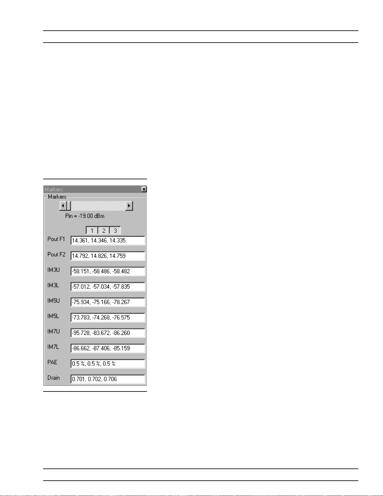
OPERATIONS, MEASUREMENT POWER SWEEP, TWO TONE
Pause/Go: Stops data transfer from VNA to
q
PC and places MS4623C in “Local” mode.
Return: Returns to the main PATS screen.
q
Change Params: Returns to User Input
q
screen.
Y1, Y2: Provides for rescaling the left or right
q
axis.
Rescale: Rescales the measurement results.
q
Max/Min: Type in maximum and minimum
q
display value. Use Rescale after changing val
ues.
Markers Screen Options (left):
Markers slider: Moves marker between data
q
points.
Pout F1: Power output at frequency 1.
q
Pout F2: Power output at frequency 2.
q
IM3U: Intermodulation product 3 upper side-
q
band
IM3L:Intermodulation product 3 lower side-
q
band
q
IM5U:Intermodulation product 5 upper sideband
q
IM5L:Intermodulation product 5 lower sideband
q
IM7U:Intermodulation product 7 upper side
band
q
IM7L:Intermodulation product 7 lower side
band
q
PAE: Power-added efficiency percentage.
q
Drain: Drain current value.
-
-
-
ME7840A OMM 5-17
Page 79

POWER SWEEP, TWO TONE OPERATIONS, MEASUREMENT
Gain and IMD Power
Sweep
Procedure:
Measurement Type: Drop down options. Set to
n
“Gain and IMD ” for this test.
Main Tone (MHz): CW Frequency setting for
n
source 1.
Offset (kHz): Offset frequency for Source 2
n
(Source 2 will be set to Main Tone + Offset)
Start Power (dBm): Power will be swept starting
n
at the start power (input RF power to AUT). Both
sources are simultaneously set to each power set
ting. The stop power is also entered in the “to” win
dow.
Data Points: Number of data points in power
n
sweep.
Increment Power (dBm): Value to increment
n
power for each data point (calculated and displayed only).
n Source Attn (dB):Value of Source attenuation, be-
tween 0 and -70 (calculated and displayed only).
n
Drain Current Checkbox: When checked the
drain current is measured and power added efficiency is calculated and displayed.
n
PStop Level (dB):Provides the ability to set the
PStop value based on the level of gain compres
sion. Drop down options include compression levels
of 1 dB through 10 dB in 1 dB increments, and
OFF. If OFF is selected, then the P Stop equals the
value entered in the “to” window above. If the se
lected compression occurs, PStop for all subse
quent power sweeps is reset to one increment be
fore the P
value where this compression level is
in
-
-
-
reached.
-
5-18 ME 7840A OMM
Page 80

OPERATIONS, MEASUREMENT POWER SWEEP, TWO TONE
Test Set Setting: Byte value for setting test set
n
attenuation and source switch (below).
Internal Source Value External Source Value
0dB 8 0dB 0
10 dB 9 10 dB 1
20 dB 10 20 dB 2
30 dB 11 30 dB 3
40 dB 12 40 dB 4
50 dB 13 50 dB 5
60 dB 14 60 dB 6
70 dB 15 70 dB 7
ME7840A OMM 5-19
Page 81

POWER SWEEP, TWO TONE OPERATIONS, MEASUREMENT
Select Start Test. Observe that the test screen (Fig
ure 5-5) appears.
-
Figure 5-5. Power Sweep Gain and IMD Test Screen, with Markers Selected
Button Panel Options:
q
Print: Prints a copy of the screen graphic to a
printer.
q
Write Data: Excel data is written to C:\Pro
gram Files\Pats\Datafiles - the file name will
have a time stamp. For example:
“S17-16-19-29.csv” was created on the 17th day
of the month at 4:19 PM and 49 seconds. CSV
files are comma separated text and can be
opened iin Windows Excel.
q
Pause/Go: Stops data transfer from VNA to
PC and places MS4623C in “Local” mode.
5-20 ME 7840A OMM
Page 82

OPERATIONS, MEASUREMENT POWER SWEEP, TWO TONE
Return: Returns to the main PATS screen.
q
Change Params: Returns to User Input
q
screen.
Y1, Y2: Provides for rescaling the left or right
q
axis.
Rescale: Rescales the measurement results.
q
Max/Min: Type in maximum and minimum
q
display value. Use Rescale after changing val
ues.
Markers Screen Options (left):
Markers slider: Moves marker between data
q
points.
Gain dB: Gain (or S21) is measured at each
q
CW tone as the power is swept The measure
ment is made in IMD mode. The Gain is actu
ally measured by calculating the difference between Power In (in dBm) and Power Out (in
dBm). Calibration applied is Linear Power Cal
and Receiver Cal. (Could also be called Gain
and compression measurement). The displayed
Power In level is the power of each input tone.
q
Gain dB: See above.
q
IM3U: Intermodulation product 3 upper sideband
q
IM3L:Intermodulation product 3 lower sideband
q
IM5U:Intermodulation product 5 upper side
band
q
IM5L:Intermodulation product 5 lower side
band
q
IM7U:Intermodulation product 7 upper side
band
q
IM7L:Intermodulation product 7 lower side
band
q
PAE: Power-added efficiency percentage.
q
Drain: Drain current value.
-
-
-
-
-
-
-
ME7840A OMM 5-21
Page 83

POWER SWEEP, ONE TONE OPERATIONS, MEASUREMENT
5-8 POWER SWEEP, ONE
TONE
Single Frequency
Power Sweep
This measurement module has three variations of possible Measurement
Types: Power Sweep (single frequency), Multi Frequency Power Sweep,
Gain and IMD.
Procedure.
Prepare the ME7840A as shown in Chapter 3.
Enter the appropriate test values in the displayed
User Input screen. The input fields are described
below:
Measurement Type: Drop down options set to
n
“Gain and Phase ” for this test.
Main Tone (MHz): CW Frequency setting for
n
source 1.
Start Power (dBm): Power will be swept starting
n
at the start power (input RF power to AUT). Both
sources are simultaneously set to each power setting. The stop power is also entered in the “to” window.
n
Data Points: Number of data points in power
sweep.
n
Increment Power (dBm): Value to increment
power for each data point (calculated and displayed only).
n
Source Attn (dB):Value of Source attenuation, be
tween 0 and -70 (calculated and displayed only).
n
Drain Current Checkbox: When checked the
drain current is measured and power added effi
-
ciency is calculated and displayed.
n
PStop Level (dB):Provides the ability to set the
PStop value based on the level of gain compres
sion. Drop down options include compression levels
of 1 dB through 10 dB in 1 dB increments, and
OFF. If OFF is selected, then the P Stop equals the
value entered in the “to” window above. If the se
lected compression occurs, PStop for all subse
quent power sweeps is reset to one increment be
fore the P
value where this compression level is
in
-
-
-
reached.
-
5-22 ME 7840A OMM
Page 84

OPERATIONS, MEASUREMENT POWER SWEEP, ONE TONE
Test Set Setting: Byte value for setting test set
n
attenuation and source switch (below).
Internal Source Value External Source Value
0dB 8 0dB 0
10 dB 9 10 dB 1
20 dB 10 20 dB 2
30 dB 11 30 dB 3
40 dB 12 40 dB 4
50 dB 13 50 dB 5
60 dB 14 60 dB 6
70 dB 15 70 dB 7
ME7840A OMM 5-23
Page 85

POWER SWEEP, ONE TONE OPERATIONS, MEASUREMENT
Select Start Test and observe that the test screen
(Figure 5-3) appears.
Figure 5-6. Single Frequency Power Sweep Test
Button Panel Options:
q
Print: Prints a copy of the screen graphic to a
printer.
q
Write Data: Excel data is written to C:\Pro
gram Files\Pats\Datafiles - the file name will
have a time stamp. For example:
“S17-16-19-29.csv” was created on the 17th day
of the month at 4:19 PM and 49 seconds. CSV
files are comma separated text and can be
opened iin Windows Excel.
q
Pause/Go: Stops data transfer from VNA to
PC and places MS4623C in “Local” mode.
q
Return: Returns to the main PATS screen.
q
Change Params: Returns to User Input
screen.
5-24 ME 7840A OMM
Page 86

OPERATIONS, MEASUREMENT POWER SWEEP, ONE TONE
Autoscale Checkbox: Turns autoscale on or
q
off. Autoscale automatically scales the mea
surement results.
Max/Min: Type in maximum and minimum
q
display value. Use Rescale after changing val
ues.
Rescale: Rescales the measurement results.
q
Markers Screen Options (left):
Markers slider: Moves marker between data
q
points.
Gain: Gain is in dB and is the Gain, measured
q
at the CW frequency for each power level in the
power sweep. (Could also be called Gaini com
pression measurement.) The displayed power
in the power of 1 input tone.
Phase: Phase is an AM/PM measurement/dis-
q
play - the phase at the initial power level of
the power sweep is used as a normalized level
(zero). As the power is swept, the Phase displayed is the difference from the normalized
value.
-
-
-
ME7840A OMM 5-25
Page 87

IMD OPERATIONS, MEASUREMENT
5-9 IMD This test measures inter-modulation distortion.
Procedure
Prepare the ME7840A as shown in Chapter 3.
Enter the appropriate test values in the displayed
User Input screen. The input fields are described
below:
Measurement Type: Already set to “IM” for IMD
n
– input disabled.
Main Tone (MHz): CW Frequency setting for
n
source 1.
Offset (kHz): Offset frequency for Source 2
n
(Source 2 will be set to Main Tone + Offset).
Input Power (dBm): Input RF power to AUT.
n
IMD Order:NEED
n
Test Set Setting: Byte value for setting test set
n
attenuation and source switch:
Internal Source Value External Source Value
0dB 8 0dB 0
10 dB 9 10 dB 1
20 dB 10 20 dB 2
30 dB 11 30 dB 3
40 dB 12 40 dB 4
50 dB 13 50 dB 5
60 dB 14 60 dB 6
70 dB 15 70 dB 7
5-26 ME 7840A OMM
Page 88

OPERATIONS, MEASUREMENT IMD
Select Start Test. Observe that the test screen (Fig
ure 5-7) appears.
-
Figure 5-7. Intermodulation Distortion Test Screen
Button Panel Options:
q
Print: Prints a copy of the screen graphic to a
printer.
q
Write Data: Excel data is written to C:\Pro
gram Files\Pats\Datafiles - the file name will
have a time stamp. For example:
“S17-16-19-29.csv” was created on the 17th day
of the month at 4:19 PM and 49 seconds. CSV
files are comma separated text and can be
opened iin Windows Excel.
q
Pause/Go: Stops data transfer from VNA to
PC and places MS4623C in “Local” mode.
ME7840A OMM 5-27
Page 89

IMD OPERATIONS, MEASUREMENT
Return: Returns to the main PATS screen.
q
Change Params: Returns to the User In
q
put screen.
Rescale: Rescales the measurement results.
q
Max/Min: Type in maximum and minimum
q
display value. Use Rescale after changing val
ues.
Autoscale Checkbox: Turns autoscale on or
q
off. Autoscale automatically scales the mea
surement results.
Markers Screen Options (left):
M1-M2 Checkbox: Turns M1-M2 feature on or
q
off.
M1-M2 Readout: Displays the value of M1 mi
q
nus M2.
M1 Slider: Moves M1 between displayed har-
q
monics. A blue + symbol appears on the top of
the selected harmonic.
M2-M1Checkbox: TurnsM2-M1 feature on or
q
off.
q
M2-M1 Readout: Displays the value of M2 minus M1.
q
M2-M1 Slider: Moves M2 between displayed
harmonics. A blue + symbol appears on the top
of the selected harmonic.
-
-
-
-
5-28 ME 7840A OMM
Page 90

OPERATIONS, MEASUREMENT HARMONICS
5-10 HARMONICS The harmonics test measures and displays the harmonics in the device
under test.
Procedure
Prepare the ME7840A as shown in Chapter 3.
Enter the appropriate test values in the displayed
User Input screen. The input fields are described
below:
Measurement Type: Already set to “HA” for Har
n
monics – input disabled.
Start Frequency (MHz): Lower frequency to be
n
displayed. Typically set to a value less than or
equal to the main tone.
Stop Frequency (MHz): Upper Frequency to be
n
displayed. Set to a value less than the system’s
maximum frequency (for example, for MS4623C
set to a max of 5000 MHz).
Main Tone (MHz): CW Frequency setting for
n
source 1.
n
Input Power: Input RF power to AUT.
n
Test Set Setting: Byte value for setting test set
attenuation and source switch:
Internal Source Value External Source Value
0dB 8 0dB 0
10 dB 9 10 dB 1
20 dB 10 20 dB 2
30 dB 11 30 dB 3
-
40 dB 12 40 dB 4
50 dB 13 50 dB 5
60 dB 14 60 dB 6
70 dB 15 70 dB 7
ME7840A OMM 5-29
Page 91

HARMONICS OPERATIONS, MEASUREMENT
Select Start Test and observe that the test screen
(Figure 5-8) appears.
Figure 5-8. Initial Harmonics Test Screen
Button Panel Options:
q
Print: Prints a copy of the screen graphic to a
printer.
q
Write Data: Excel data is written to C:\Pro
gram Files\Pats\Datafiles - the file name will
have a time stamp. For example:
“S17-16-19-29.csv” was created on the 17th day
of the month at 4:19 PM and 49 seconds. CSV
files are comma separated text and can be
opened iin Windows Excel.
q
Pause/Go: Stops data transfer from VNA to
PC and places MS4623C in “Local” mode.
q
Return: Returns to the main PATS screen.
5-30 ME 7840A OMM
Page 92

OPERATIONS, MEASUREMENT HARMONICS
Change Params: Returns to User Input
q
screen.
Autoscale Checkbox: Turns autoscale on or
q
off. Autoscale automatically scales the mea
surement results.
Max/Min: Type in maximum and minimum
q
display value. Use Rescale after changing val
ues.
Rescale: Rescales the measurement results.
q
Markers Screen Options (left):
M1-M2 Checkbox: Turns M1-M2 feature on or
q
off.
M1-M2 Readout: Displays the value of M1 mi
q
nus M2.
M1 Slider: Moves M1 between displayed har
q
monics. A blue + symbol appears on the top of
the selected harmonic.
M2-M1Checkbox: TurnsM2-M1 feature on or
q
off.
M2-M1 Readout: Displays the value of M2 mi-
q
nus M1.
q
M2-M1 Slider: Moves M2 between displayed
harmonics. A blue + symbol appears on the top
of the selected harmonic.
-
-
-
-
ME7840A OMM 5-31
Page 93

HOT S22 OPERATIONS, MEASUREMENT
5-11 HOT S22 The output match of a power amplifier under excited conditions is critical
information that has a strong bearing on efficiency, output power, stabil
ity, and often the economic viability of the design. One way of dealing
with this information—primarily in power devices operating well away
from compression or in somewhat matched amplifiers— is a quasi-linear
measurement of S
Such a measurement is termed hot S
while the amplifier is operating under normal drive.
22
, and it can provide (1) some infor
22
mation on the degree of mismatch in the system, (2) potential operational
stability, and (3) the effects of the amplifier’s performance on subsequent
stages or an antenna. In the PATS, the Hot S
measurement uses one
22
source (Source 2) to provide stimulus to the amplifier-under-test (AUT)
input port while the other source (Source 1) provides a pilot tone injected
to the output of the AUT for measuring S
at the AUT output port.
22
Procedure
Prepare the ME7840A as shown in Chapter 3.
Enter the appropriate test values in the displayed
User Input screen. The input fields are described
below:
-
-
n S Parameter: Already set to “Hot S
” for test –
22
input disabled.
n
Data Points: Drop down options - number of data
points in frequency sweep.
n
Frequency 1 (MHz): Lower frequency to be dis-
played. Typically set to a value less than or equal
to the main tone. Can be reset using slider control.
n
Frequency 2 (MHz): Upper Frequency to be dis
played. Set to a value less than the system’s maxi
mum frequency (for example, for MS4623C set to a
max of 5000 MHz). Can be reset using slider con
trol.
n
Src 1 Power (dBm):Source 1 power level, in dBm.
n
IF Bandwidth (Hz):Intermediate frequency
value, in Hertz.
-
-
-
5-32 ME 7840A OMM
Page 94

OPERATIONS, MEASUREMENT HOT S22
Test Set Setting: Byte value for setting test set
n
attenuation and source switch:
Internal Source Value External Source Value
0dB 8 0dB 0
10 dB 9 10 dB 1
20 dB 10 20 dB 2
30 dB 11 30 dB 3
40 dB 12 40 dB 4
50 dB 13 50 dB 5
60 dB 14 60 dB 6
The PATS Hot S
measurement provides the following additional fea-
22
tures:
Ability to vary the AUT input excitation power level (Source 2 of
q
Scorpion, at Port 1) while observing the Hot S
response. Pressing
22
“U” on the PC keyboard increases the input excitation power level
(U for up). Pressing “D” decreases it. The actual input excitation
power in dBm is displayed on the PC screen.
q
Ability to turn the amplifier input excitation source (Source 2 of
Scorpion, at Port 1) ON and OFF while observing the Hot S
. Shift
22
S turns Source 2 OFF. S turns it ON. This basically provides a comparison of “Cold” S
q
Ability to capture the Hot S22plot at a given excitation level (his
with Hot S22.
22
tory plot on the PC screen) for comparison with other levels. Press
“C” captures (creates history plot). Press “Shift + C” removes it.
q
Ability to show Hot S22Smith Chart on the Scorpion Screen while
Log Magnitude is displayed on the PC screen. The Scorpion display
can be selected by Scorpion front panel controls during the mea
-
surement.
The level of the tone injected to the output of the AUT (Source 1 of Scorpion,
at Port 2) can be set by the user via the “Specification File”.
ME7840A OMM 5-33
Page 95
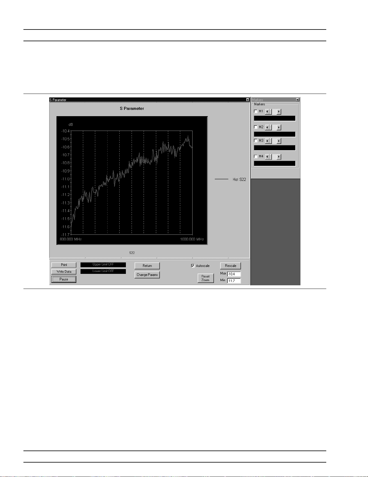
HOT S22 OPERATIONS, MEASUREMENT
Select Start Test and observe that the test screen
(Figure 5-9) appears.
Figure 5-9. Hot S22Test Screen
Button Panel Options:
q
Print: Prints a copy of the screen graphic to a
printer.
q
Write Data: Excel data is written to C:\Pro
gram Files\Pats\Datafiles - the file name will
have a time stamp. For example:
“S17-16-19-29.csv” was created on the 17th day
of the month at 4:19 PM and 49 seconds. CSV
files are comma separated text and can be
opened iin Windows Excel.
q
Pause/Go: Stops data transfer from VNA to
PC and places MS4623C in “Local” mode.
q
Upper Limit/Lower Limit: Limit values as
set using Tools menus (Chapter 4).
q
Return: Returns to the main PATS screen.
5-34 ME 7840A OMM
Page 96

OPERATIONS, MEASUREMENT HOT S22
Change Params: Returns to User Input
q
screen.
Autoscale Checkbox: Turns autoscale on or
q
off. Autoscale automatically scales the mea
surement results.
Reset/Zoom: Disabled for this test.
q
Max/Min: Type in maximum and minimum
q
display value. Use Rescale after changing val
ues.
Rescale: Rescales the measurement results.
q
Markers Screen Options (left):
M1: Turnsmarker on or off (checked or un
q
checked). If on: Slider moves marker between
data points, and window below displays marker
frequency and amplitude values amplitude
value at the marker.
M2: Same as above.
q
M3: Same as above.
q
M4: Same as above.
q
-
-
-
ME7840A OMM 5-35/5-36
Page 97

Chapter 6 Performance Verification Procedure
6-1 INTRODUCTION The following are the specific tests that should be used to verify the per
formance of the Power Amplifier Test System (PATS)
Source Output Level Accuracy Test
q
Return Loss Measurement Confidence Test
q
System Dynamic Range Test
q
Receiver Magnitude Display Linearity Test
q
6-2 CONVENTIONS In the tests in this chapter, instructions will direct use front panel hard
keys and softkeys. The hard keys and softkeys will appear in a different
typeface. For example:
Step 1. Press the Utility key and select:
DIAGNOSTICS
TROUBLESHOOTING
MORE
VERIFY ALC CALIBRATON
The Utility key is a front panel hard key and DIAGNOSTICS, TROUBLE
SHOOTING, MORE, and VERIFY ALS CALIBRATION are all softkeys.
6-3 TEST
EQUIPMENT
The following equipment is required to performthe verification proce
dures.
-
-
-
q
ANRITSU Model ML243XA Power Meter
q
ANRITSU Model MA247XA Power Sensor
q
ANRITSU Model 3653 or 3753LF N connector Calibration Kit
q
ANRITSU Model SC5237 6 dB Offset Termination
q
ANRITSU Model SC5270 20 dB Offset Termination
q
ANRITSU Model 11N50B Power Divider
q
ANRITSU Model 3670NN50-2 Cable
q
ANRITSU Model 34NN50A Adapter
q
ANRITSU 2100-2 GPIB cable
ME7840A OMM 6-1
Page 98

SOURCE OUTPUT ACCURACY PERFORMANCE VERIFICATION
6-4 SOURCE OUTPUT
ACCURACY
Setup:
This test verifies the source output accuracy of the MS462XC. The test
procedure uses the Power ALC Verification built-in function of the
MS462XC Basic Measurement software.
Step 1. Connect a GPIB cable between the power meter GPIB connec
tor and the MS462XC dedicated GPIB connector, as shown in
Figure 6-1.
Step 2. Turn on the MS462XC VNMS and allow it to warm-up at
least one hour.
00000001
WARNING
NOOPERATORSERVICE-
ABLEPARTSINSIDE.
REFERSERVICINGTO
QUALIFIEDPERSONNEL.
N274
PARALLELPRINTER
RS232
B
IEEE488.2
GPIB
Dedicated
GPIB
Madein UK
GPIB/ IEEE 488
WARNING
NOOPERATORSERVICE-
ABLEPARTSINSIDE.
A
CALIBRATOR
SerialPort
Ethernet
CAUTION
85-250VAC
DONOT OPERATE
47-440Hz
WITHUNGROUNDED
40VAMAX
POWERCORD.
OUTPUT1 OUTPUT2 INPUT1
DIGITAL
SEEMANUAL FOR VOLTAGERANGES ON BNC CONNECTORS
VGA
Ext
Analog
Output
INPUT2
12-24VDC
ANALOG
(1.3A)
SCSI-2
CAUTION
FORCONTINUED FIRE
PROTECTIONREPLACE
ONLYWITHSPECIFIED
TYPEAND RATEDFUSE.
CAUTION
DONOT OPERATE
WITHPOWERCORD
UNGROUNDED
ExtI/O
47-440Hz
85-264VAC
REPLACEFUSE ONLYWITH
SAMETYPE ANDRATING
LPTLine Printer
Ext
Trigger
-
Port2
Port1
Noise
In
Noise
+28V
Port2
Bias
Bias
BiasFuse
Ext
Port1
BiasFuse
Ext10 MHz
ExtAnalog
Source
In
In
Figure 6-1. ML2430A Series Power Meter GPIB connection to the MS462XX Vector Network Measurement System
Test Procedure
Step 1. Disconnect cables between MS462XC Port 1 and Port 1of
MS4782 Test Set and between Port 3 of MS462XC and Port 3
of MS4782 Test Set.
Step 2. Press Utility key and select:
DIAGNOSTICS
TROUBLESHOOTING
MORE
VERIFY ALC CALIBRATON
Step 3. Calibrate and zero the power sensor.
6-2 ME 7840A OMM
Page 99

PERFORMANCE VERIFICATION RETURN LOSS CONFIDENCE TEST
Step 4. Connect power sensor to MS462XC Port 1 and select START
VERIFICATION softkey.
NOTE
The worst case test result
will be displayed on the
screen when the instru
ment fails this test only.
Thefailedtestresultisalso
recorded in theService
Log.
Step 5. Verify that Source 1 passes this test.
Step 6. Press the SELECT SOURCE soft key to select 2
-
Step 7. Connect power sensor to MS462XC Port 3 and select START
VERIFICATION soft key.
CAUTION
The TROUBLESHOOTING function must be properly exited to restore
normal
Step 8. Verify that Source 2 passes this test.
Step 9. Select the menu soft key as follows to exit the TROUBLE-
SHOOTING mode:
RETURN
RETURN
FINISHED, RECOVER FROM TROUBLESHOOTINGT
Step 10. Reconnect cables between MS462XC Port 1 and Port 1of
MS4782 Test Set and between Port 3 of MS462XC and Port 3
of MS4782 Test Set.
6-5 RETURN LOSS
CONFIDENCE
TEST
Setup Turn on the MS462XC VNMS and MS4782X Test Set and allow them to
This test verifies the accuracy of return loss measurements.
warm up for 30 minutes.
Step 1. Press Default key then 0 key.
Step 2. Press Seq key and .select:
TTL I/O.
PARALLEL OUT SETUP
SET PARALLEL OUT PORT (0-255)
Step 3. Change the value from 0 to 8.
Step 4. Select:
ME7840A OMM 6-3
Page 100

RETURN LOSS CONFIDENCE TEST PERFORMANCE VERIFICATION
RETURN
RETURN
Step 5. Press Display key and select:
DISPLAY MODE
SINGLE CHANNEL
RETURN
Step 6. Press Ch 4 key and then Display key.
Step 7. Select:
GRAPH TYPE
LOG MAGNITUDE
Step 8. Press Ch 1 key and select LOG MAGNITUDE.
Test Procedure: Insert the Calibration Component Coefficients disk into the MS462XC
floppy disk drive.
Step 1. Press Cal key and select:
COMPONENT UTILTIES
INSTALL KIT INFO FROM FLOPPY DISK
RETURN
Step 2. Follow the prompts and select:
PERFORM CAL: 2 PORT
CAL METHOD: STANDARD
LINE TYPE: COAXIAL
SELECT CALIBRATION TYPE: REFLECTION ONLY–
PORT 1 ONLY
FREQUENCY RANGE OF CALIBRATION: 800 MHz TO
2400 MHz
SELECT CALIBRATION DATAPOINTS: NORMAL
DATA POINTS: 401 POINTS
PORT 1 CONNECTOR TYPE: N (F)
LOAD TYPE: BROADBAND LOAD
Step 3. Select START CAL soft key to begin calibration.
Step 4. Install calibration device per instruction on the display. Select
the appropriate soft key to measure the calibration device.
Step 5. When the “CALIBRATION SEQUENCE COMPLETED” mes
sage is displayed, press the Enter key to continue.
6-4 ME 7840A OMM
-
 Loading...