


Compact Washer |
Laveuse compactes |
Use and Care Guide |
Guide d’utilisation |
|
et d’entretien |
Para una versión de estas instrucciones en español, visite www.amana.com
Table of Contents |
Table des matières |
WASHER SAFETY....................................................................... |
2 |
INSTALLATION REQUIREMENTS............................................. |
3 |
PERMANENT INSTALLATION INSTRUCTIONS....................... |
6 |
PORTABLE INSTALLATION INSTRUCTIONS......................... |
10 |
CONTROL PANEL AND FEATURES........................................ |
13 |
USING YOUR WASHER............................................................ |
15 |
WASHER MAINTENANCE........................................................ |
18 |
TROUBLESHOOTING............................................................... |
20 |
WARRANTY.............................................................................. |
25 |
ASSISTANCE OR SERVICE................................... |
BACK COVER |
SÉCURITÉ DE LA LAVEUSE.................................................... |
|
26 |
EXIGENCES D’INSTALLATION................................................ |
|
27 |
INSTRUCTIONS D’INSTALLATION PERMANENTE............... |
31 |
|
INSTRUCTIONS POUR L’INSTALLATION PORTATIVE.......... |
35 |
|
TABLEAU DE COMMANDE ET CARACTÉRISTIQUES.......... |
39 |
|
UTILISATION DE LA LAVEUSE................................................ |
|
42 |
ENTRETIEN DE LA LAVEUSE.................................................. |
|
45 |
DÉPANNAGE............................................................................. |
|
48 |
GARANTIE................................................................................. |
|
54 |
ASSISTANCE OU SERVICE............... |
COUVERTURE ARRIÈRE |
|
Designed to use only HE High Efficiency detergents. Conçue pour utiliser un détergent haute efficacité seulement.
W10778944B W10778945B - SP

Washer Safety
2
Installation Requirements
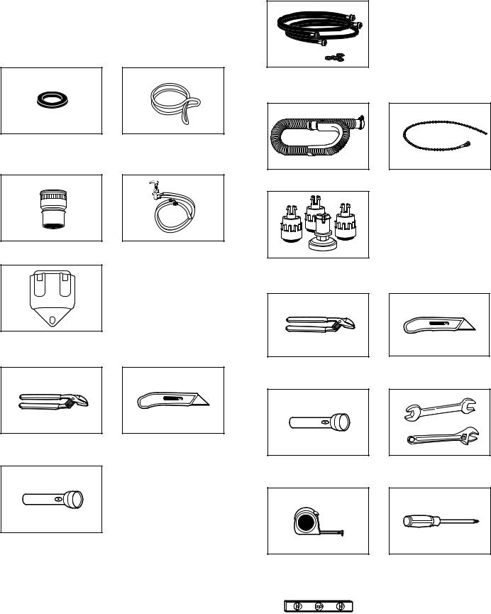
Tools and Parts
Gather the required tools and parts before starting installation. The parts supplied are in the washer basket.
Portable Installation
Parts supplied:
Permanent Installation
Parts needed (not provided with washer):
NOTE: Replace inlet hoses after 5 years of use to reduce the risk of hose failure. Record hose installation or replacement dates for future reference.
Inlet hoses with flat washers
Parts supplied:
Flat washers for faucet adapter and fill hoses
Faucet adapter
Silver, double-wire hose clamp (for bottom of drain hose)
Drain hose with clamp |
Cable tie |
Fill-and-drain hose
Leveling feet (4)
Tools needed for installation
Hose bracket
Tools needed for installation:
Pliers that open |
Utility knife |
to 19⁄16" (3.95 cm) |
|
Pliers that open |
Utility knife |
to 19⁄16" (3.95 cm) |
|
Flashlight (optional) |
Adjustable or open-end |
|
wrench 9⁄16" (14 mm) |
Flashlight (optional)
Measuring tape |
Phillips screwdriver |
|
|
|
|
Level
3
Alternate Parts
Your installation may require additional parts. For information on ordering, please refer to “Assistance or Service” on the back cover of this manual.
If You Have: |
You Will Need to Buy: |
|
|
Laundry tub or standpipe |
Sump pump system |
taller than 72" (183 cm) |
(if not already available) |
|
|
1" (2.5 cm) diameter |
2" (5 cm) diameter to |
standpipe |
1" (2.5 cm) diameter |
|
standpipe adapter, |
|
Part Number 3363920 |
|
|
Overhead sewer |
Standard 20 gal (76 L) |
|
39" (99 cm) tall drain tub or |
|
utility sink, sump pump, and |
|
connectors (available from |
|
local plumbing suppliers) |
|
|
Floor drain |
Siphon break, Part Number |
|
285320; additional drain |
|
hose, Part Number 3357090 |
|
and connector kit, Part |
|
Number 285442 |
|
|
Water faucets beyond reach |
2 longer water fill hoses: |
of fill hoses |
6 ft (1.8 m) |
|
|
|
Part Number 76314 |
|
10 ft (3.0 m) |
|
Part Number 350008 |
|
|
Drain hose too short |
Drain hose, Part Number |
|
388423 and hose kit, |
|
Part Number 285442 |
|
|
Drain hose that is too long |
Hose kit, |
|
Part Number 285442 |
|
|
Lint clogged drain |
Drain protector, |
|
Part Number 367031 |
|
|
Location Requirements
Selecting the proper location for your washer improves performance and minimizes noise and possible washer “walk.”
Your washer can be installed in a basement, laundry room, closet, or recessed area. See “Drain System.”
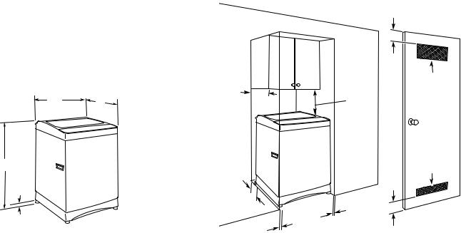
Washer Dimensions
21" |
23" |
|
(533 mm) |
||
(584 mm) |
||
|
37" (940 mm)
3/4"
(19 mm)*
*Minimum measurement with leveling feet installed.
IMPORTANT: Do not install or store the washer where it will be exposed to the weather.
Proper installation is your responsibility.
You will need:
■■ A water heater set to deliver 120°F (49°C) water to the washer.
■■ A grounded electrical outlet located within 5 ft (1.5 m) of where the power cord is attached to the back of the washer. See “Electrical Requirements.”
■■ Hot and cold water faucets located within 3½ ft (1.1 m) of the hot and cold water fill valves, and water pressure of 5–100 psi (34.5–690 kPa).
■■ A level floor with a maximum slope of ¾" (1.9 cm) under entire washer. Installing the washer on carpeting is not recommended.
■■ A sturdy floor to support the washer weight (washer, water, and load) of 225 lbs (102 kg).
Do not store or operate your washer in temperatures at or below 32°F (0°C). Some water can remain in the washer and can cause damage in low temperatures. See “Washer Care” for winterizing information.
Recessed area or closet installation
The dimensions shown are for the recommended spacing allowed, except the closet door ventilation openings. The dimensions shown for the closet door ventilation openings are the minimum required.
■■ Additional spacing should be considered for ease of installation and servicing.
■■ Additional clearances may be required for wall, door, and floor moldings.
■■ Additional spacing of 1" (2.5 cm) on all sides of the washer is recommended to reduce noise transfer.
■■ If a closet door is installed, the minimum air openings in the top and bottom of the door are required. Louvered doors with air openings in the top and bottom are acceptable.
■■ Companion appliance spacing should also be considered.
Washer Only
3" (76 mm)
14" max. |
48 in.2 |
(356 mm) |
(310 cm2) |
|
17" |
|
(432 mm) |
|
|
24 in.2 |
4" |
|
(155 cm2) |
(102 mm) |
|
|
|
1" |
|
1" |
(25 mm) |
3" |
|
||
|
(76 mm) |
|
(25 mm) |
|
|
|
|
|
Recessed area |
Closet door with vents |
|
4
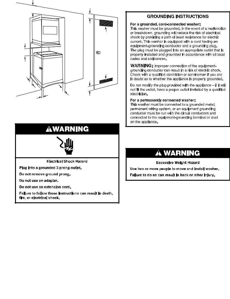
Stacked |
|
|
|
|
|
3" |
|
12" |
|
(76 mm) |
|
|
|
||
(305 mm) |
|
|
|
|
DRYER |
48 in.2 |
|
|
|
||
|
|
(310 cm2) |
|
12" |
|
|
|
(305 mm) |
|
|
|
|
WASHER |
24 in.2 |
|
3" |
|
(155 cm2) |
|
(76 mm) |
|
|
|
1" |
1" |
3" |
|
(25 mm) |
(76 mm) |
||
(25 mm) |
|||
|
|
Recessed area |
Closet door with vents |
Electrical Requirements
■■ A 120-volt, 60 Hz, AC-only, 15or 20-amp, fused electrical supply is required. A time-delay fuse or circuit breaker is recommended. It is recommended that a separate circuit serving only this appliance be provided.
■■ This washer is equipped with a power supply cord having a 3 prong grounding plug.
■■ To minimize possible shock hazard, the cord must be plugged into a mating, 3 prong, grounding-type outlet, grounded in accordance with local codes and ordinances. If a mating outlet is not available, it is the personal responsibility and obligation of the customer to have the properly grounded outlet installed by a qualified electrician.
■■ If codes permit and a separate ground wire is used, it is recommended that a qualified electrician determine that the ground path is adequate.
■■ Do not ground to a gas pipe.
■■ Check with a qualified electrician if you are not sure if the washer is properly grounded.
■■ Do not have a fuse in the neutral or ground circuit.
Remove Shipping Material
Before you install your washer, remove all shipping material.
To avoid damaging floor, use a large flat piece of cardboard from the washer carton. Place cardboard under entire back of the washer.
Firmly grasp the body of the washer and gently lay it on the corner posts.
Remove plastic foam packaging from underneath the washer. Stand the washer up.
Remove tape from washer lid. Open washer lid and remove foam shipping piece, parts bag, and hoses from washer basket. Close the lid.
5
Drain System
The washer can be installed using the standpipe drain system (floor or wall), the laundry tub drain system, or the floor drain system. Select the drain hose installation method you need. See “Tools and Parts.”
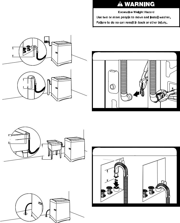
Standpipe drain system – wall or floor (views A & B)
The standpipe drain requires a minimum diameter standpipe
of 2" (50 mm). The minimum carry-away capacity (for permanent installations) can be no less than 17 gal (64.5 L) per minute. A 2" (50 mm) diameter to 1" (25 mm) diameter standpipe adapter kit is available. See “Tools and Parts.”
The top of the standpipe must be at least 39" (990 mm) high and no higher than 72" (183 cm) from the bottom of the washer.
4.5" (114 mm)
A
4.5"
(114 mm)
B
Laundry tub drain system (view C)
The laundry tub requires a minimum carry-away capacity of 17 gal (64.5 L) per minute (for permanent installations).
The top of the laundry tub must be at least 39" (990 mm) above the floor and no higher than 72" (183 cm) from the bottom of the washer.
4.5" (114 mm)
min.. 39"0
(990 mm)
C
Floor drain system (view D)
The floor drain system requires a siphon break that may be purchased separately. See “Tools and Parts.”
The siphon break must be a minimum of 28" (710 mm) from the bottom of the washer. Additional hoses might be needed.
The minimum carry-away capacity (for permanent installations) can be no less than 17 gal (64.5 L) per minute.
D
Permanent Installation
Instructions
■■ To avoid damage to the floor, set the washer onto cardboard before moving across floor.
■■ Move the washer to within approximately 3 ft (900 mm) of the final location.
Connect Drain Hose
1. Attach drain hose to drain port
If clamp is not already in place on elbow end of drain hose, slide it over end as shown. Squeeze clamp with pliers and slide black elbow end of drain hose onto black drain port and secure with clamp.
For a laundry tub or standpipe drain, go to Step 2.
For a floor drain, remove the preinstalled drain hose form as shown in Step 3. You may need additional parts with separate directions. See “Tools and Parts.”
Install Drain Hose
2. Place drain hose in standpipe
Drain hose form
4.5"  (114 mm)
Place hose into standpipe (shown in picture) or over side of laundry tub.
IMPORTANT: 4.5" (114 mm) of drain hose should be inside standpipe; do not force excess hose into standpipe or lay on bottom of laundry tub. Drain hose form must be used.
6
3. Remove drain hose form (floor drain installations only)
For floor drain installations, you will need to remove the drain hose form from the end of the drain hose. You may need additional parts with separate directions. See “Tools and Parts.”
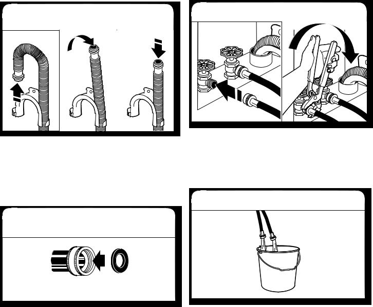
Connect Inlet Hoses
The washer must be connected to the water faucets using new inlet hoses (not provided). Do not use old hoses.
4. Insert new flat washers into inlet hoses
Coupling Washer
Insert new flat washers (not provided) into each end of the inlet hoses. Firmly seat the washers in the couplings.
5. Connect inlet hoses to water faucets
Check that the washer basket is empty.
Attach hose to hot water faucet. Screw on coupling by hand until it is seated on washer. Use pliers to tighten couplings an additional two-thirds turn. Repeat this step with second hose for cold water faucet.
IMPORTANT: Do not overtighten or use tape or sealants on valve when attaching to faucets or washer. Damage can result.
6. Clear water lines
Run water for a few seconds through hoses into a laundry tub, drainpipe, or bucket to avoid clogs. Water should run until clear.
Make note of which hose is connected to hot water to help in attaching hoses to washer correctly.
7

7. Connect inlet hoses to washer
Remove inlet cap and attach hot water hose to hot water (right) inlet valve. Screw coupling by hand until it is snug. Use pliers to tighten couplings an additional two-thirds turn. Repeat with cold water (left) inlet valve.
IMPORTANT: To reduce risk of hose failure, replace the hoses every 5 years. Record hose installation or replacement dates for future reference.
■■ Periodically inspect and replace hoses if bulges, kinks, cuts, wear, or leaks are found.
8. Check for leaks
Turn on water faucets to check for leaks. A small amount of water may enter washer. It will drain later.
■■ If you connect only one water hose, you must cap (supplied) off the remaining water inlet port.
Secure Drain Hose
9. Secure drain hose to laundry tub, standpipe, or wall
Laundry Tub |
Standpipe |
Wall |
4.5"4.5" |
4.5" |
4.5" |
(114 mm) |
||
(114 mm) |
|
(1143 mm) |
Secure drain hose to laundry tub leg, drain standpipe, or inlet hoses for wall standpipe with cable tie (provided).
■■ Do not force excess drain hose back into the rear of the washer.
■■ To avoid siphoning, do not seal or put more than 4½" (114 mm) of the drain hose into drainpipe or standpipe.
Install Leveling Feet – Optional (for permanent installation only)
IMPORTANT: Installation of the leveling feet is permanent. Once the leveling feet are installed into the base of the washer they cannot be removed.
10. Install leveling feet
Front |
Large |
black |
rubber |
foot |
Lay washer on its back. Push in to snap the large black rubber foot into the right front corner of the washer base. Repeat to install the remaining leveling feet on the other 3 corners.
8
 Loading...