


 Loading...
L-97 |
SERVICE MANUAL |
WHIRLPOOL & MAYTAG |
27” FRONT-LOAD WASHERS |
W11169652A |

FORWARD
This Whirlpool Service Manual, (Part No. W11169652A), provides the In-Home Service Professional with service information for the “WHIRLPOOL & MAYTAG 27” FRONT-LOAD WASHERS.”
The Wiring Diagram used in this Service Manual is typical and should be used for training purposes only. Always use the Wiring Diagram supplied with the product when servicing the washer.
For specific operating and installation information on the model being serviced, refer to the “Use and
Care Guide” or “Installation Instructions” provided with the washer.
GOALS AND OBJECTIVES
The goal of this Service Manual is to provide information that will enable the In-Home Service
Professional to properly diagnose malfunctions and repair the “WHIRLPOOL & MAYTAG FRONT-LOAD
WASHERS.”
The objectives of this Service Manual are to:
•Understand and follow proper safety precautions.
•Successfully troubleshoot and diagnose malfunctions.
•Successfully perform necessary repairs.
•Successfully return the washer to its proper operational status.
WHIRLPOOL CORPORATION assumes no responsibility for any repairs made on our
products by anyone other than authorized In-Home Service Professionals.
Copyright © 2019, Whirlpool Corporation, Benton Harbor, MI 49022
ii n Whirlpool & Maytag Front-Load Washers

TABLE OF CONTENTS
WHIRLPOOL&MAYTAG FRONT-LOAD WASHERS
SECTION1—GENERAL INFORMATION
WASHER SAFETY................................................................................................................................. |
1-2 |
WHIRLPOOL CONTROL PANEL&FEATURES(HMI IN DOOR MODELS) .............................................. |
1-3 |
WHIRLPOOL CONTROL PANEL&FEATURES(CONSOLE MODELS) ..................................................... |
1-4 |
MAYTAG CONTROL PANEL&FEATURES(CONSOLE MODELS) ............................................................ |
1-6 |
DISPENSERS-WHIRLPOOL WASHERS ONLY....................................................................................... |
1-9 |
DISPENSERS-MAYTAG WASHERS ONLY............................................................................................. |
1-9 |
MODEL & SERIAL NUMBER LOCATION............................................................................................. |
1-10 |
WIRING DIAGRAM LOCATION.......................................................................................................... |
1-10 |
MODEL AND SERIAL NUMBER NOMENCLATURE............................................................................. |
1-11 |
CLEANING THE DRAIN PUMP FILTER/DRAINING RESIDUAL WATER............................................... |
1-12 |
PRODUCT SPECIFICATIONS............................................................................................................... |
1-13 |
SECTION2—DIAGNOSTICS&TROUBLESHOOTING
WHIRLPOOL&MAYTAG DIAGNOSTICS(CONSOLE MODELS) |
............................................................2-2 |
WHIRLPOOL CONTROL PANEL......................................................................................................... |
2-2 |
MAYTAG CONTROL PANEL.............................................................................................................. |
2-3 |
ABBREVIATIONS............................................................................................................................. |
2-4 |
DIAGNOSTIC GUIDE........................................................................................................................ |
2-4 |
SERVICE DIAGNOSTIC MODE.......................................................................................................... |
2-4 |
ACTIVATING SERVICE DIAGNOSTIC MODE....................................................................................... |
2-4 |
SERVICE DIAGNOSTIC MENU.......................................................................................................... |
2-4 |
HUMAN-MACHINE INTERFACE (HMI) TEST...................................................................................... |
2-5 |
SOFTWARE VERSION DISPLAY......................................................................................................... |
2-5 |
LOAD TEST AND QUICK SERVICE CYCLE........................................................................................... |
2-6 |
LOAD TEST CHART.......................................................................................................................... |
2-6 |
QUICK SERVICE CYCLE CHART......................................................................................................... |
2-7 |
FAULT/ERROR CODES ..................................................................................................................... |
2-8 |
WHIRLPOOL DIAGNOSTICS(LCD IN DOOR MODELS)......................................................................... |
2-9 |
ABBREVIATIONS............................................................................................................................. |
2-9 |
DIAGNOSTIC GUIDE........................................................................................................................ |
2-9 |
SERVICE DIAGNOSTIC MODE.......................................................................................................... |
2-9 |
ACTIVATING SERVICE DIAGNOSTIC MODE....................................................................................... |
2-9 |
SERVICE DIAGNOSTIC MODE TESTS............................................................................................... |
2-10 |
COMPONENT ACTIVATION............................................................................................................ |
2-11 |
QUICK SERVICE CYCLE................................................................................................................... |
2-12 |
FAULT/ERROR CODES........................................................................................................................ |
2-13 |
TROUBLESHOOTING GUIDE.............................................................................................................. |
2-16 |
MANUALLY UNLOCKING THE DOOR................................................................................................. |
2-20 |
SECTION3—COMPONENT TESTING
COMPONENT TESTING: SAFETY INFORMATION................................................................................ |
3-2 |
WIRING DIAGRAM-WHIRLPOOL WASHER,LCD IN DOOR MODELS ................................................. |
3-3 |
WIRING DIAGRAM-WHIRLPOOL WASHER,CONSOLE MODELS ....................................................... |
3-4 |
WIRING DIAGRAM-MAYTAG WASHER,CONSOLE MODELS ............................................................. |
3-5 |
COMPONENT TESTING........................................................................................................................ |
3-6 |
TEST #1: ACU POWER CHECK.............................................................................................................. |
3-6 |
ACU BOARD/CONNECTORS & PINOUTS............................................................................................. |
3-7 |
TEST#2A:HUMAN-MACHINE INTERFACE(HMI)LCD IN DOOR MODELS .......................................... |
3-8 |
TEST#2B:HUMAN-MACHINE INTERFACE(HMI)CONSOLE MODELS ................................................. |
3-9 |
TEST#3:MOTOR CIRCUIT.................................................................................................................. |
3-10 |
TEST#4:DOOR LOCK SYSTEM........................................................................................................... |
3-11 |
Continued on next page . . .
Whirlpool & Maytag Front-Load Washers n iii

TABLE OF CONTENTS
WHIRLPOOL&MAYTAG FRONT-LOAD WASHERS
SECTION3—COMPONENT TESTING(CONTINUED)
TEST #5: DRUM LIGHT....................................................................................................................... |
3-12 |
TEST#6:WATER INLET VALVES.......................................................................................................... |
3-13 |
TEST #7: WATER LEVEL SENSOR........................................................................................................ |
3-14 |
TEST #8: DRAIN/RECIRCULATION PUMP.......................................................................................... |
3-15 |
TEST#9:WASH HEATING ELEMENT.................................................................................................. |
3-16 |
TEST#10:WASH TEMPERATURE SENSOR......................................................................................... |
3-17 |
TEST #11A: SINGLE DOSE DISPENSER............................................................................................... |
3-18 |
TEST#11B:OPTIMAL DISPENSER-DOSING PUMP............................................................................ |
3-19 |
TEST #12A: DRAWER BULK DISPENSER............................................................................................. |
3-20 |
TEST #12B: DRAWER BULK DISPENSER LEVEL SENSING................................................................... |
3-21 |
TEST#13:VENT FAN MOTOR............................................................................................................. |
3-22 |
TEST#14:VENT BAFFLE SOLENOID................................................................................................... |
3-23 |
TEST #15: DRY HEATING ELEMENT.................................................................................................... |
3-24 |
TEST#16:DRY TEMPERATURE SENSOR............................................................................................ |
3-25 |
TEST #17: DRY BLOWER MOTOR....................................................................................................... |
3-26 |
SECTION4—COMPONENT ACCESS
REMOVING THE TOP PANEL................................................................................................................ |
4-2 |
REMOVING THE REAR PANEL.............................................................................................................. |
4-3 |
REMOVING THE WATER LEVEL SWITCH.............................................................................................. |
4-4 |
REMOVING THE RFI FILTER................................................................................................................. |
4-5 |
REMOVING THE DRUM LIGHT............................................................................................................ |
4-6 |
REMOVING THE DVT FAN/VENT ASSEMBLY....................................................................................... |
4-7 |
REMOVING THE WATER INLET VALVES............................................................................................... |
4-8 |
REMOVING THE APPLIANCE CONTROL UNIT(ACU)........................................................................... |
4-9 |
REMOVING THE TOP REAR BRACKET............................................................................................... |
4-10 |
REMOVING THE WASH HEATER/THERMISTOR ASSEMBLY.............................................................. |
4-11 |
REMOVING THE DRYER HEATING CHANNEL ASSEMBLY.................................................................. |
4-12 |
REMOVING THE CONDENSER DUCT ASSEMBLY............................................................................... |
4-13 |
REMOVING THE DOOR ASSEMBLY.................................................................................................... |
4-14 |
REMOVING THE DOOR LOCK ASSEMBLY.......................................................................................... |
4-15 |
REMOVING THE FRONT CONSOLE.................................................................................................... |
4-16 |
REMOVING THE FRONT PANEL......................................................................................................... |
4-17 |
REMOVING THE SINGLE DOSE DISPENSER ASSEMBLY..................................................................... |
4-18 |
REMOVING THE DIRECT DRIVE MOTOR........................................................................................... |
4-19 |
REMOVING THE BULK DISPENSE ASSEMBLY.................................................................................... |
4-20 |
REMOVING THE DRAIN/RECIRCULATION PUMPS............................................................................ |
4-22 |
REMOVING THE TUB ASSEMBLY....................................................................................................... |
4-23 |
SECTION5—CONNECTIVITY
INTERNET CONNECTIVITY GUIDE....................................................................................................... |
5-2 |
INITIAL SETUP..................................................................................................................................... |
5-2 |
DOWNLOAD AND INSTALL WITH TOUCH SCREEN.............................................................................. |
5-2 |
DOWNLOAD AND INSTALL WITH NON-TOUCH SCREEN ..................................................................... |
5-2 |
TROUBLESHOOTING GUIDE................................................................................................................ |
5-3 |
PRODUCT SPECIFICATIONS & WARRANTY INFORMATION SOURCES (inside back cover)
iv n Whirlpool & Maytag Front-Load Washers

GENERAL INFORMATION
Section 1:
General Information
This section provides general safety, parts, and information for the “Whirlpool & Maytag Front-Load Washers.”
Washer Safety
Whirlpool Control Panel & Features (HMI in Door)
Whirlpool Control Panel & Features (Console)
Maytag Control Panel & Features (Console)
Dispensers – Whirlpool Washers
Dispensers – Maytag Washers
Wiring Diagram Location
Model & Serial Number Location
Model & Serial Number Nomenclature
Cleaning the Drain Pump/Draining Residual Water
Product Specifications
Whirlpool & Maytag Front-Load Washers n 1-1
GENERAL INFORMATION
Washer Safety
Your safety and the safety of others are very important.
many important safety messages in this manual and on your appliance. Always read and obey all safety
safety alert symbol.
alerts you to potential hazards that can kill or hurt you and others.
messages will follow the safety alert symbol and either the word “DANGER” or “WARNING.” mean:
 DANGER
  WARNING
You can be killed or seriously injured if you don't immediately follow instructions.
You can be killed or seriously injured if you don't follow instructions.
All safety messages will tell you what the potential hazard is, tell you how to reduce the chance of injury, and tell you what can happen if the instructions are not followed.
1-2 n Whirlpool & Maytag Front-Load Washers

GENERAL INFORMATION
Whirlpool Control Panel & Features (HMI in Door Model)
Not all features and cycles are available on all models.
NOTE: The control panel features a sensitive surface that responds to a light touch of your finger. To ensure your selections are registered, touch the control panel with your fingertip, not your fingernail. When selecting a setting or option, simply touch the appropriate button.
2 |
5 |
4:28 
3:15 
What to Wash How to Wash
REGULAR NORMAL
Temperature
WARM
1 3
1POWER BUTTON
Touch to power up the washer.
2HOME BUTTON
Touch this button and the LCDscreenwill showthehome screen,whereyoucan selectyourcycle,settings,and options..
3FAVORITES BUTTON
Stores and accesses your favorite cycles and a history of your recently run cycles.
4LCD SCREEN
Use this screen to select cycle, settings, options, etc.
5REMOTE ENABLE BUTTON
Download the Whirlpool™ app and follow the instructions to connect your washer to your home Wi-Fi network. You may also visit www.whirlpool.com/connect. In Canada, visit www.whirlpool.ca/connect. After connecting to WiFi, touch the REMOTE ENABLE button any time you want to use the app. Touching this button locks out the LCD screen and you will be prompted with a message about the washer waiting for input from the app. If you want to exit this mode, touch the REMOTE ENABLE button again.
6START/PAUSE BUTTON
Touch and hold to start, or touch to pause a cycle. When you start a cycle, the door will lock, the washer will sense the load size, and the wash cycle will begin.
7TOOLS BUTTON
The Tools button gives access to many other settings, utility cycles, preferences, and information (see next column). Touch the TOOLS button to access the Tools screen, which contains the following (you will need to scroll down with your finger to access all of the selections):
Spin Speed |
Auto Dry |
EXTRA FAST |
Dry |
|
|
|
|
7 |
6 |
4 |
|||
Load & Go™ Dispenser 1
Touch this icon to access Load & Go™ Status Dispenser 1 and choose between; Active, Disabled (1 Cycle), or Off (Permanently), and select detergent concentration of 2X, 3X, 4X, 5X, 6X, and 8X.
Load & Go™ Dispenser 2
Touch this icon to access Load & Go™ Status Dispenser 1 and choose between; Active, Disabled (1 Cycle), or Off (Permanently), choose between Softener or Detergent content, and select detergent concentration of 2X, 4X, 6X, and 8X.
Control Lock
Touch this icon to lock the controls. Swipe up to unlock.
Mute
Touch this icon to mute or unmute sounds.
Utility Cycles
Touch this icon to access the following utility cycles: Drain & Spin and the Clean Washer with affresh® cycle. Touch the utility cycle you wish to use and follow the screen prompts.
NOTE: To get a Rinse & Spin cycle, select Drain & Spin and the Extra Rinse option.
Preferences
Touch to access Times and Dates, Sound Volume, Display
Settings, and Regional. Follow the screen prompts.
WiFi
Touch to access Connect to Network, SAID (Smart Appliance
ID) Codes, Mac Address, and WiFi. Follow the screen prompts.
Info
Touch to access Service & Support, Store Demo Mode, Restore Factory, WiFi Terms and Conditions, and Software Terms and Conditions. Follow the screen prompts.
NOTE: All changes to settings will remain in effect until settings are changed again.
Whirlpool & Maytag Front-Load Washers n 1-3
GENERAL INFORMATION
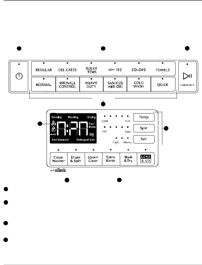
Whirlpool Control Panel & Features (Console Models)
NOTES:
■Not all features and cycles are on all models.
■If your model has a touch interface, the control panel features a sensitive surface that responds to a light touch of your nger. To ensure your selections are registered, touch the control panel with your ngertip, not your ngernail. When selecting a setting or option, simply touch its name.
■If your model has physical buttons, make sure to press the button rmly.
■At cycle completion, your setting and option choices will be remembered for the next cycle. However, if power to the washer is lost, the settings and options will go back to the factory defaults.
1 |
2 |
3 |
||||||||||||
|
|
|
|
|
|
|
|
|
|
|
|
|
|
|
|
|
|
|
|
|
|
|
|
||||||
|
|
|
|
|
|
|
WHAT |
to wash |
|
|
|
|
|
|
|
|
|
|
|
|
|
|
|
|
|
|
|
|
|
|
|
|
|
|
|
|
|
|
|
|
|
|
|
|
|
|
|
|
|
|
|
|
|
|
|
|
|
|
|
|
|
|
|
|
|
|
|
|
|
|
|
|
|
|
|
|
|
|
|
|
|
|
|
|
|
|
|
|
|
|
|
|
|
|
|
|
|
|
|
|
|
|
|
|
|
|
|
|
|
|
|
|
|
|
|
|
|
|
|
HOW to wash
2
4
5
|
|
|
|
|
|
|
|
|
|
|
|
|
|
|
|
|
|
|
|
|
|
|
|
|
|
|
|
|
|
|
|
|
|
|
|
|
|
|
|
|
KROG VHF IRU KROG VHF IRU |
|
KROG VHF IRU KROG VHF IRU |
|
|||
|
|
|
|
|
|
|
|
|
|
|
|||||
|
|
|
|
|
|
|
|
|
&\FOH 6LJQDO |
&RQWURO /RFN |
|
)DQ)UHVK |
3UH6RDN |
|
|
|
|
|
|
|
|
|
|
|
|
|
|
|
|
|
|
|
|
|
|
|
|
|
|
|
|
|
|
|
|
|
|
|
6 |
|
|
|
|
|
|
|
7 |
|
|
|
|||
Cycles and settings vary by model.
1POWER
Select to turn the washer on and off. Select to stop/cancel a cycle at any time.
2WHAT TO WASH/HOW TO WASH
First determine what items are in the load that you are trying to wash. Use that to guide your “What to Wash” selection. Then determine how you want the washer to wash them and make the appropriate “How to Wash” selection.
See “Cycle Guide” for cycle details. If you do not make a
3START/PAUSE“How to Wash” selection, the washer will automaticlly select Touchtherecommendedand hold for or3secondslast-useduntil“HowthetolightWash”abovecycleStart/.
Pause comes on to start a cycle, or touch once while a cycle
3 START/PAUSE
is in process to pause it.
Touch and hold for 3 seconds until the light above Start/
4 CYCLEPause comesSTATUSon toDISPLAYstart a cycle, or touch once while a cycle Theisin CycleprocessStatusto pauDiseplayit. shows the progress of a cycle.
At each stage of the process, you may notice sounds
4 CYCLE STATUS DISPLAY
or pauses that are different from traditional washers. The Cycle Status Display shows the progress of a cycle.
At each stage of the process, you may notice sounds or pauses that are different from traditional washers.
Estimated Time Remaining
The Estimated Time Remaining shows the time required for the cycle to complete. Factors such as load size, modi‰ers, options selected, and water pressure may affect the time shown in the display. Tightly packed loads, unbalanced loads, or excessive suds may cause the washer to lengthen the cycle time as well.
Sensing
When Start/Pause is touched the washer will chime, indicating it is starting. The drum will make a partial turn. The door will click when it locks.
Once the door has locked, the washer will begin spinning to sense the load size. This sensing process will continue throughout the cycle.
After the load size is sensed, the estimated time based
on load size will be displayed and water will be added. You may hear water Œowing through the dispenser, adding detergent to the load. The actual cycle time may be lengthened; however, the display will continue to show the estimated time.
1-4 n Whirlpool & Maytag Front-Load Washers

GENERAL INFORMATION
Washing
During the wash cycle, this will display to let you know the cycle is in progress.
Drying (on some models)
During a drying cycle, this will display to let you know the drying cycle is in progress.
Cool Down (on some models)
At the end of a drying cycle, your load will go through a cool-down period.
PreSoak
This symbol will be displayed to let you know
a presoak is in progress.
Detergent Low (on some models)
When detergent in the bulk dispenser is running low, the display will show the detergent level (Low).
Add Garment
When “Add Garment” is displayed, you may pause the washer, open the door, and add items. Touch and hold START/PAUSE to start the washer again.
Door Locked
The Door Locked symbol will display to indicate that the door is locked and cannot
be opened without „rst pausing or canceling the cycle.
Control Lock
When the Contol Lock symbol is displayed,  the buttons are disabled. Touch and hold EXTRA RINSE for 3 seconds to enable the buttons.
FanFresh® (on some models)
This symbol will be displayed when the FanFresh®
option is activated. The fan will turn on and the load will tumble periodically for up to 12 hours.
End
Once the cycle is complete, “End” will display. Remove the load promptly for best results.
5CYCLE MODIFIERS
When you select a cycle, its default settings will light up. Touch to adjust cycle modi„ers on the washer before touching START/PAUSE. Additional wash modi„ers or options selected after touching Start/Pause may not activate.
Once a wash setting is selected, it is saved for the cycle selected. To return to factory default cycle settings, unplug washer for 30 seconds; then plug back in. See “Cycle Guide” for default cycle settings.
NOTE: Some modi„ers may increase or decrease the estimated time remaining.
Temp
The recommended wash temperature is preset for each cycle. Some preset temperatures can be changed. You may select a different wash temperature based on the level of soil and type of fabric being washed. For best results, use the warmest wash water safe for your fabric, following the garment label instructions. All wash temperatures feature a cold rinse.
Spin
The recommended spin speed is preset for each cycle. Some preset speeds can be changed.
■Faster spin speeds mean shorter dry times, but may increase wrinkling in your load.
■Slower spin speeds reduce wrinkling, but will leave your load more damp.
Soil
The recommended soil level is preset for each cycle. Some preset soil levels can be changed. For heavily soiled and sturdy fabrics, select the Heavy Soil Level setting. For lightly soiled and delicate fabrics, select the Light Soil Level setting. Lower soil level settings will help reduce tangling and wrinkling.
6 UTILITY CYCLES
Clean Washer
Use this every 30 washes to keep the inside of your washer fresh and clean. This cycle uses a higher water level. Use with affresh® Washer Cleaner tablets or liquid chlorine bleach to thoroughly clean the inside of your washer. When using this cycle, the drum should be empty. This cycle should not be interrupted. See the “Washer Care” section.
Drain & Spin
This cycle removes excess water from the load or special-care items washed by hand. Use this cycle after a power failure. For some fabrics, you may choose to set a slower spin speed. On some models: Touch and hold DRAIN & SPIN for 3 seconds to set a Dry Only cycle.
7CYCLE OPTIONS
You may add or remove options for each cycle. Not all options can be used with all cycles, and some are preset to work with certain cycles. Options vary by model.
Steam Clean (on some models)
The Steam Clean option adds additional soak and wash time to many cycles to help remove tough stains, as well as a steam boost for added cleaning power. An integrated heater helps to maintain optimal wash temperatures. See “Cycle Guide” for cycles that allow the Steam Clean option.
You can also touch and hold STEAM CLEAN for 3 seconds to turn cycle signals on or off.
Extra Rinse
Activate this option to add an extra rinse to most cycles.
You can also touch and hold EXTRA RINSE
for 3 seconds to disable/enable the Control Lock.
Wash&Dry(onsomemodels)
Touchtoaddaadryinggcycletotoyourloadafterthewash cyclehasfinished”nished..TheWash&&Dryoptionisdesigned towashanddry2small-4 lightlyloadssoiledovernightsynthetic. Cyclegarments,ti athleticwill varyuniforms,based onorloadworkoutcompositionwear. This. Foroptionoptimalhasdryan extraperformance-high-speedandspincyclefollowedtime, loadbyintermittenttumblingthe drum no more andthanfanoneactivation-quarter fullto.circulateThe cycleairwillthroughautomaticathe clothesly . terminate after a maximum 12-hour cycle time.
You can also touch and hold WASH & DRY for 3 seconds to activate/deactivate the FanFresh® option. Use the FanFresh® option if you will be unable to remove the load promptly. The washer
will automatically activate the fan after the cycle ends and tumble the load periodically for up to 12 hours.
IMPORTANT:
■Do not use dryer sheets.
■Do not dry comforters or large blankets.
Load & Go™ (on some models)
Touch to select this option If you want to automatically add HE detergent to the wash load at the proper time.
IMPORTANT: When using the dispenser cartridge with concentrated liquid detergent, be sure to change the detergent concentration settings in the control if the detergent used is different than factory preset of
2x concentration. Change the detergent concentration setting by touching and holding TEMP and SOIL for
3 seconds.
You can also touch and hold LOAD & GO™ for 3 seconds to set a presoak.
PreSoak (on some models)
Touch to add a presoak time of your choice to a wash cycle.
Whirlpool & Maytag Front-Load Washers n 1-5

GENERAL INFORMATION
Maytag Control Panel & Features (Console Models)
Not all features and cycles are available on all models.
NOTES:
The control panel features a sensitive surface that responds to a light touch of your nger. To ensure your selections are registered, touch the control panel with your ngertip, not your ngernail. When selecting a setting or option, simply touch its name.
At cycle completion, your setting and option choices will be remembered for your next use of that cycle. However, if power is lost to the washer, the settings and options will go back to the factory defaults.
2 |
4 |
5 |
1 |
|
|
||
|
|
A |
|
|
|
D |
|
|
|
F |
|
B |
E |
|
|
I |
|
|
|
|
6 |
6 |
3 |
2 |
4 |
5 |
1 |
|
|
A |
|
|
|
D |
|
|
|
F |
|
C |
E |
B |
|
I |
|
|
|
|
6 |
6 |
3 |
2 |
4 |
5 |
1 |
|
|
A |
|
|
|
D |
|
|
|
H |
|
C |
G |
B |
|
I |
|
|
|
|
6 |
6 |
3 |
1-6 n Whirlpool & Maytag Front-Load Washers
GENERAL INFORMATION
Maytag Control Panel & Features (continued)
1POWER
Touch to turn the washer on and off. Touch to stop/cancel a cycle at any time.
NOTE: Turning the Wash Cycle knob will also turn the washer on.
2WASH CYCLE KNOB
Turn the knob to select a cycle for your laundry load. Press the Wash Cycle knob to enable the Extra Power option.
NOTE: The Clean Washer with affresh® LED will •ash when the washer has run 30 wash cycles as a reminder to run the Clean Washer with affresh® cycle.
See “Cycle Guide” for detailed descriptions of cycles.
NOTE: For best results when using the Overnight Wash & Dry cycle, use for loads weighing 2 lbs or less, such as a soccer uniform or a running tank and shorts. Allow the cycle to run the full duration of 12 hours.
EXTRA POWER
Extra Power option can be used for increased cleaning power. Press the Wash Cycle Knob to activate the Extra Power option, which runs a cold pre-wash cycle before the main cycle. When Extra Power is activated, the Cycle Control Knob will illuminate and the estimated time remaining on the display will increase. On single load dispenser models, add an extra dose of detergent to the
Bleach/Detergent for Extra Power compartment when using Extra Power, for best results.
3START
Touch and hold for 3 seconds until the light above START comes on to start a cycle or touch once while a cycle is in process to pause it. If you want to add a garment, you can touch START when the “Add Garment” LED is on.
4LED DISPLAY AND SETTINGS
When you select a cycle, its default settings will light up and the Estimated Time Remaining will be displayed. Factors such as load size, wash temperature, and water pressure may affect the time shown in the display. Tightly packing, unbalanced loads, or excessive suds may cause the washer to lengthen the cycle time as well.
Touch the desired setting on the display to adjust. See
“Cycle Guide” for available settings on each cycle. Not all
Temp
settings are available with all cycles.
The recommended wash temperature is preset for each
cycleTemp. You may also select a wash temperature based onThethrecommendedtypeof fabricwashand soilstemperaturebeing washedis preset.Forforbeachst results,cycle.Youusemaythe alsowarmsestlectwashwashwatertempsaferaturefor yourbased fabric,onthe followingtypeof fabricthe garmentandsoilslabelbeinginstructionswashed. For.Allbestwash tremperaturessults,use thefeatuwarmesta coldwashrinsewater. safe for your
fabric, following the garment label instructions. All wash
Spin
temperatures feature a cold rinse.
This washer automatically selects the spin speed basedSpin on the cycle selected. Some preset speeds canThisbewaschangederautomatically. selects the spin speed
based on the cycle selected. Some preset speeds
Faster spin speeds mean shorter dry times but may can be changed.
increase wrinkling in your load.
Faster spin speeds mean shorter dry times but maySlower spin speeds reduce wrinkling but will leave
increase wrinkling in your load. your load more damp.
Slower spin speeds reduce wrinkling but will leave
Soil
your load more damp.
Soil Level (wash time) is preset for each wash cycle. WhenSoil you change the soil setting, the cycle time will increaseSoilLevelor(washdecreasetim )inisthepresetEs imatedfor achCyclewashTimecycle. displayWhenyou. change the soil setting, the cycle time will increase or decrease in the Estimated Cycle Time
For most loads, use the soil level that is preset with the cycle you have chosen. For heavily soiled and sturdy fabrics, use the Soil Level setting to select a higher soil level. For lightly soiled and delicate fabrics, use the Soil Level setting to select a lower soil level. Lower soil level settings will help reduce tangling and wrinkling.
5CYCLE STATUS LIGHTS
NOTE: Not all Cycle Status Lights are available on all models.
The Cycle Status Lights show the progress of a cycle. At each stage of the process, you may notice sounds or pauses that are different from traditional washers.
Sensing
Sensing
When START is touched and held, the washer will ˜rst WhenperformSTARTa selfis-testtouchedon theanddoorheld,lockthem chwashernismwillandfirstthe performs nsing lighta selfwill-testcomeandonthe. Yousensingw ll hearlightwilla click,comethe drumon. will Themakedruma partialwillturn,makeandpartialthe doorturnwillandclickthenagainstopasforit unlocksa few secondsbrie•y. The. Then,doorawiclickclickwillonebemoreheardtimeas thewhendoorit locksagain. .
Once the door has locked the second time, the washer will begin spinning to sense the load size. This sensing process will continue throughout the cycle. You may also hear water •owing through the dispenser, adding detergent to the load.
After the load size is sensed, the estimated time based on load size will be displayed. The actual cycle time may be lengthened; however, the display will continue to show the estimated time.
The sensing light will blink once a second at various times during the cycle, such as when the washer is reducing extra suds.
Washing
During the wash cycle, this will display to let you know the cycle is in progress.
Add Garment
When “Add Garment” is lit, you may pause the washer, open the door, and add items. Touch and hold START to start the washer again.
Detergent Low
When detergent in the dispenser is running low, the display will show the detergent level (Low).
6 OPTIONS
Touch to activate additional wash options or additional features on the washer. Not all options are available on all models.
ADelay Start
Touch this option to delay the start of the wash cycle by up to 12 hours.
Options - continued on next page . . .
Whirlpool & Maytag Front-Load Washers n 1-7

GENERAL INFORMATION
Maytag Control Panel & Features (continued)
BFresh Hold®/Fresh SpinTM
The Fresh Hold®/Fresh SpinTM option will periodically tumble the load after the end of the cycle for up to 24 hours while the integrated fan circulates air through the washer to reduce humidity. Fresh Spin™ also periodically tumbles the load after the end of the cycle but does not use an integrated fan. To turn on the Fresh Hold®/Fresh Spin™ option, touch FRESH HOLD. If, however, the Fresh Hold®/Fresh Spin™ option is turned on, it will stay on for all future cycles until turned back off – the washer remembers the last on/off status set. To turn off the Fresh Hold®/Fresh Spin™ option, touch FRESH HOLD.
To turn off the Fresh Hold®/Fresh Spin™ option when it is running, touch POWER.
NOTE: The door will lock while the Fresh Hold®/Fresh Spin™ option is active. To cancel the option and unlock the door, touch POWER.
CSteam
The Steam option adds additional soak and wash time to many cycles to help remove tough stains as well as a steam boost for added cleaning power. An integrated heater helps to maintain optimal wash temperatures.
DExtra Rinse
Activate this option to add an extra rinse to most cycles.
ECycle Signal
Touch and hold CYCLE SIGNAL for about 3 seconds the display will count down you will see “3,” then “2,” then “1.” The display will start displaying the sound levels you will see “1,” then “2,” then “3,” then “OFF.” When the CYCLE SIGNAL is released the last value shown will be the current selection.
FControl Lock
Touch and hold for 3 seconds to lock the controls to avoid unwanted changes or operation. Touch and hold 3 seconds again to unlock. For each second CONTROL LOCK is held down, the display will count down 1 second; you will see “3,” then “2,” then “1.” You may still touch START to pause the cycle or touch POWER to turn off the washer.
GWiFii Connect
DownloadtheMaytag™Maytag®appandfollowowtheinstructionsto ctoconnectyouryourwasher/dryertotoyouryourhomeWiFi-Finetwork. You.ou mayalso visititwww.maytag. .com/connect. ..InInCanada,visit www..maytag..ca..
HRemote Enable
Touchthisbuttonon totobebeabletotouseusethetheMaytag®® appapptoto controlremotelythecontrolwasherthe. Presswasher,t is buttonif RemoteeachEnabletime afteris desiredPower.
OnPressandthiswhenbuttonhe dooreachistimeopenedafterandPowerclosedOn. and when the I Extradoor isPopenedwer and closed.
I |
Extra Power |
|
|
The Extra Power option boosts stain –ghting performance |
|
|
on any w sh cycle with a dual temperature wash, c |
mbi ing |
|
The ExtraPower option boosts stain fighting performance |
|
|
cold and hot temperature during different phases of the |
|
|
on any wash cycle with a dual temperature wash, |
|
|
wash time. To use this function press the knob to activate |
|
|
combining cold and hot temperature during different |
|
|
the Extra Power option. For single dose dispe se |
and an |
phases of the wash time. To use this function press the additionalknob to activate1/2 thethemanufacturer’sExtra Powerecommendedoption. For singleamountdose intodispenserthe spenseradd anmarkedadditionalfor Extra1/2 thePowermanufacturer’s. For the Optimal Dispenserrecommendedit will amountut maticallyinto thedispensedispenserthe detergentmarked forat the opExtraimalPowertime. For Optimal Dispenser it will automatically dispense the detergent at the optimal time.
Remote Enable
Touch this button to be able to use the Maytag® app to remotely control the washer, if Remote Enable is desired. Press this button each time after Power On and when the door is opened and closed.
Extra Power
The Extra Power option boosts stain fighting performance on any wash cycle with a dual temperature wash, combining cold and hot temperature during different phases of the wash time. To use this function press the knob to activate the Extra Power option. For single dose dispensers add an additional 1/2 the manufacturer’s recommended amount into the dispenser marked for Extra Power. For Optimal Dispenser it will automatically dispense the detergent at the optimal time.
1-8 n Whirlpool & Maytag Front-Load Washers

GENERAL INFORMATION
Dispensers – Whirlpool Washers Only
Load & Go™ Bulk Dispenser (Varies by model) |
Single-load dispenser drawer |
The Load & Go™ dispenser gives you the convenience of not having to add HE detergent and fabric softener to the wash load every time. It also determines the best time and amount to add the detergent to the load.
A |
B |
A2-Liter Bulk Liquid High Efficiency (HE) detergent dispenser
This bulk dispenser holds up to 67.6 oz (2 L) of liquid HE detergent.
B1-Liter Bulk Liquid High Efficiency (HE) detergent/fabric softener dispenser
The single-load dispenser drawer gives you the convenience of adding HE detergent, liquid chlorine bleach, and liquid fabric softener to the wash load at the proper time.
E
D
C
CHigh Efficiency (HE) detergent compartment
This compartment holds liquid or powdered HE detergent for your main wash cycle, and automatically dispenses detergent in the cycle.
DLiquid fabric softener compartment
This bulk dispenser holds up to 33.8 oz (1 L) of liquid HE detergent or liquid fabric softener.
Each dispenser holds enough detergent or fabric softener for many loads of laundry. Each adds the appropriate quantity to the wash load at the proper time.
IMPORTANT: Do not use chlorine bleach or powdered detergent in the bulk dispenser. Powdered detergent and bleach must be added to the single load dispenser.
This compartment holds liquid fabric softener. It automatically dispenses liquid fabric softener at the optimum time in the cycle.
ELiquid chlorine bleach compartment
This compartment automatically dilutes and dispenses liquid chlorine bleach at the optimum time during the first rinse after the wash cycle. It cannot dilute powdered bleach.
Dispensers – Maytag Washers Only
Optimal Dispense Drawer (on some models)
The Optimal Dispense drawer gives you the convenience of automatically adding HE detergent, liquid chlorine bleach, and liquid fabric softener to the wash load at the proper time.
C
B
A
AOptimal Dispense Liquid High Efficiency “HE” detergent compartment
This compartment holds up to 14.3 oz (424 ml) of liquid HE detergent allowing you to avoid having to refill detergent for each load. Also, this will use just the right amount of detergent required for a particular load/cycle.
BLiquid fabric softener compartment
Automatically dilutes and dispenses liquid fabric softener at the optimum time in the cycle.
Use only liquid fabric softener in this dispenser.
Single Load Dispenser Drawer (on some models)
The dispenser drawer gives you the convenience of adding HE detergent, liquid chlorine bleach, and liquid fabric softener to the wash load at the proper time.
C |
B |
D |
CLiquid chlorine bleach compartment
Automatically dilutes and dispenses liquid chlorine bleach at the optimum time during the first rinse after the wash cycle. This compartment cannot dilute powdered bleach. On single load dispenser models, use this compartment to add an extra dose of detergent when using the Extra Power option.
DLiquid High Efficiency “HE” detergent compartment
This compartment holds liquid or powdered HE detergent for your main wash cycle.
Whirlpool & Maytag Front-Load Washers n 1-9

GENERAL INFORMATION
Model & Serial Number Location
Model & Serial Number
Label Location
Figure 1 - Model / Serial Number
Wiring Diagram Location
Wiring Diagram located under Top Panel taped to rear top bracket
ACU
Figure 2 - Wiring Diagram Location
1-10 n Whirlpool & Maytag Front-Load Washers

GENERAL INFORMATION
Model & Serial Number Nomenclature
MODEL NUMBER |
W |
F |
W |
9620 |
H |
C |
0 |
INTERNATIONAL SALES OR
MARKETING CHANNEL
BRAND
W = Whirlpool; M = Maytag
ACCESS
F = Front Load; T = Top Load
PRODUCT
W = Washer; C = All-In-One
FEATURE SET
Higher number represents higher feature set
YEAR OF INTRODUCTION
H = 2018
COLOR CODE
W = White; C = Chrome Shadow; BK = Black
ENGINEERING CHANGE
0 = Basic Release; 1 = First Revision
SERIAL NUMBER |
|
C |
8 25 |
10000 |
|
||||
|
|
|
|
|
PRODUCTION SITE
C = CLYDE, OH
YEAR OF PRODUCTION 8 = 2018; 9 = 2019
WEEK OF PRODUCTION
PRODUCT SEQUENCE NUMBER
Whirlpool & Maytag Front-Load Washers n 1-11

GENERAL INFORMATION
Cleaning the Drain Pump Filter/Draining Residual Water
NOTE: The following instructions only apply to the Whirlpool
front-load washers.
1.Open the dispenser drawer by pulling on the handle at the base of the washer. This will reveal the drain pump filter. Remove the drawer by releasing the tab on each side. See Figure 1.
Drain pump |
lter |
With your nger, push down on tab on right side of drawer, and up on tab on left side of drawer.
Left side |
Right side |
Figure 1
2.Place a broad, flat container beneath the drain pump filter to collect the drain water. Release the black hose from the hose clip, remove the plug, and drain the hose into the container (see Figure 2). Empty the container. Repeat this procedure if necessary until all the water has drained. Make sure that the black hose is completely dry, replace the plug, and secure the hose in the clip.
NOTE: If water does not drain well, push in hose slightly to remove any possible kinks.
Hose clip
Black hose
Figure 2
3.Lay a cotton cloth beneath the drain pump filter to ab any water still in it. Then remove the drain pump filter by turning it counterclockwise. See Figure 3.
4.Remove large clumps of lint by hand from the filter and place lint in a suitable waste container. Remove remaining residue from the filter by rinsing with water (see Figure 4).
Figure 4
5.Reinsert the drain pump filter by turning it clockwise. Make sure to turn it in as far as it will go, with the filter handle remaining as close as possible to the vertical position. See Figure 5.
Figure 5
6.Replace and close the dispenser drawer. Make sure to insert both rails simultaneously when replacing the drawer. You will hear a clicking sound that indicates the rails have engaged (see Figure 6). To ensure proper
placement of the drawer, pull out fully. The drawer should be fully engaged and the rails locked in place. Make sure the drain hose is secured in the hose clip and tucked underneath the cutout.
Figure 6
Figure 3
1-12 n Whirlpool & Maytag Front-Load Washers

GENERAL INFORMATION
Product Specifications
ELECTRICAL |
|
|
|
|
|
Voltage : |
|
120 VAC |
|
|
|
Hertz : |
|
60 Hz |
|
|
|
Amps : |
|
15-20 Amps Service |
|
|
|
PRIMARY FEATURES* |
|
|
|
|
|
Capacity : |
|
4.5, 4.8, 5.0 cu. ft. (Maytag) |
|
|
4.3, 4.5, 5.0 cu. ft. (Whirlpool) |
|
|
|
Control Panel : |
|
(Whirlpool) Front Console / Capacitive Touch / Electronic |
|
|
(Whirlpool) Display In Door / LCD Screen / Touch Screen |
|
|
(Maytag) Front Console/ Indicator Lights / Cycle Select Knob |
|
|
|
Drum Material : |
|
Stainless Steel |
|
|
|
Door Style : |
|
Left Door Swing, Window |
|
|
|
Motor Drive Type : |
|
Direct Drive |
|
|
|
Maximum Spin Speed : |
|
1160 RPM |
|
|
|
Automated Dispenser : |
|
Load & Go™ (Varies by model) |
|
|
|
Dispense System : |
|
Detergent, Fabric Softener, Bleach |
|
|
|
Fan Type : |
|
Fan Fresh® |
|
|
|
Automatic Load Size Sensing : |
|
Yes |
|
|
|
Out of Balance Sensing : |
|
Yes |
|
|
|
Recirculation Pump : |
|
Yes |
|
|
|
Advanced Vibration Control : |
|
Yes |
|
|
|
Sanitize : |
|
Yes |
|
|
|
Internal Heater : |
|
Select Models |
|
|
|
Steam Option : |
|
Select Models |
|
|
|
Interior Light : |
|
Select Models |
|
|
|
Closet Depth : |
|
Select Models |
|
|
|
Smart Appliance/Remote Control : |
|
Select Models |
|
|
|
INSTALLATION CONSIDERATIONS |
|
|
|
|
|
Pedestal Options : |
|
Yes |
|
|
|
Stackable : |
|
Yes |
|
|
|
OPTIONS* |
|
|
Control Lock : |
|
Locks the controls of the dryer |
|
|
|
Cycle Signal : |
|
Sound when cycle is complete |
|
|
|
Wash and Dry Option : |
|
Select Models |
|
|
|
DIMENSIONS |
|
|
|
|
|
Height : |
|
38 5/8” (98.4 cm) |
|
|
|
Width : |
|
27” (68.58 cm) |
|
|
|
Standard Depth : |
|
33 1/4” (84.46 cm) |
|
|
|
Closet Depth (Slim) : |
|
31 1/2” (80 cm) |
|
|
|
Gross Weight : |
|
Varies by model |
|
|
|
*Features and Options vary by brand and model. |
|
|
Whirlpool & Maytag Front-Load Washers n 1-13

GENERAL INFORMATION
Notes
1-14 n Whirlpool & Maytag Front-Load Washers

DIAGNOSTICS & TROUBLESHOOTING
Section 2:
Diagnostics &
Troubleshooting
This section provides diagnostic, fault codes, and troubleshooting information for the “Whirlpool & Maytag Front-Load Washers.”
Control Panel
Abbreviations
Diagnostic Guide
Service Diagnostic Mode
Fault/Error Codes
Troubleshooting Guide
Manually Unlocking the Door
Whirlpool & Maytag Front-Load Washers n 2-1
Washers Load-Front Maytag & Whirlpool n 2-2
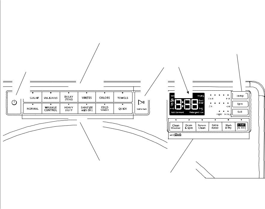
WHIRLPOOL CONTROL PANEL (features and appearances may vary between models)
(buttons to use when entering Service Diagnostic Mode & Tests)
Pressing each “WHAT to wash” button turns off each corresponding indicator.
Power button: press once to exit service diagnostic mode and return to standby mode.
WHAT to wash
Start/Pause button: press once to turn off indicator, the seven-segment display, and status indicators.
Press each modifier button once to turn off its respective display segment.
HOW to wash
hold 3 sec for |
hold 3 sec for |
hold 3 sec for |
hold 3 sec for |
Cycle Signal |
Control Lock |
FanFresh |
PreSoak |
Pressing each “HOW to wash” button turns off each corresponding indicator.
Option buttons: press each button once to turn off its respective indicator.
Figure 1 - Whirlpool Control Panel - Console Models
Maytag & Whirlpool |
TROUBLESHOOTING &DIAGNOSTICS |
Diagnostics Console |
|
|
|
MATYAG CONTROL PANEL (features and appearances may vary between models)
(buttons to use when entering Service Diagnostic Mode & Tests)
Pushing the EXTRA POWER button |
Option buttons: press each |
|
Power button: press once to exit |
||||||||||||||||||||||||||||
turns off the |
EXTRA |
POWER light. |
button once to turn off its |
|
|||||||||||||||||||||||||||
service diagnostic mode and return |
|||||||||||||||||||||||||||||||
|
|
|
|
|
|
|
|
|
respective |
indicator. |
|||||||||||||||||||||
|
|
|
|
|
|
|
|
|
|
to |
standby |
mode |
|||||||||||||||||||
|
|
|
|
|
|
|
|
|
|
|
|||||||||||||||||||||
|
|
|
|
|
|
|
|
|
|
|
|
|
|
|
|
|
|
|
|
|
|
|
|
|
|
|
|
||||
|
|
|
|
|
|
|
|
|
|
|
|
|
|
|
|
|
|
|
|
|
|
|
|
|
|
|
|
|
|
|
|
|
|
|
|
|
|
|
|
|
|
|
|
|
|
|
|
|
|
|
|
|
|
|
|
|
|
|
|
|
|
|
|
|
|
|
|
|
|
|
|
|
|
|
|
|
|
|
|
|
|
|
|
|
|
|
|
|
|
|
|
|
|
|
|
|
|
|
|
|
|
|
|
|
|
|
|
|
|
|
|
|
|
|
|
|
|
|
|
|
|
|
|
|
|
|
|
|
|
|
|
|
|
|
|
|
|
|
|
|
|
|
|
|
|
|
|
|
|
|
|
|
|
|
|
|
|
|
|
|
|
|
|
|
|
|
|
|
|
|
|
|
|
|
|
|
|
|
|
|
|
|
|
|
|
|
|
|
|
|
|
|
|
|
|
|
|
|
|
|
|
|
|
|
|
|
|
|
|
|
|
|
|
|
|
|
|
|
|
|
|
|
|
|
|
|
|
|
|
|
|
|
|
|
|
|
|
|
|
|
|
|
|
|
|
|
|
|
|
|
|
|
|
|
|
Washers Load-Front Maytag & Whirlpool
Press each modifier, option, or connectivity button once to turn off its respective display segment or indicator.
NOTE: On some models, this is the Control Lock button. Press once to turn off the “key” icon on the seven-segment display.
Start/Pause button: press once to turn off the seven-segment display and status indicators.
2 n |
Figure 2 - Maytag Control Panel - Console Models |
3- |
|
Diagnostics Console Maytag & Whirlpool |
TROUBLESHOOTING & DIAGNOSTICS |

DIAGNOSTICS & TROUBLESHOOTING
Whirlpool & Maytag Console Diagnostics
Abbreviations
ACU: Appliance Control Unit
IF: Interference Filter
HMI: Human-Machine Interface
Service Diagnostic Mode
These tests allow service personnel to test and verify all inputs to the machine control electronics. You may want to do a quick and overall checkup of the washer with these tests before going to specific troubleshooting tests.
Diagnostic Guide
Before servicing, check the following:
Make sure there is power at the wall outlet.
Has a household fuse blown, or circuit breaker or GFCI tripped? Was a regular fuse used? Inform customer that a time-delay fuse is required.
Are both hot and cold water faucets open and water supply hoses unobstructed?
Make sure drain hose is not sealed into drain pipe, and that there is an air gap for ventilation.
Make sure lint build-up is removed from drain pump clean out.
All tests/checks should be made with a VOM (volt- ohm-milliammeter) or DVM (digital-voltmeter) having a sensitivity of 20,000 Ω per volt DC or greater.
Resistance checks must be made with washer unplugged or power disconnected.
IMPORTANT: Voltage checks must be made with all connectors attached to the boards.
IMPORTANT: Avoid using large diameter probes when checking harness connectors as the probes may damage the connectors upon insertion.
Check all harnesses and connections before replacing components. Look for connectors not fully seated, broken or loose wires and terminals, pin insertion, or wires not pressed into connectors far enough to engage metal barbs.
A potential cause of a control not functioning is corrosion or contamination on connections. Use an ohmmeter to check for continuity across suspected connections.
Activating Service Diagnostic Mode
1.Be sure the washer is in standby mode (plugged in with all indicators off).
2.After initial power is applied, wait 30 seconds before activating Service Diagnostic mode.
3.Select any three (3) buttons (except POWER) and follow the steps below, using the same buttons. Remember the buttons and the order that the buttons were pressed.
Within 8 seconds,
•Press and Release the 1st selected button,
•Press and Release the 2nd selected button,
•Press and Release the 3rd selected button;
•Repeat this 3 button sequence 2 more times.
4.If the Service Diagnostic mode has been entered successfully, all indicators on the console are illuminated for 5 seconds with “888” showing in the Estimated Time Remaining (Whirlpool) or Estimated Cycle Time (Maytag) seven-segment display. If there are no saved fault codes, all indicators on the console will momentarily turn off, and then only the seven-segment display will come back on and display “888.”
NOTE: The Service Diagnostic mode will time out after 10 minutes of user inactivity, or shut down if AC power is removed.
Activation with Saved Fault Codes
If there is a saved fault code, it will be flashing in the display. Review the Fault/Error Codes beginning on page 2-13 for the recommended procedure and how to display saved error codes. If there is no saved fault code, “888” will be displayed.
SERVICE DIAGNOSTIC MENU
|
BUTTON PRESS |
FUNCTION BEHAVIOR |
|
1st Button |
• |
Momentary press |
• Activates Human-Machine Interface Test |
|
|
|
|
|
• Press and hold for 5 seconds |
• Exits Service Diagnostic Mode |
|
2nd Button |
• |
Momentary press |
• Activates Load Test and Quick Service Cycle |
|
• Press and hold for 5 seconds |
• Software Version Display |
|
|
|
|
|
3rd Button |
• |
Momentary press |
• Displays Next Error Code |
|
• Press and hold for 5 seconds |
• Clears the Error Codes |
|
2-4 n Whirlpool & Maytag Front-Load Washers

DIAGNOSTICS & TROUBLESHOOTING
Whirlpool & Maytag Console Diagnostics
Unsuccessful Activation
If entry into Service Diagnostic mode is unsuccessful, refer to the following indication and action:
Indication: None of the indicators or display turn on. Action: Select any cycle.
¾¾ If indicators come on, check the functionality for the three buttons used to activate the Service Diagnostic mode. Verify that the button responds and a beep sound is heard when pressed (make sure button sounds are active). If the button is faulty, it will not be possible to enter the diagnostic mode using that button. Replace the humanmachine interface and housing assembly.
¾¾ If no indicators come on after selecting the cycle, go to TEST #1, ACU Power Check, page 3-6.
Human-Machine Interface (HMI) Test
(Figures 1 & 2, pages 2-2 & 2-3)
NOTE: The Service Diagnostic mode must be activated before entering the Human-Machine Interface (HMI) Test; see procedure on page 2-4.
Active Fault Code Display in HMI Test
If the display begins flashing while in HMI Test, it is displaying an active fault code. Active fault codes are codes that are currently detected. Only one active fault code can be displayed at a time.
Entry Procedure
Press and release the 1st button used to activate Service Diagnostic mode. All console indicators turn on and “888” is displayed.
Human-Machine Interface (HMI) Test
Pressing each button will turn off its corresponding indicator(s) or display segment as shown in figures 1 & 2 (pages 2-2 & 2-3). Maytag Only: Pushing the EXTRA POWER button turns off the EXTRA POWER light.
¾¾ If indicators do not turn off after pressing buttons, go to TEST #2B: Human-Machine Interface on page 3-9.
Exit Procedure
To exit HMI Test, press and hold the 1st button used to activate Service Diagnostic mode for 5 seconds, or press the POWER button once or twice.
SOFTWARE VERSION DISPLAY
Entry Procedure
To enter Software Version Display, press and hold the 2nd button used to activate the Service Diagnostic mode for 5 seconds. Upon entry, the display will automatically cycle through the following information:
•ACU firmware revision code (C: major revision number, minor revision number, test revision number)
•Settings file revision code (S: flashes 4 times, each time showing 2 digits of the 8-digit number)
•MCU firmware revision code (n: major revision number, minor revision number, test revision number)
•HMI firmware revision code (U: major revision number, minor revision number, test revision number)
•Touch firmware revision code (t: major revision number, minor revision number, test revision number)
Exit Procedure
To exit Software Version Display, press and hold the 1st button used to activate Service Diagnostic mode for 5 seconds, or press the POWER button.
Whirlpool & Maytag Front-Load Washers n 2-5

DIAGNOSTICS & TROUBLESHOOTING
Whirlpool & Maytag Console Diagnostics
Load Test and Quick Service Cycle
NOTE: The Service Diagnostic mode must be activated before entering the Load Test and Quick Service Cycle; see procedure on page 2-4. If, at any point, the user presses the POWER button, the washer exits to standby mode.
Active Fault Code Display in Quick Service Cycle
If the display begins flashing while in the Quick Service Cycle, it is displaying an active fault code. Active fault codes are codes that are currently detected. Only one active fault code can be displayed at a time.
Entry Procedure
To enter the Load Test and Quick Service Cycle, press and release the 2nd button used to activate the Service Diagnostic mode.
Successful Entry
The seven segment display will show “001” to indicate that the washer is ready to begin.
Load and Quick Test Cycle Selection Procedure
Loads and the Quick Service Cycle are assigned function numbers. These are defined in the chart below.
The seven segment display will indicate the current selected function number.
Use the Soil and Temp buttons to select a function number. The Soil button will increment through the function numbers and the Temp button will decrement through the function numbers.
Commanding Functions ‘On’ and ‘Off’ in Load Test
With the desired function number on the seven segment display, the function can be turnedON by pressing theSTART button. If the selected function is currently active (commanded ‘ON’), the seven segment display will flash the function number at a 1 Hz rate (1 flash per second).
To turn the loadOFF, press thePOWER button. The load will turn off and the washer will enter Standby mode. Alternatively, to turn off the current load and turn on another, use theSoil or Temp button to select another function. The previous function will turn off and the new function will turn on automatically.
The chart below indicates load function and Quick Service Cycle function numbers.
Quick Service Cycle Execution
When the Quick Service Cycle is activated, any functions(s) that were manually commanded ON will be turned OFF. The Quick Service Cycle will start and the seven segment display will flash “012” while the cycle runs (see chart on page 2-7).
NOTE: The drum must be empty during this test.
Exit Procedure
To exit the Load Test and Quick Service Cycle, press the POWER button, or press and hold the 1st button used to activate Service Diagnostic mode for 5 seconds.
Load Test and Quick Service Cycle Function Numbers Chart
NOTE: Some functions will not be available on all models
Display |
Function |
Notes |
Timeout |
001 |
Cold 1 Valve |
Fills the drum with cold water |
5 min. |
|
|
|
|
002 |
Cold 2 Valve |
Fills the drum with cold water |
5 min. |
|
|
|
|
003 |
Hot Valve |
Fills the drum with hot water |
5 min. |
|
|
|
|
004 |
Drain Pump |
Turns on the drain pump |
5 min. |
|
|
|
|
005 |
Recirculation Pump |
Turns on the recirculation pump |
5 min. |
|
|
|
|
006 |
NA |
Pauses the washer |
1 min. |
|
|
|
|
007 |
Spin |
Drains water (if necessary) |
5 min. |
|
|
Spins the drum at 820 RPM |
(after draining) |
|
|
|
|
008 |
Heater |
Adds cold water to the drum |
5 min. |
|
|
Turns on heater |
(after filling) |
|
|
|
|
009 |
NA |
Pauses the washer |
1 min. |
|
|
|
|
010 |
Detergent Pump |
Turns on the detergent pump |
5 min. |
|
|
|
|
011 |
NA |
Pauses the washer |
1 min. |
|
|
|
|
012 |
Quick Service Cycle |
See next page |
7-8 min. |
|
(see Chart on page 2-7) |
|
|
|
|
|
|
2-6 n Whirlpool & Maytag Front-Load Washers

DIAGNOSTICS & TROUBLESHOOTING
Whirlpool & Maytag Console Diagnostics
Quick Service Cycle Chart
NOTE: Each step may have a brief pause before the load turns on.
NOTE: When the Quick Service Cycle is activated, the seven-segment display will flash “012.”
Step |
Washer |
Recommended |
Est.Duration |
|
Function |
Procedure |
|
1 |
Lock Door |
If door does not lock, see TEST #4: Door Lock |
10 sec. |
|
|
System, page 3-11. |
|
|
|
|
|
2 |
Drain (if necessary) |
If drain pump does not turn on, see TEST #8: |
20 sec. |
|
|
Drain/Recirculation Pump, page 3-15. |
|
|
|
|
|
3 |
Cold 1 Valve |
If no water, see TEST #6: Water Inlet Valves, |
10 sec. |
|
|
page 3-13. |
|
|
|
|
|
4 |
Cold 2 Valve |
If no water, see TEST #6: Water Inlet Valves, |
10 sec. |
|
|
page 3-13. |
|
|
|
|
|
5 |
Hot Valve |
If no water, see TEST #6: Water Inlet Valves, |
10 sec. |
|
|
page 3-13. |
|
|
|
|
|
6 |
Drain Pump |
If drain pump does not turn on, see TEST #8: |
10 sec. |
|
|
Drain/Recirculation Pump, page 3-15. |
|
|
|
|
|
7 |
Recirculation Pump |
If recirculation pump does not turn on, see TEST |
10 sec. |
|
|
#8: Drain/Recirculation Pump, page 3-15. |
|
|
|
|
|
8 |
Drain Pump |
If drain pump does not turn on, see TEST #8: |
10 sec. |
|
|
Drain/Recirculation Pump, page 3-15. |
|
|
|
|
|
9 |
Spin at 820 RPM |
If drum does not spin, see TEST #3: Motor |
5 min. |
|
|
Circuit, page 3-10. |
|
|
|
|
|
10 |
Cold 1 Valve (fill to |
If no water, see TEST #6: Water Inlet Valves, |
30 sec. |
|
minimum fill level) |
page 3-13. |
|
|
|
|
|
11 |
Wash Heater |
If heater does not turn on, see TEST #9: Wash |
10 sec. |
|
|
Heating Element, page 3-16. |
|
|
|
|
|
12 |
Detergent Pump |
If pump does not turn on, see TEST #11B: |
10 sec. |
|
|
Optimal Dispense-Dosing Pump, page 3-19. |
|
|
|
|
|
13 |
Tumble |
If drum does not spin, see TEST #3: Motor |
22 sec. |
|
|
Circuit, page 3-10. |
|
|
|
|
|
14 |
End of Cycle |
Washer enters Standby Mode - Door Unlocks. |
|
|
|
|
|
|
|
Total Time |
~7-8 minutes |
|
|
|
|
NOTE: After executing the Quick Service Cycle, recheck for new error codes.
Whirlpool & Maytag Front-Load Washers n 2-7

DIAGNOSTICS & TROUBLESHOOTING
Whirlpool & Maytag Console Diagnostics
FAULT/ERROR CODES
(Refer to fault/error code charts beginning on page 2-13.)
Fault/Error Code Display Method
Fault codes are displayed by alternately showing F# and E#. All fault codes have an F# and an E#. The F# indicates the suspect System/Category. The E# indicates the suspect Component system.
Up to ten (10) Fault/Error codes may be stored. When the oldest fault code is displayed, the following press of the 3rd button will result in a triple beep, then display the most recent fault code. If each press of the 3rd button results in a triple beep and the display shows “888,” no saved fault codes are present.
Entry Procedure
To display the Fault/Error Codes, press and release the 3rd button used to activate the Service Diagnostic mode.
Clearing Fault Codes
To clear fault codes, enter Service Diagnostic mode. Then press and hold the 3rd button used to enter Service Diagnostic mode for 5 seconds. Once the fault codes are successfully erased, the seven segment display will show “888.”
Exit Procedure
To exit Fault/Error Codes, press and hold the 1st button used to activate Service Diagnostic mode for 5 seconds.
Advancing Through Saved Fault/Error Codes
Procedure for advancing through saved fault codes:
Press and release |
beep tone |
most recent fault |
||
the 3rd button used |
|
|
|
code is displayed |
to activate Service |
|
|
|
|
Diagnostics |
|
|
|
|
Repeat |
beep tone |
second most |
||
|
|
|
|
recent fault code is |
|
|
|
|
displayed |
Repeat |
beep tone |
third most recent |
||
|
|
|
|
fault code is |
|
|
|
|
displayed |
Repeat |
beep tone fourth most recent |
|||
|
|
|
|
fault code is |
|
|
|
|
displayed |
Repeat |
beep tone |
fifth most recent |
||
|
|
|
|
fault code is |
|
|
|
|
displayed |
. |
. |
. |
. |
. |
. |
. |
. |
. |
. |
. |
. |
. |
. |
. |
. |
. |
. |
. |
. |
. |
. |
. |
. |
. |
|
|
|||
Repeat |
triplebeep no additional fault |
|||
codes are stored-- back to the most recent fault code
2-8 n Whirlpool & Maytag Front-Load Washers

DIAGNOSTICS & TROUBLESHOOTING
Whirlpool LCD in Door Diagnostics
Figure 1 - LCD Screen in Door |
Home |
Remote Enable |
|
4:28 
3:15 
What to Wash How to Wash
REGULAR NORMAL
Temperature |
|
Spin Speed |
|
Auto Dry |
WARM |
|
EXTRA FAST |
|
Dry |
|
|
|
|
|
Power Favorites |
LCD |
|
Screen |
Tools Start/Pause |
|
ABBREVIATIONS
ACU: Appliance Control Unit IF: Interference Filter
HMI: Human-Machine Interface
DIAGNOSTIC GUIDE
Before servicing, check the following:
Make sure there is power at the wall outlet.
Has a household fuse blown, or circuit breaker or GFCI tripped? Was a regular fuse used? Inform customer that a time-delay fuse is required.
Is cold water faucet open and water supply hose unobstructed?
Make sure drain hose is not sealed into drain pipe, and that there is an air gap for ventilation.
Make sure lint build-up is removed from drain pump clean out.
All tests/checks should be made with a VOM (volt- ohm-milliammeter) or DVM (digital-voltmeter) having a sensitivity of 20,000 Ω per volt DC or greater.
Resistance checks must be made with washer unplugged or power disconnected.
IMPORTANT: Avoid using large diameter probes when checking harness connectors as the probes may damage the connectors upon insertion.
Check all harnesses and connections before replacing components. Look for connectors not fully seated, broken or loose wires and terminals, pin insertion, or wires not pressed into connectors far enough to engage metal barbs.
A potential cause of a control not functioning is corrosion or contamination on connections. Use an ohmmeter to check for continuity across suspected connections.
IMPORTANT: Voltage checks must be made with all connectors attached to the boards.
ACTIVATING SERVICE DIAGNOSTIC MODE
IMPORTANT: Use Service Diagnostic Mode without laundry in the washer.
1.Be sure the washer is in standby mode (plugged in with all indicators off).
2.Open and close the washer door.
3.Press the POWER until the washer display turns on. After a few seconds, the home screen will display.
4.Press the TOOLS button -
5.From the TOOLS menu, scroll down to “INFO.”
6.From the INFO menu, select “SERVICE & SUPPORT.”
7.From the SERVICE INFO screen, Press and hold the
DIAGNOSTICS button until the “ENTER PASSWORD” screen is displayed.
8.From the ENTER PASSWORD screen, input “123, 123, 123,” and press “ENTER.”
9.The WARNING DIAGNOSTIC MODE screen will display. Touch ENTER to enter diagnostic mode. The DIAGNOSTIC HOME screen will be displayed. To continue with the tests in Service Diagnostic Mode, see page 2-10.
Activation with Saved Fault Codes
If there is a saved fault code, the F number will be shown in the display. Review the Fault/Error Codes beginning on page 2-13 for the recommended procedure and how to display saved error codes.
To exit Service Diagnostic Mode, scroll to the top of the DIAGNOSTICS HOME screen, press the “<” button in the top left corner of the screen twice, and then press the HOME button.
NOTE: Service Diagnostic Mode times out after 5 minutes of user inactivity.
SERVICE DIAGNOSTIC MODE
Allows service personnel to run the Service Test Cycle to verify inputs to the washer and functionality of the washer control. You may want to do a quick and overall checkup of the washer with this test before going to specific troubleshooting tests.
Exit Procedure
To exit the Service Diagnostic Mode Tests, scroll to the top of the DIAGNOSTICS HOME screen, press the “<” button in the top left corner of the screen twice, and then press the HOME button.
Whirlpool & Maytag Front-Load Washers n 2-9
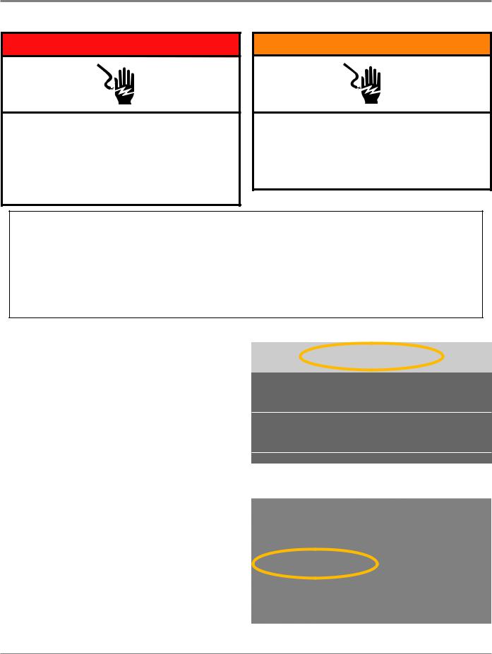
DIAGNOSTICS & TROUBLESHOOTING
Whirlpool LCD in Door Diagnostics
 DANGER
Electrical Shock Hazard
Only authorized technicians should perform diagnostic voltage measurements.
After performing voltage measurements, disconnect power before servicing.
Failure to follow these instructions can result in death or electrical shock.
 WARNING
Electrical Shock Hazard Disconnect power before servicing.
Replace all parts and panels before operating.
Failure to do so can result in death or electrical shock.
Voltage Measurement Safety Information
When performing live voltage measurements, you must do the following:
Verify the controls are in the off position so that the appliance does not start when energized.
Allow enough space to perform the voltage measurements without obstructions.
Keep other people a safe distance away from the appliance to prevent potential injury.
Always use the proper testing equipment.
After voltage measurements, always disconnect power before servicing.
SERVICE DIAGNOSTIC MODE TESTS
NOTE: The Service Diagnostic Mode must be activated before performing the tests; see procedure on page 2-9.
The following section describes components that may be manually turned on and off to help with troubleshooting certain issues.
IMPORTANT: Turn off power or disconnect washer before attaching test leads. Be sure test leads are attached prior to component activation.
To check voltage measurements, the following steps must be followed:
1.Unplug washer or disconnect power.
2.Connect voltage measurement equipment to appropriate connectors.
3.Plug in washer or reconnect power and confirm voltage reading.
4.After performing voltage measurements, unplug washer or disconnect power.
Active Fault Code Display in Quick Service Cycle
If the display begins flashing while running a Quick Service Cycle, it is displaying an active fault code. Active fault codes are codes that are currently being detected. Only one active fault code can be displayed at a time.
From the DIAGNOSTICS HOME screen:
< |
DIAGNOSTICS HOME |
Error Diagnostic
Clear Error History
Figure 1
Scroll down and select “Component Activation”
Figure 2
Continued on following page . . .
2-10 n Whirlpool & Maytag Front-Load Washers

DIAGNOSTICS & TROUBLESHOOTING
Whirlpool LCD in Door Diagnostics
SERVICE DIAGNOSTIC MODE TESTS (Continued)
Component Activation
The Component Activation screen includes a list of loads that can be tested. Select the appropriate row and touch once to toggle the load ON, touch again to toggle OFF.
NOTE: The door will lock whenever a load is turned ON. The door will unlock when the load is turned OFF.
Scroll down and select the component as follows:
IMPORTANT: Activate only one component at a time.
•Turn “Cold 1 Valve ON” On– confirm voltage measurement
•Turn “Cold 1 Valve ON” Off
•Turn “Cold 2 Valve ON” On – confirm voltage measurement
•Turn “Cold 2 Valve ON” Off
•Turn “Spin LowSpeed” On – confirm voltage measurement
•Turn “Spin LowSpeed” Off
•Turn “Spin HighSpeed” On – confirm voltage measurement
•Turn “Spin HighSpeed” Off
IMPORTANT: Drum will spin to 830 RPM. Ensure nothing is in the drum.
•Turn “Add min. water level, Turn on Heater” On - confirm voltage measurement (On Some Models)
•Turn “Add min. water level, Turn on Heater” Off
IMPORTANT: Washer will add a minimal water level, then turn on the heater.
“On Some Models”
|
Figure 5 |
|
Figure 3 |
• Turn “Dry Heater* and Combo Fan” On – confirm voltage |
|
• Turn “Hot Valve ON” On – confirm voltage measurement |
measurement |
|
• Turn “Dry Heater* and Combo Fan” Off |
||
• Turn “Hot Valve ON” Off |
||
*IMPORTANT: The “Dry Heater Element” has been deactivated |
||
|
||
|
on the LCD in Door diagnostics. Only the “Fan” will be activated. |
|
• Turn “Drain Pump” On – confirm voltage measurement |
|
|
• Turn “Drain Pump” Off |
• Turn “Detergent Pump” On – confirm voltage measurement |
|
|
• Turn “Detergent Pump” Off |
|
• Turn “Recirculation Pump” On – confirm voltage |
|
|
measurement |
• Turn “Softener Pump” On – confirm voltage measurement |
|
• Turn “Recirculation Pump” Off |
||
• Turn “Softener Pump” Off |
||
|
*See important note above
Figure 4
Figure 6
Continued on following page . . .
Whirlpool & Maytag Front-Load Washers n 2-11
Loading...