

®
Heating ¡ Air Conditioning
A higher standard of comfort
MODELS
PGC(24-60)B and
PGB58B
Table of Contents
I. Unit Specifications ........................................ 2
II. Safety Information ......................................... 6
III. General Information ...................................... 7
IV. Rigging and Handling ................................... 9
V. Gas Piping .................................................... 10
Vl. Electrical Wiring .......................................... 12
Vll. Circulating Air and Filters .......................... 13
VIII. Flue Vent ....................................................... 16
IX. Condensate Drain ........................................ 16
X. Heating Sequence of Operations............... 18
XI. Cooling Sequence of Operations .............. 18
XIl. Startup and Adjustment .............................. 18
XIII. Maintenance................................................. 24
XIV. Accessories and Functional Parts ............ 26
XV. Typical Cooling Performance Data ............ 27
XVI. Wiring Diagram ............................................ 29
Gas-Electric Package
Unit
Cooling and Heating
Installation Instructions
RECOGNIZE THIS SYMBOL AS A SAFETY PRECAUTION
ATTENTION INSTALLING PERSONNEL
As a professional installer you have an obligation to
know the product better than the customer. This includes all safety precautions and related items.
Prior to actual installation, thoroughly familiarize yourself with this Instruction Manual. Pay special attention to all safety warnings. Often during installation or
repair it is possible to place yourself in a position which
is more hazardous than when the unit is in operation.
Affix These Installation Instructions Adjacent To The Appliance.
Remember, it is your responsibility to install the
product safely and to know it well enough to be able
to instruct a customer in its safe use.
Safety is a matter of common sense...a matter of thinking before acting. Most dealers have a list of specific
good safety practices...follow them.
The precautions listed in this Installation Manual
should not supersede existing practices but should
be considered as supplemental information.
Amana
May 1998 (2) 11073904
Fayetteville, TN 37334

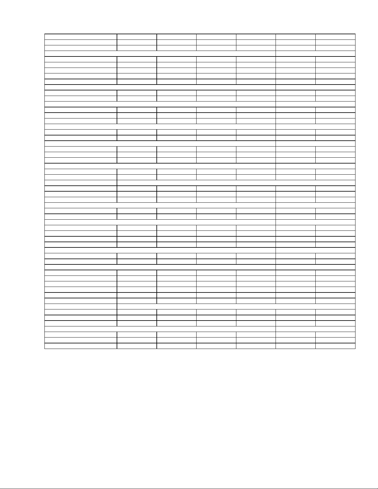
I. Unit Specifications
MODEL PGC24B0452A PGC24B0702A PGC30B0702A PGC36B0702A PGC36B09 02A
Cooling Cap acity Btuh 24,000 24,000 30,000 36,000 36,000
SEER 12.50 12.50 12.30 12.00 12.00
Heating
Input Btuh 45,000 70,000 70,000 70,000 90,000
Output Btuh 35,000 55,000 55,000 55,000 70,000
AFUE 80.9 80.1 80.1 80.1 80.4
Temperature Rise °F 20-50 30-60 30- 60 30-60 40-70
Number of Burn er s 2 3 3 3 4
Compressor
R.L. Amps 12.9 12.9 15 20 20
L.R. Amps 62.5 62.5 76 90.5 90.5
Condenser Coil
Face Area (sq. ft.) 12.3 12.3 12.3 14 14
Rows Deep 1 1/2 1 1/2 2 2 2
Fins/Inch 13 13 13 13 13
Condenser Fan
Diameter (in.) 20 20 20 20 20
CFM 2670 2670 2700 3060 3060
Condenser Fan Motor
Horsepower 1/8 1/8 1/4 1/4 1/4
R.L. Amps 0.8 0.8 1.2 1.5 1.5
L.R. Amps 1.5 1.5 3 3.4 3.4
Blower M o to r
Horsepower 0.5 0.5 0.5 0.5 0. 5
R.L. Amps 4.3 4.3 4.3 4.3 4.3
L.R. Amps Protected by redundant electronic control circuits
Blower Wh eel Dia. x Width (in .) 10x7 10x7 10x7 10x7 10x7
Rated CFM, Cooling 850 850 1100 1300 1300
Max. External 0.8" wc 0.8" wc 0.8" wc 0.8" wc 0.8" wc
Combustion Blower
Diameter x Wi d th (in.) 4 x 1.25 4 x 1.25 4 x 1.25 4 x 1.25 4 x 1.25
No. 11111
Condenser Blower Motor
H.P. 0.03125 0.03125 0.03125 0.031 25 0.03125
F.L. Amps. 0.5 0.5 0.5 0.5 0.5
Press. Switch S ett in g (" W.C.) -0.65 -0.65 -0.65 -0.65 -0.65
Ignition - Lockout Timing (sec.) 4 4 4 4 4
Flame Sense Current (microamps)
Minimum 11111
Maximum 66666
Evaporator Coil
Face Area (Sq. Ft.) 4 4 4 4 4
Rows Deep 22244
Fins/Inch 16 16 16 12 12
External Filter Size (Sq. Ft.) 3.6 3.6 3.6 3.6 3.6
Drain Line Size (in.) 3/4 3/4 3/4 3/4 3/4
Expansion Device (Cooling) Capillary Capillary Capillary Capillary Capillary
Refrigerant Charge Refer to unit nam e p late for correct charg e
Power Supply** 208/230-60-1 208/230-60-1 208/230-60-1 208/230-60-1 208/230-60-1
Min. Circuit Ampacity 21.3 21.3 24.3 30.8 30.8
Max. Overcurre n t Device 30 30 35 45 45
Electrical Entrance Size
Power Supply 1 1/4", 1 1/2", 2" 1 1/4", 1 1/2", 2" 1 1/4", 1 1/2", 2" 1 1/4", 1 1/2", 2" 1 1/4", 1 1/2", 2"
Low Voltage 7/8" 7/8" 7/8" 7/8" 7/8"
Approx. Shipping Weight (lb.) 385 39 4 418 437 443
1) United States Installation
2) Specification subject to change without notice. See sales specification sheets for certain BTUH capacities.
3) This PGC series complies with requirements embodied in the American National Standard ANSI-Z21.47 Central Furnaces.
4) Filters are not supplied with units, but filters must be installed in the unit filter rack or in the return air system.
** While the above data is presented as a guide, it is important to electrically connect the unit and properly size overcurrent protection and wires in accordance with the
National Electrical Code and all existing local codes.
Operating tolerance: Minus 5% on 208 VAC, Plus 10% on 208 VAC and 230 VAC, Minus 10% on 230 VAC
Table 1A
Gas Pack Specifications
2
MODEL PGC42B0902A PGC42B1152A PGC48B0902A PGC48B1152A PGC60B0902A PGC60B1352A
Cooling Capacity Btuh 42,000 42,000 48,000 48,000 60,000 60,000
SEE R 12.20 12.20 12.00 12.00 12.00 12.00
Heating
Compressor
Condenser Coil
Condenser Fan
Condenser Fan Motor
Blow er Mot or
Blower Wheel Dia. x W idth (in.) 10x10 10x10 10x10 10x10 11x8 11x8
Combustion Blower
Condenser Blower Motor
P ress. S wi t ch Setting (" W.C.) -0.65 -0 .65 -0.65 -0.65 -0 .65 -0.65
Ignition - Lockout Timing (sec.) 4 4 4 4 4 4
Flame Sense Current ( microamps)
Evaporator Coil
Electrical Entrance Size
Approx. Shipping Weight (lbs) 521 527 526 526 531 531
Input B tuh 90, 000 115,000 90,000 115,000 90,000 135,000
Output Btuh 72,000 89,000 72,000 89,000 72,000 108,000
AFUE 81.4 79.9 81.4 79.9 81.4 80.5
Temperature Rise °F 25-55 40-70 25-55 40-70 25-55 40-70
Number of Bu rners 4 5 4 5 5 6
R.L. Amps 22 22 21.8 21.8 28.8 28.8
L.R. Amps 107 107 105 105 169 169
Face Area (sq. ft.) 17.2 17.2 17.2 17.2 17.2 17.2
Rows Deep 222222
Fins/Inch 13 13 17 17 17 17
Diameter (in.) 242424242424
CFM 3500 3500 3700 3700 4700 4700
Horsepower 1/4 1/4 1/2 1/2 1/3 1/3
R .L. Amps 1.5 1.5 1.5 1.5 2.5 2.5
L.R. Amps 3.4 3.4 3.6 3.6 6.4 6.4
Horsepower 3/4 3/4 3/4 3/4 1 1
R.L. Amps 555577
L.R. Amps
Rated CFM, Cooling 1450 1450 1700 1700 1750 1750
Max. External 0.8" wc 0.8" wc 0.8" wc 0.8" wc 0.8" wc 0.8" wc
Diameter x Width (in.) 4 x 1.25 4 x 1.25 4 x 1.25 4 x 1.25 4 x 1.25 4 x 1.25
No. 111111
H.P . 0.03125 0.03125 0.03125 0.03125 0.03125 0.03125
F.L. Amps. 0.5 0.5 0.5 0.5 0.5 0.5
Minimum 111111
Maximum 666666
Face Area (Sq. Ft.) 5.7 5.7 5.7 5.7 5.7 5.7
Rows Deep 223333
Fins/Inch 15 15 15 15 15 15
External F ilter Size (Sq. Ft.) 5.3 5.3 5.3 5.3 5.3 5.3
Drain Line Size (in.) 3/4 3/ 4 3/4 3/4 3/4 3/4
Expansion Device (Cooling) Capillary Capillary TEV TEV TEV TEV
Refrigerant Charge Refer to unit name plate for correct charge
Power Supply** 208/230-60-1 208/230-60-1 208/230-60-1 208/230-60-1 208/230-60-1 208/230-60-1
Min. Circuit Ampacity 34 34 39.5 39.5 49.7 49.7
Max. Overcurrent Device 50 50 50 50 70 70
Power Supply 1 1/4", 1 1/2", 2" 1 1/4", 1 1/2", 2" 1 1/4", 1 1/2", 2" 1 1/4", 1 1/2", 2" 1 1/4", 1 1/2", 2" 1 1/4", 1 1/2", 2"
Low Voltage 7/8" 7/8" 7/8" 7/8" 7/8" 7/8"
Protected by redundant electronic control circuts
1) United States Installation
2) Specification subject to change without notice. See sales specification sheets for certain BTUH capacities.
3) This PGC series complies with requirements embodied in the American National Standard ANSI-Z21.47 Central Furnaces.
4) Filters are not supplied with units, but filters must be installed in the unit filter rack or in the return air system.
** While the above data is presented as a guide, it is important to electrically connect the unit and properly size overcurrent protection and wires in accordance with the
National Electrical Code and all existing local codes.
Operating tolerance: Minus 5% on 208 VAC, Plus 10% on 208 VAC and 230 VAC, Minus 10% on 230 VAC
Table 1B
Gas Pack Specifications
3
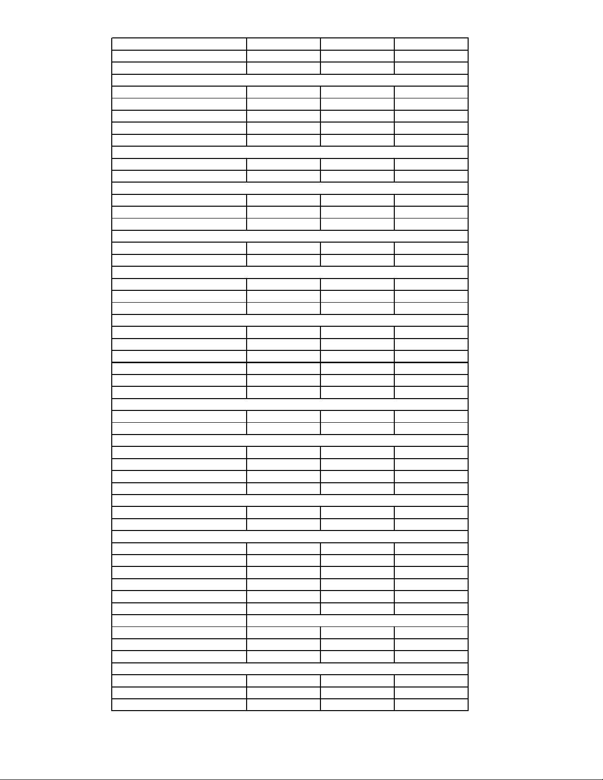
MODEL PGB58B0902A PGB58B1152A PGB58B1352A
Cooling Capacity Btuh 59,500 59,500 59,500
SEER 11.10 11.10 11.10
Heating
Input Btuh 90,000 115,000 135,000
Output Btuh 72,000 92,000 108,000
AFUE 81.4 79.9 80.5
Temperature Rise °F 25-55 25-55 25-55
Number of Burners 4 4 4
Compressor
R.L. Amps 28.8 28.8 28.8
L.R. Amps 169 169 169
Condenser Coil
Face Area (sq. ft.) 17.2 17.2 17.2
Rows Deep 2 2 2
Fins/Inch 17 17 17
Condenser Fan
Diameter (in.) 24 24 24
CFM 4700 4700 4700
Condenser Fan Motor
Horsepower 1/3 1/3 1/3
R.L. Amps 2.5 2.5 2.5
L.R. Amps 6.4 6.4 6.4
Blower Motor
Horsepower 3/4 3/4 3/4
R.L. Amps 5.6 5.6 5.6
L.R. Amps 12.9 12.9 12.9
Blower Wheel Dia. x Width (in.) 11X8 11X8 11X8
Rated CFM, Cooling 1750 1750 1750
Max. External 0.5" wc 0.5" wc 0.5" wc
Combustion Blower
Diameter x Width (in.) 4 x 1.25 4 x 1.25 4 x 1.25
No. 111
Condenser Blower Motor
H.P. 1/32 1/32 1/32
F.L. Amps. 0.5 0.5 0.5
Press. Switch Setting (" W.C.) -0.65 -0.6 5 -0.65
Ignition - Lockout Timing (sec.) 4 4 4
Flame Sense Current (microamps)
Minimum 111
Maximum 666
Evaporator Coil
Face Area (Sq. Ft.) 5.7 5.7 5.7
Rows Deep 4 4 4
Fins/Inch 15 15 15
External Filter Size (Sq. Ft.)
Drain Line Size (in.) 3/4 3/4 3/4
Expansion D evice (Cooling) TEV TEV TEV
Refrigerant Charge Refer to unit name plate for correct charge
Power Supply** 208/230-60-1 208/230-60-1 208/230-60-1
Min. Circuit Ampacity 33.75 33.75 33.75
Max. Overcurrent Device 50 50 50
Electrical Entrance Size
Power Supply 1 1/4", 1 1/2", 2" 1 1/4", 1 1/2", 2" 1 1/4", 1 1/2", 2"
Low Voltage 7 /8" 7/8" 7/8"
Approx. Shippi ng Weight (lbs) 531 531 531
Table 1C
Gas Pack Specifications
4
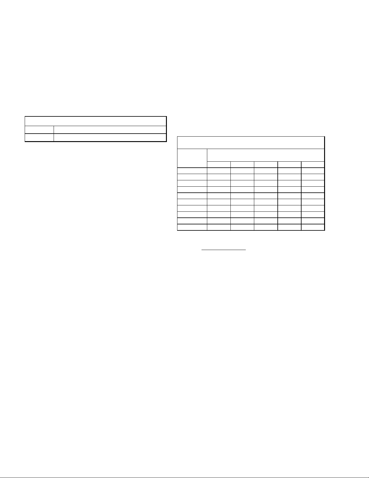
Nominal
Model
PGC24B0452A 24000 850 45000 930 570 35 A A
PGC24B0702A 24000 850 70000 1140 570 45 A B
PGC30B0702A 30000 1100 70000 1140 570 45 B B
PGC36BO702A 36000 1300 70000 1140 570 45 C B
PGC36B0902A 36000 1300 90000 1350 570 55 C C
PGC42B0902A 42000 1450 90000 1650 815 40 A A
PGC42B1152A 42000 1450 115000 1530 815 55 A B
PGC48B0902A 48000 1700 90000 1650 815 40 B A
PGC48B1152A 48000 1700 115000 1530 815 55 B B
PGC60B0902A 60000 1750 90000 1650 815 40 A A
PGC60B1352A 60000 1750 135000 1900 815 55 A B
1. Installation is to be adjusted to obtain temperature rise within the range specified on the rating plate.
2. The temperature rise is for units installed at 0-2000 feet. At higher altitudes, a properly derated unit will have
approximately the same temperature rise and CFM.
3. The chart is applicable for both vertical and horizontal airflow.
4. All speed tap settings are factory selected according to unit size.
5. Data shown without filters. Consult filter manufacturer for pressure drop to be added.
6. Motor is constant CFM for external static pressures 0.1" to 0.8" W.C.
7. Maximum External Pressure Limits
PGC 24-42 0.8" W.C.
PGC46 & 60 1.0 W.C.
Cooling Nominal
Capacity
(MBh)
Cooling
CFM
(Y+G) (W1) (G) Cool Heat
Nominal
Heating Nominal Nominal Temp. Speed
Capacity
(Input)
Heating
CFM
Fan Only Rise (°F) Taps
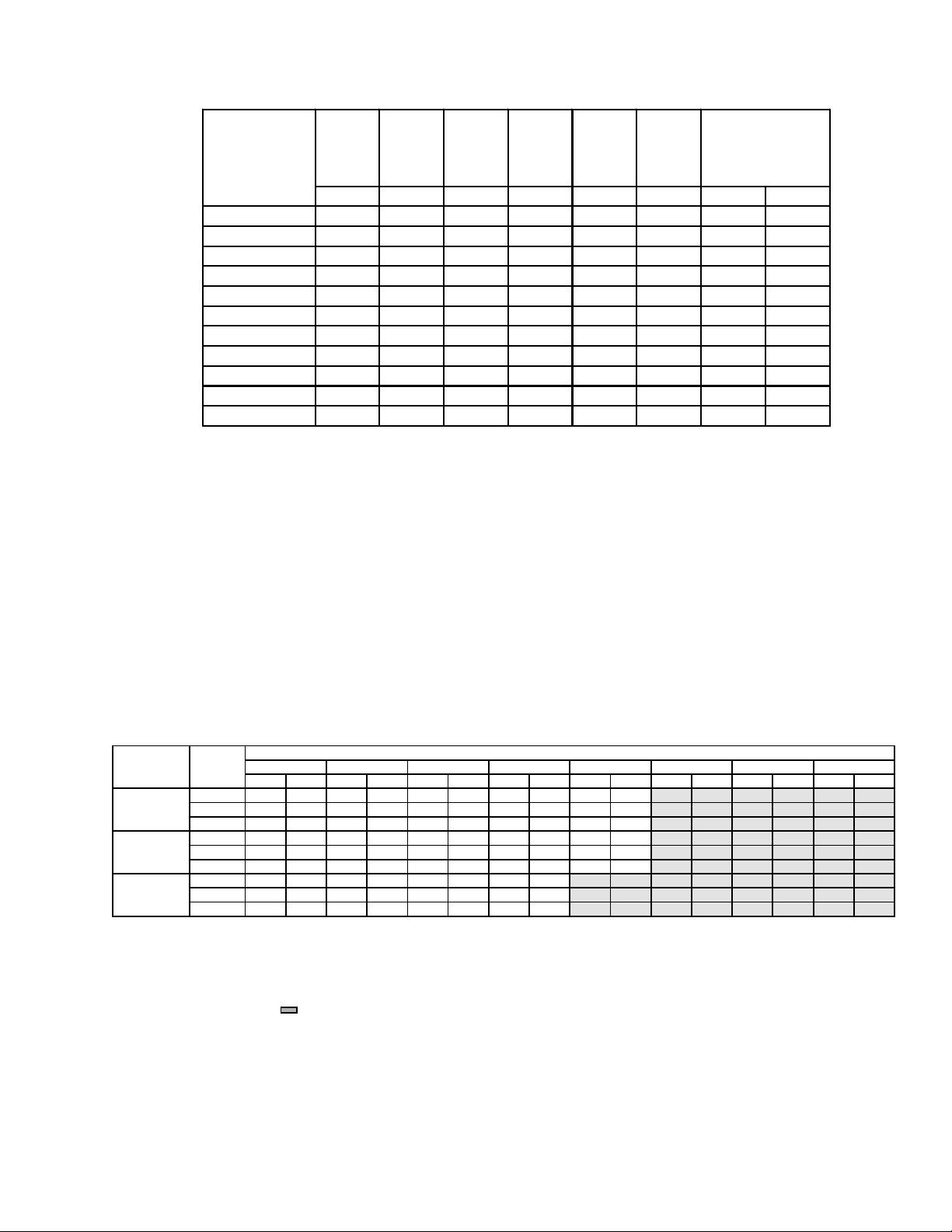
Table 2A
PGC Temperature Rise Table
Model Speed CFM RISE CFM RISE CFM RISE CFM RISE CFM RISE CFM RISE CFM RISE CFM RISE
Motor 0.1 0.2 0.3 0.4 0.5 0.6 0.7 0.8
Hi 2160 31 2120 31 2080 32 2030 33 1990 34 1945 34 1900 35 1835 36
PGB58B0902C Med 1750 38 1750 39 1700 39 1680 40 1680 40 1615 41 1575 42 1490 45
Lo 1490 45 1480 45 1470 45 1450 46 1440 46 1415 47 1360 49 1280 52
Hi 2160 --- 2120 --- 2080 41 2030 42 1990 43 1945 44 1900 45 1835 46
PGB58B1152C Med 1750 49 1750 49 1700 50 1680 51 1650 52 1615 53 1575 54 1470 57
Lo 1490 57 1480 58 1470 58 1460 58 1440 59 1415 60 1360 63 1280 67
Hi 2160 46 2120 47 2080 48 2030 49 1990 50 1945 51 1900 53 1835 54
PGB58B1352C Med 1750 57 1750 58 1700 59 1680 60 1650 61 1615 62 1575 63 1490 67
Lo 1490 67 1480 68 1470 68 1460 68 1440 69 1415 --- 1360 --- 1280 ---
NOTE:
1. All airflow is dry coil.
2. Installation is to be adjusted to obtain temperatures rise within the range specified on the rating plate.
3. The above chart is for information only. For satisfactory operation, external static pressure should not exceed value shown on the rating
plate. The shaded area ( ) indicates in excess of maximum external static pressure allowable when heating.
4. This chart is for units installed at 0-2000 feet. At higher altitudes, a properly derated unit will have approximately the same temperature
rise at a particular CFM, while ESP at that CFM will be lower.
5. Cooling operation may require a different fan speed than heating operation. For details, see Wiring Diagrams.
6. Above chart is applicable for both vertical and horizontal airflow.
External Static Pressure, Inches Water Column
Table 2B
PGB CFM& Temperature Rise vs. External Static Pressure Table
5
II. Safety Information
WARNING
Important
To The Installer
Before installing this unit please read this manual to familiarize yourself with the specific items which must be
adhered to such as maximum external static pressure
to unit, air temperature rise, minimum or maximum CFM
and motor speed connections. Affix these Installation
Instructions adjacent to the appliance.
To The Owner
It is important that you complete the owner registration
card and mail it today. This will assist Amana in contacting you if any service or warranty information should
change in the future. When completing the registration
card, be sure to include the Model, Manufacturing and
Serial Numbers, plus the installation date.
Your warranty certificate is also supplied with the unit.
Read the warranty carefully and note what is covered.
Keep the warranty certificate in a safe place so you can
find it if necessary.
If additional operating Instructions are required, call the
dealer where the purchase was made. Keep this literature in a safe place for future reference.
Do not store gasoline or other flammable
vapors and liquids in the vicinity of this
or any other appliance.
If you smell gas:
• Extinguish any open flame.
• Do not try to light appliance.
• Do not touch any electrical switch: do not use any
phone in building.
• Immediately call gas supplier from a neighbor’s
phone. Follow gas supplier’s instructions.
• If gas supplier cannot be reached, call fire depart-
ment.
WARNING
Improper installation, adjustment, alterations, service or maintenance can cause
property damage, personal injury, or
death. Follow all procedures in this
manual. For assistance or additional information, contact a qualified installer,
service agency, or gas supplier.
WARNING
Should overheating occur or the gas supply fail to shut off, turn off the manual
gas control valve to the furnace before
shutting off the electrical supply.
CAUTION
On PGC48 - 60 and PGB58 Only: To avoid
damage to the compressor, engage the
electrical disconnect switch to the compressor unit four hours prior to operating air conditioner after the electrical disconnect is off for a prolonged period of
time (during vacation, etc.). This time
lapse allows the compressor crankcase
to attain a proper operating temperature.
WARNING
If the information in this manual is not
followed exactly, a fire or explosion may
result causing property damage, personal injury, or death.
WARNING
This product contains or produces a
chemical(s) which may cause death or
serious illness and which are known by
the State of California to cause cancer,
birth defects or other reproductive harm.
CAUTION
This unit should not be used as a “construction heater” during the finishing
phases of construction on a new structure. This type of use may result in premature failure of the unit due to extremely
low return air temperatures and exposure
to very dirty atmospheres.
6
Locating The Unit
WARNING
To avoid possible equipment damage,
fire, personal injury, or death, the following points must be observed when installing the unit.
All Installations:
• For proper flame pattern within the heat exchanger
and proper condensate drainage, the unit must be
mounted level.
• The unit should be as centralized as is practical with
respect to the air distribution system. This unit is for
outdoor installation ONLY!
• The flue outlet hood must be at least 12 inches from
any opening through which flue gases could enter a
building, and at least three feet above any forced air
inlet located within ten feet. The economizer/manual
outdoor air intake/motorized outdoor air intake and
combustion air inlet mounted on the unit are not affected by this restriction.
• To avoid possible corrosion of the heat exchanger,
do not locate the unit in an area where the outdoor
air (i.e., combustion air for the unit) will be frequently
contaminated by compounds containing chlorine or
fluorine. Common sources of such compounds include swimming pools and chlorine bleaches, paint
stripper, adhesives, paints, varnishes, sealers,
waxes (which are not yet dried) and solvents used
during construction and remodeling. Various commercial and industrial processes may also be
sources of chlorine/fluorine compounds.
• To avoid possible illness or death of the building oc-
cupants, do NOT locate outside air intake device
(economizer, manual outdoor air intake, motorized
outdoor air intake) too close to an exhaust outlet,
gas vent termination, or plumbing vent outlet. For
specific distances required, consult local codes.
• Allow clearances from the enclosure as shown in
Figure 1 for fire protection, proper operation, and
service access. These clearances must be permanently maintained.
• The combustion air inlet and flue outlet hoods on
the front of the unit must never be obstructed. If used,
do not allow the economizer/manual outdoor air
damper/ motorized outdoor air damper to become
blocked by snow or debris. In some climates or locations, it may be necessary to elevate the unit to
avoid these problems.
• When the unit is heating, the temperature of the re-
turn air entering the unit must be between 50° F and
100° F.
Ground Level Installations Only:
• When the unit is installed on the ground adjacent to
the building, a level concrete (or equal) base is recommended. Prepare a base the same physical size
as the unit or slightly larger and 3 inches thick.
• The base should also be located where no run-off
of water from higher ground can collect in the unit.
• The feet on the unit may not be removed.
Rooftop Installations Only:
• To avoid possible property damage or personal injury, the roof must have sufficient structural strength
to carry the weight of the unit(s) and snow or water
loads as required by local codes.
• If horizontal air delivery is used, the unit may be installed directly on wood floors or on Class A, Class
B, or Class C roof covering material, provided that
the feet on the unit are not removed.
• To avoid possible personal injury, a safe, flat surface for service personnel should be provided.
• If vertical air discharge is used and the unit is installed on combustible flooring or class A, B, or C
roofing material, then the Amana roof curb (PRC3A
or PRC5A) listed on the unit nameplate is required.
III. General Information
WARNING
Improper installation, repair, operation or
maintenance of this product may result
in property damage, personal injury, or
death from hazards such as fire, explosions, smoke, soot, condensation, electric shock or carbon monoxide.
This unit is approved only for an outdoor installation. To
assure that your unit operates safely and efficiently, it
must be installed, operated, and maintained in accordance with these installation and operating instructions,
all local building codes and ordinances, or in their absence, with the latest edition of the National Fuel Gas
Code. (ANSI Z223.1).
The heating and cooling capacities of the unit should be
greater than or equal to the design heating and cooling
loads of the area to be conditioned. The loads should
be calculated by an approved method or in accordance
with ASHRAE Guide or Manual J - Load Calculations
published by the Air Conditioning Contractors of America.
Obtain from:
American National Standards Institute
1430 Broadway
New York, NY 10018
7
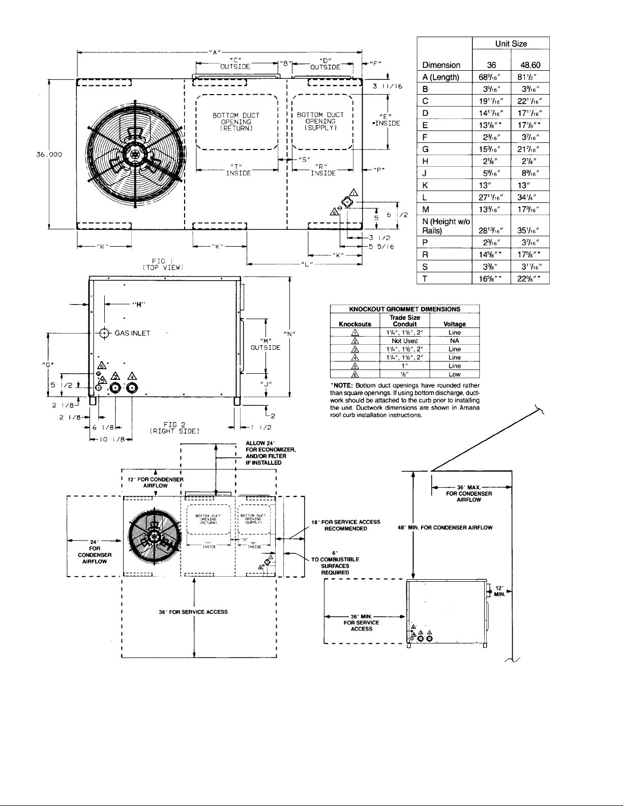
Figure 1
Required Clearances For All Installations
8
Transportation Damage
All units are securely packed in shipping cartons approved by the International Safe Transit Association. The
carton should be checked upon arrival for external damage. If damage is found, a request for inspection by carrier agent should be made in writing immediately.
The unit should be carefully inspected upon arrival for
damage and bolts or screws which may have loosened
in transit. In the event of damage, the consignee should:
1. Make notation on delivery receipt of any visible damage to shipment or container.
2. Notify carrier promptly and request an inspection.
3. In case of concealed damage, carrier should be notified as soon as possible-preferably within 5 days.
4. File the claim with the following supporting documents within the 9-month statute of limitations.
a. Original Bill of Lading, certified copy, or indemnity
bond.
b. Original paid freight bill or indemnity in lieu thereof.
c. Original invoice or certified copy thereof, showing
trade and other discounts or reductions.
d. Copy of the inspection report issued by carrier
representative at the time damage is reported to
the carrier. The carrier is responsible for making
prompt inspection of damage and for a thorough
investigation of each claim. The distributor or
manufacturer will not accept claims from dealers
for transportation damage.
NOTE: When inspecting the unit for transportation damage, remove all packaging materials. Follow local codes
when disposing or recycling the packaging material.
IV. Rigging and Handling
CAUTION
To prevent possible property damage, the
unit should remain in an upright position
during all rigging and moving operations.
To facilitate lifting and moving when a
crane is used, place the unit in an adequate cable slide.
Important: If using bottom discharge with roof curb,
ductwork should be attached to the curb prior to installing the unit. Ductwork dimensions are shown in Amana
Roof Curb Installation Instructions.
Refer to the Amana Roof Curb Installation Instructions
for proper curb installation. Curbing must be installed in
compliance with the National Roofing Contractors Association Manual.
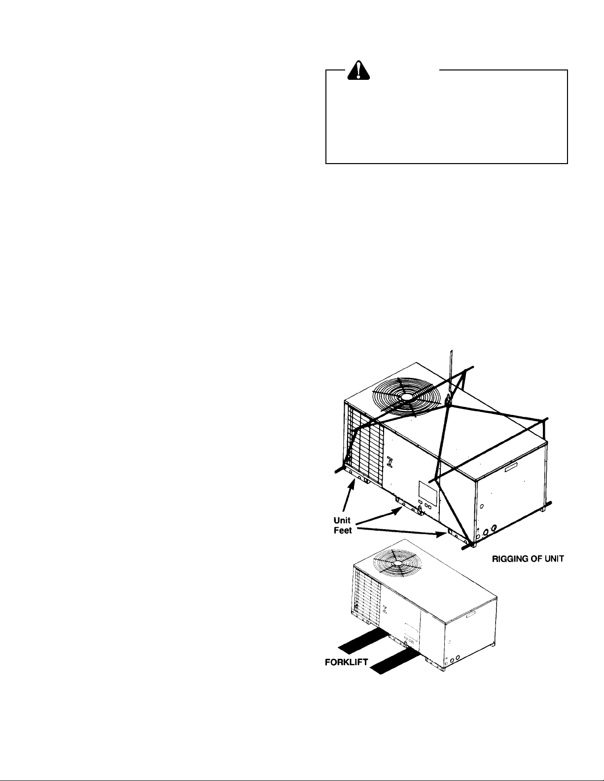
Lower unit carefully onto roof mounting curb. While rigging unit, center of gravity will cause condenser end to
be lower than supply air end.
If using a fork lift, see Figure 2 for location of fork prongs.
Make certain prongs support unit weight.
Locating The Thermostat
The thermostat should be mounted 5 feet above the floor,
on a vibration free inside wall in a room or a hallway that
has good air circulation.
Movement of air should not be obstructed by furniture,
door, draperies, etc. The thermostat should not be
mounted where it will be affected by drafts, hot or cold
water pipes or air ducts in walls, radiant heat from fireplace, lamps, the sun, television, etc. Consult the Instruction Sheet packaged with the thermostat for mounting instructions.
All units have one stage of heating and one stage of
mechanical cooling. Units which will have economizers
may use thermostats with one or two stages of cooling.
Figure 2
Rigging
9
V. Gas Piping
IMPORTANT NOTE: This furnace is factory set to oper-
ate on natural gas at the altitudes shown on the rating
plate. If operation at higher altitudes and/or propane gas
operation is required, obtain and install the proper conversion kit(s) before operating this furnace. Failure to
do so may result in unsatisfactory operation and/or equipment damage. (High altitude kits are for U.S. installations only.)
The rating plate is stamped with the model number, type
of gas and gas input rating. Make sure the furnace is
equipped to operate on the type of gas available.
INL ET GA S PRESSURE
Natural Min. 5.0" W.C., Max. 10.0" W.C.
Propane Min. 11.0" W. C. , M ax . 14. 0" W. C.
Inlet Gas Pressure Must Not Exceed the Maximum Value Shown
in Table 3.
Table 3
The minimum supply pressure should not vary from that
shown in the table above because this could prevent
the furnace from having dependable ignition. In addition, gas input to the burners must not exceed the rated
input shown on the rating plate. Overfiring of the furnace could result in premature heat exchanger failure.
High Altitude Derate (US. Installations Only Canadian Installations to 4500 Feet Only)
When this furnace is installed at altitudes above 2000
feet, the furnace input must be derated 4% for each 1000
feet above sea level because the density of the air is
reduced.
In some areas the gas supplier will derate the heating
value of the gas at a rate of 4% for each 1000 feet above
sea level. If this is not done, smaller orifices will be required at altitudes above 3500 feet (non-derated natural gas) or 4500 feet (non-derated propane gas).
A different pressure switch will be required at altitudes
more than 4000 feet above sea level. This is required
regardless of the heat content of the fuel used.
High altitude kits can be purchased depending on the
altitude and usage of propane or natural gas. Refer to
the high altitude instruction manual included with this
furnace to determine which high altitude components to
use.
Adjustment of the manifold pressure to a lower pressure reading than what is specified on the furnace nameplate is not a proper derate procedure. With a lower density of air and a lower manifold pressure at the burner
orifice, the orifice will not aspirate the proper amount of
air into the burner. This can cause incomplete combustion of the gas, flashback, and possible yellow tipping.
Gas Piping
IMPORTANT NOTE: To avoid possible unsatisfactory
operation or equipment damage due to under firing of
equipment, do not undersize the natural gas/propane
piping from the meter/tank to the furnace. When sizing
a trunk line as shown in Table 4, include all appliances
on that line that could be operated simultaneously.
The rating plate is stamped with the model number, type
of gas and gas input rating. Make sure the furnace is
equipped to operate on the type of gas available.
The gas line installation must comply with local codes,
or in the absence of local codes, with the latest edition
of the National Fuel Gas Code (ANSI Z223.1).
Connecting The Gas Piping - Natural Gas
Natural Gas Capacity of Pipe
in Cubic Feet of Gas Per Hour (CFH)
Length of
Pipe in Feet 1/2 3/4 1 1 1/4 1 1/2
10 132 278 520 1050 1600
20 92 190 350 730 1100
30 73 152 285 590 980
40 63 130 245 500 760
50 56 115 215 440 670
60 50 105 195 400 610
70 46 96 180 370 560
80 43 90 170 350 530
90 40 84 160 320 490
100 38 79 150 305 460
Press u re = .5 0 PSIG or l e ss and Pres sure Drop of 0.3" W .C. (Bas e d
Btuh Furnace Input
CFH=
Calorific Value of Gas
Nominal Black Pipe Si ze (inches)
on 0. 60 Spec ific G ravity Ga s)
Table 4
Refer to Figure 3 for the general layout at the furnace.
The following rules apply:
1. Use black iron or steel pipe and fittings for the building piping.
2. Use pipe joint compound on male threads only. Pipe
joint compound must be resistant to the action of
the fuel used.
3. Use ground joint unions.
4. Install a drip leg to trap dirt and moisture before it
can enter the gas valve. The drip leg must be a minimum of three inches long.
5. Use two pipe wrenches when making connection to
the gas valve to keep it from turning.
6. Install a manual shut-off valve in a convenient location (within six feet of unit) between the meter and
the unit.
7. Tighten all joints securely.
10

Figure 3
Proper Piping Practice
WARNING
To avoid personal injury or property damage, be sure there is no open flame in the
vicinity during air bleeding procedure.
There will be air in the gas supply line after testing for
leaks on a new installation. Therefore, the air must be
bled from the line by cracking open the ground joint union
until pure gas is expelled. Tighten union and wait for
five minutes until all gas has been dissipated in the air.
Be certain there is no open flame in the vicinity during
air bleeding procedure. The unit is placed in operation
by closing the main electrical disconnect switch for the
furnace.
Tanks And Piping for Propane Gas Units
Checking The Gas Piping
CAUTION
To avoid the possibility of personal injury, property damage or fire, the following instructions must be performed regarding gas connections and pressure
testing:
• This unit and its gas connections must
be leak tested before placing in operation. Because of the danger of explosion
or fire, never use a match or open flame
to test for leaks. Never exceed specified pressures for testing. Higher pressure may damage gas valve and cause
overfiring which may result in heat failure.
• This unit and shut-off valve must be disconnected from the gas supply during
any pressure testing of that system at
test pressures in excess of 1/2 PSIG
(3.48 kPa).
• This unit must be isolated from the gas
supply system by closing the manual
shut-off valve during any pressure testing of the gas supply piping system at
test pressures equal to or less than 1/2
PSIG (3.48 kPa).
WARNING
Personal Injury Hazard
Failure to detect a propane gas leak could
result in an explosion or fire which could
cause death, serious personal injury, or
property damage.
Iron oxide (rust) can reduce the level of
odorant in propane gas. A gas detecting
device is the only reliable method to detect a propane gas leak. Contact the local propane supplier about installing a
warning device to sound an alert if a gas
leak should develop.
All propane gas equipment must conform to the safety
standards of the National Board of Fire Underwriters (See
NBFU Manual 58).
For satisfactory operation, propane gas pressure must
be 10 inch W.C. at the furnace manifold with all gas appliances in operation. Maintaining proper gas pressure
depends on three main factors:
1. Vaporization rate, which depends on (a) temperature of the liquid, and (b) wetted surface area of the
container or containers.
2. Proper pressure regulation. (Two-stage regulation
is recommended from the standpoint of both cost
and efficiency.)
3. Pressure drop in lines between regulators, and between second stage regulator and the appliance.
Pipe size required will depend on length of pipe run
and total load of all appliances.
Complete information regarding tank sizing for vaporization, recommended regulator settings and pipe sizing is available from most regulator manufacturers and
propane gas suppliers.
11

Special pipe dope must be used when assembling piping for this gas as it will quickly dissolve white lead or
most standard commercial compounds. Shellac base
compounds resistant to the actions of liquefied petroleum gases such as Gasolac, Static, Clyde or John
Crane are satisfactory.
Please refer to Figure 4 for typical propane gas installations.
Figure 4
Typical Propane Gas Piping
WARNING
Failure to follow the instructions on Page
6 of this manual when the presence of
gas is suspected could result in death or
serious personal injury. An undetected
gas leak would create a danger of explosion or fire.
If the propane gas furnace is installed in
an excavated area or a confined space, it
is strongly recommended contacting a
propane gas supplier about installing a
warning device to warn of a gas leak.
Propane gas is heavier than air and any
leaking gas can settle in low areas or
confined areas.
Propane gas odorant may fade, making
the gas undetectable except with a
warning device.
Vl. Electrical Wiring
WARNING
To avoid personal injury or death due to
electrical shock, disconnect the electrical power before electrically connecting
the unit.
The units are designed for operation on 60 hertz current
and at voltages as shown on the rating plate. All internal
wiring in the unit is complete. It is necessary to bring in
the power supply to the contactor as shown on the unit
wiring diagram which is supplied with each unit. The 24V
wiring must be connected between the unit control panel
and the room thermostat. Refer to Figure 5 for location
of low voltage terminal board and Figure 6 for proper
thermostat wiring.
Table 5
Propane Pipe Sizing
Low Voltage
Board
Figure 5
Low Voltage Control Box
12

Please refer to the unit wiring diagram for electrical connections. When installed, the unit must be electrically
grounded in accordance with local codes or in the absence of local codes with the latest edition of National
Electrical Code, ANSI/NFPA No. 70.
WARNING
To avoid death or personal injury due to
electrical shock, wiring to the unit must
be properly grounded.
CAUTION
To avoid personal injury or property damage due to fire, use only copper conductors.
The best protection for the wiring is the smallest fuse or
breaker which will hold the equipment on the line during
normal operation without nuisance trips. Such a device
will provide maximum circuit protection. DO NOT EXCEED THE MAXIMUM OVERCURRENT DEVICE SIZE
SHOWN ON UNIT DATA PLATE.
Be sure line voltage connections are made through
weatherproof fittings. All exterior power supply and
ground wiring must be in approved weatherproof conduit. Low voltage wiring from the unit control panel to
the thermostat requires coded cable. For ground level
and rooftop wiring refer to Figure 8.
CAUTION
To prevent improper and dangerous operation due to wiring errors, label all wires
prior to disconnection when servicing
controls. Verify proper operation after
servicing.
Vll. Circulating Air and Filters
Airflow Conversion
Units can easily be converted from horizontal to vertical
airflow delivery.
Units will ship from the factory ready for horizontal airflow. If conversion to vertical airflow is necessary, proceed as follows:
IMPORTANT: Be sure to save the flue hood assembly
(cardboard box) which is shipped in the return air compartment of the unit.
• Remove panels from the bottom of the unit, saving
the mounting screws.
• Remove insulation from outside of supply duct cover.
No insulation should face outside.
• Relocate the panels on to the side of the unit, se-
curing with the screws removed earlier.
• The unit will deliver the same amount of air whether
the airflow is vertical or horizontal. For details, see
the fan tables on Pages 2 - 5.
Unit Voltage
The unit transformer is factory connected for 230V operation. If the unit is to operate on 208V, reconnect the
transformer primary lead and induced draft blower motor leads as shown on the unit wiring diagram.
Heat Anticipator Setting
The heat anticipator in the room thermostat must be
correctly adjusted to obtain the proper number of heating cycles per hour and to prevent the room temperature from overshooting the room thermostat setting. Heat
anticipator must be set at 0.8 amps.
Figure 6
Typical Thermostat and Unit 24 V Wiring
Hookup
Figure 7
Airflow Conversion
Ductwork
CAUTION
To avoid possible fire, the cardboard
shipping support (located behind the
supply panel) must be removed before
operation.
IMPORTANT: Be sure to save the flue hood assembly
which is shipped in a cardboard box in the return air
compartment of the unit.
13

Typical Wiring
(Ground Level)
Disconnect Switch
High Voltage Source
High Voltage
Entrance
Low Voltage
Entrance
Rooftop
Curb
Junction
Box
Low Voltage
Entrance
Typical Wiring
(Rooftop)
Disconnect Switch
High Voltage Source
High Voltage
Entrance
Figure 8
Typical Electrical Wiring
14

Duct systems and register sizes must be properly designed for the C.F.M. and external static pressure rating
of the unit. Ductwork should be designed in accordance
with the recommended methods of Air Conditioning Contractors of America Manual D (Residential) or Manual Q
(Commercial). All ductwork exposed to the outdoors must
include a weatherproof barrier and adequate insulation.
A duct system should be installed in accordance with
Standards of the National Board of Fire Underwriters for
the Installation of Air Conditioning, Warm Air Heating
and Ventilating Systems, pamphlets No. 90A and 90B.
The warm air supply duct from the unit through a wall
fabricated of combustible material may be installed without clearance. However, minimum clearances for the unit
must be observed as shown in Section III.
It is recommended that the outlet duct be provided with
an access panel. This access should be large enough
to inspect the air chamber downstream from the heat
exchanger for any smoke or combustion gas leaks. A
cover should be tightly attached to prevent air leaks.
For horizontal airflow, duct flange dimensions on the unit
are shown in Section III.
For vertical airflow, the ductwork should be attached to
the roof curb prior to installing the unit. Ductwork dimensions are shown in the Amana PRC roof curb installation manual.
If desired, supply and return duct connections to the unit
may be made with flexible connections to reduce possible noise transmission.
Filters
Important: If you will be using the Over/Under Transition
Kit, (PDTROU3A or PDTROU5A) you cannot use the
unit filter rack.
If you are using the Over/Under transition kit or are simply choosing not to use this filter rack, the filter(s) may
be located in the return air duct(s) or return air filter
grille(s). Filters installed external to the unit should be
sized in accordance with their manufacturer recommendations. If you choose to use a throwaway filter it should
be sized for a maximum face velocity of 300 feet per
minute.
Important: The PGC 42 and 48 package units contain
an evaporator drip pan installed on the return air side of
the indoor coil.
If an economizer is to be installed on these units, the
drip pan must be removed. The pan can be removed by
cutting it away. It will not be needed when an economizer is installed.
If filters are to be installed on these units, they must be
from filter kit PFK5B1 or PFK5B6. The filters in these
kits are sized to fit with the drip pan in place.
Filter Installation
Important: When installing a filter, always make certain
the air flow arrows on the filter point toward the indoor
blower.
To install a filter in the filter rack, proceed as follows:
1. Disconnect power to the unit.
2. Locate the filter access door above the return air
opening. See Figure 9.
Filter Access Door
WARNING
Never operate furnace without a filter installed as dust and lint will build up on
internal parts resulting in loss of efficiency, equipment damage, and possible
fire.
A return air filter is not supplied with this unit; however,
there must be a means of filtering all of the return air.
For your convenience, this unit contains a factory installed filter rack. If you choose to install the return air
filter in the unit filter rack, use the appropriate Amana
filter kit or a permanent filter that is properly sized as
follows:
Model Amana Kit #
PGC24, 30, or 36
PGC42, 48, 60
or PGB58
The Amana filter kit includes a permanent filter, door
label, and installation instructions. PFK3A1 and PFK5B1
contain filter, label, and instructions for one unit. PFK3A6
and PFK5B6 contain filters, labels, and instructions for
six units.
PFK3A1 or
PFK3A6
PFK5B1 or
PFK5B6
Required Perm anent
Filter Size
26" x 20" x 1"
32-5/8" x 22-3/8" x 1"
Figure 9
Filter Access Door
3. Remove the four 5/16" sheet metal screws and set
the filter access door aside.
4. Insert the filter into the filter rack channels and lower
into place. Make sure the filter slides completely to
the bottom so no part of the filter remains outside
the back panel.
5. Return the filter access door to its original position
and secure it with the four sheet metal screws.
6. a. If you are using an Amana filter kit, affix the FILTER ACCESS label to the filter access door.
b. If you are NOT using an Amana filter kit, clearly
mark the filter access door “FILTER ACCESS”.
7. Reconnect the power.
NOTE: A clean permanent filter installed as described
above will have a negligible effect on air flow.
15

VIII. Flue Vent
Flue Hood And Air Inlet Hood Installation
The flue hood and air inlet hood are packaged in a box
which is located inside the return air compartment. They
must be installed prior to operation of the unit. See Figure 10.
To install the flue hood cover:
1. Remove the flue hood from inside the box.
2. Slide the upper lip of the hood cover under the top
edge of the unit.
3. Attach the flue hood with two sheet metal screws.
To install the air inlet hood:
1. Remove hood from inside box.
2. Attach hood by using three sheet metal screws.
3. Insofar as is practical, close all building doors and
windows and all doors between the space in which
the appliances remaining connected to the common
venting system are located and other spaces of the
building. Turn on clothes dryers and any appliance
not connected to the common venting system. Turn
on any exhaust fans, such as the range hoods and
bathroom exhausts, so they will operate at maximum
speed. Do not operate a summer exhaust fan. Close
fireplace dampers.
4. Follow the lighting instructions. Place the appliance
being inspected in operation. Adjust the thermostat
so appliance will operate continuously.
5. Test for spillage at the draft hood relief opening after five minutes of main burner operation. Use the
flame of a match or candle.
6. After it has been determined that each appliance
remaining connected to the common venting system properly vents when tested as outlined above,
return doors, windows, exhaust fans, fireplace dampers, and any other gas-burning appliance to their
previous conditions of use.
7. If improper venting is observed during any of the
above tests, the common venting system must be
corrected in accordance with the latest edition of the
National Fuel Gas Code, (ANSI Z223.1).
If resizing any portion of the common venting system,
use the appropriate table in Appendix G, in the latest
edition of the National Fuel Gas Code, (ANSI Z223.1).
Figure 10
Air Inlet Hood and Flue Hood
Replacing a Indoor Furnace
WARNING
To prevent property damage, personal
injury or death, do not vent this unit with
any other appliance.
When an existing indoor furnace is removed from a
venting system servicing other appliances, the venting
system may be too large to properly vent the remaining
attached appliances (water heater, etc.).
The following steps must be followed with each appliance remaining connected to the common venting system placed in operation, while the other appliances
remaining connected to the common venting system are
not in operation.
1. Seal any unused openings in the common venting
system.
2. Visually inspect the venting system for proper size
and horizontal pitch and determine there is no blockage or restriction, leakage, corrosion and other deficiencies which could cause an unsafe condition.
IX. Condensate Drain
Condensate Drain Connection
The evaporator condensate drain connection is 3/4" FPT.
Clean out the inside of the drain connection to assure
good condensate water runoff before connecting drain
line. The drain line should have a trap on it to prevent
debris, insects and dirt from being drawn into the return
air system. Refer to Figure 11 for location. A 1" minimum head is recommended to allow draining against
the negative pressure inside the unit.
1" Minimum
Pitch Toward Drain
Trap
The Drain Connection Must
Be The Same Size as On
Unit or Larger
Figure 11
Typical Condensate Drain
NOTE: To avoid double trapping and an overflowing
drain pan, soft plastic drain lines are not recommended.
Condensate
Drain Connection
16

Air Circulation Blower
ON
OFF
Gas Valve
Ignitor
Pressure Switch
(N.O. Contacts)
Combustion Blower
Thermostat
Timing Chart for Normal Robertshaw Operation (PGB & PGC)
OPEN
CLOSED
ON
OFF
CLOSED
OPEN
ON
OFF
ON
OFF
Se conds 0 34 38 110 0 90
Ignitor OFF
Thermostat ON
Air Blower ON
Gas Valve Opens
Purge Ends.
Thermostat OFF
Combustion Product
Figure 12
Air Blower OFF
Combustion
Blower OF F
Indoor F an
Outdoor Fan
and
Compressor
Thermostat
On
Off
On
Off
On
Off
Seconds 0 15 0 45
(approx.) (approx.)
Figure 13A
PGB Timing Chart for Normal Cooling Operation
Indoor Fan
Outdoor Fan
and
Compressor
Thermostat
On
Off
On
Off
On
Off
Seconds 0 30 0 30
(approx.) (approx.)
Figure 13B
PGC Timing Chart for Normal Cooling Operation
17

X. Heating Sequence of Operations
PGB & PGC)
Normal Sequence of Operation - Heating
See Figure 12
1. Thermostat calls for heat. The combustion blower is
immediately energized.
2. The pressure switch contacts transfer.
3. The ignitor is energized and allowed to preheat for
38 seconds.
4. The gas valve is energized delivering gas to the
burners and starting combustion.
5. The control checks the signal from the flame sensor. Gas flow will continue only if a proper signal is
present within seven seconds after the gas valve
opens. As soon as flame is proven, the ignitor is deenergized.
6. The unit will continue to fire while the helical fan
control heats up. The fan control will start the main
circulating air blower approximately 75 seconds after the gas valve opens (this time may vary depending on the control setting).
7. The furnace will deliver heat to the conditioned space
until the thermostat is satisfied.
8. The gas valve and combustion blower will be deenergized when the thermostat opens.
9. There is a 90 second delay (approximate) before
the main air blower stops. This allows any additional
heat in the heat exchanger to be transferred to the
conditioned space.
PGC Normal Sequence of Operations - Cooling
See Figure 13B
1. Thermostat calls for cooling. The compressor, indoor fan, and outdoor fan are energized.
2. Approximately 30 seconds later, the indoor fan
ramps up to full speed.
3. The unit will deliver cooling to the conditioned space
until the thermostat is satisfied.
4. The compressor and outdoor fan will be de-energized when the thermostat opens. It is normal for
the scroll compressor to produce a short burping
sound at this time as its internal pressures are equalized. (The PGC48 has a piston compressor. All other
PGC and PGB have scroll compressors.)
5. Refrigerant will continue to flow through the capillary tube (sizes 24 to 42) until the high and low side
pressures are approximately equal. For the PGC48,
60 and PGB58 refrigerant will continue to flow
through the thermal expansion valve until the high
and low side pressures are approximately 50 PSI
apart.
6. The indoor fan continues to run for approximately
30 seconds after the thermostat is satisfied. This
allows additional cooling from the indoor coil to be
transferred to the conditioned space. Then, the indoor fan ramps down in 30 seconds to the OFF condition.
XIl. Startup and Adjustment
Heating Startup
XI. Cooling Sequence of Operations
PGB Normal Sequence of Operations - Cooling
See Figure 13A
1. Thermostat calls for cooling. The compressor and
outdoor fan are energized.
2. Approximately 15 seconds later, the fan time delay
relay closes. The indoor fan now begins operation.
3. The unit will deliver cooling to the conditioned space
until the thermostat is satisfied.
4. The compressor and outdoor fan will be de-energized when the thermostat opens. It is normal for
the scroll compressor to produce a short burping
sound at this time as its internal pressures are equalized.
5. Refrigerant will continue to flow through the capillary tube (sizes 24 to 42) until the high and low side
pressures are approximately equal. Refrigerant will
continue to flow through the thermal expansion valve
until the high and low side pressures are approximately 50 PSI apart.
6. The indoor fan continues to run for approximately
45 seconds after the thermostat is satisfied. This
allows additional cooling from the indoor coil to be
transferred to the conditioned space.
General Information
This furnace is equipped with an electronic ignition device which lights the burners. It also has a power vent
blower to exhaust combustion products.
On new installations, or if a major part such as the gas
valve, pressure switch or fan/limit control has been replaced, the operation of the furnace must be checked.
Check furnace operation as outlined in the following instructions. If any sparking, odors, or unusual noises are
encountered, shut off electrical power and recheck for
wiring errors, or obstructions in or near the blower motors. Various shipping materials must be removed before the indoor and outdoor fans can be operated.
Heat Anticipator Setting
The heat anticipator in the room thermostat must be
correctly adjusted to obtain the proper number of heating cycles per hour and to prevent the room temperature from over-shooting the room thermostat setting.
Heat anticipator must be set at 0.8 amps.
Roll-out Protection Control
If the flames from the burners are not properly drawn
into the heat exchanger, a protection device will open,
causing the gas valve to close. The protection device is
located on the manifold assembly (Figure 14).
18

WARNING
To avoid the risk of fire or explosion, a
qualified servicer must investigate the
problem which caused the roll-out protection device to open before manually
resetting the device.
Flame Roll-Out
Protector
(Manual Re s et)
Figure 14
Rollout Protection
(Shown Without Heat Shield)
Reset After Lock-out
Should ignition not be achieved after three tries for any
reason, it will be necessary to reset the electronic ignition module. To reset, it is only necessary to turn the
thermostat below room temperature for thirty seconds,
and then reset it to the desired temperature. The furnace may also be reset after lockout by disengaging the
electric disconnect switch to the furnace for thirty seconds.
Operating Instructions (Heating)
NOTE: Figure 16 illustrates the proper gas valve mount-
ing location.
Flame Roll-Out
Protector
(Manual Reset)
Secondary Limit Control
On the PGC and PGB series, a second limit control is
placed on the blower scroll that will open if the blower
should fail, causing elevated temperatures at the control. The reason for elevated temperatures at the control
should be ascertained and repaired prior to resetting this
manual reset control. The secondary limit control is located behind the front center panel on the blower scroll.
(Figure 15).
Secondary Limit
NOTE: Position of Limit Control
Differs From Model to Model.
Control
Figure 15
Position of Limit Control
Figure 16
Gas Valve
1. Close the manual gas valve external to the furnace.
2. Turn off the electrical power supply to the furnace.
3. Set the room thermostat to its lowest possible setting.
4. Remove the right hand door on the front of the furnace by removing screws.
5. This furnace is equipped with an ignition device
which automatically lights the burner. Do NOT try to
light burner by any other method.
6. Turn the gas control valve knob to the OFF position.
Do not force. (Figure 16).
7. Wait five minutes to clear out any gas.
8. Smell for gas, including near the ground. This is important because some types of gas are heavier than
air. If you have waited five minutes and you do smell
gas, immediately follow the instructions on Page 6
of this manual. If you have waited five minutes and
you do NOT smell gas, turn the gas control valve
knob to the ON position. (Figure 16).
9. Replace the door on the front of the furnace.
10.Open the manual gas valve external to the furnace.
11.Turn on the electrical power supply to the furnace.
12.Set the thermostat to desired setting.
NOTE: There is a one minute delay between thermostat energizing and burner firing.
19

Gas Input And Pressures
Gas supply pressure and manifold pressure with the
burners operating must be as specified on the rating
plate.
Checking Gas Pressure
Gas inlet pressure should be checked and adjusted in
accordance to the type of fuel being consumed.
To adjust the pressure regulator, remove the adjustment
screw or cover on the gas valve. Turn out (counterclockwise) to decrease pressure, turn in (clockwise) to increase pressure. Only small variations in gas flow should
be made by means of the pressure regulator adjustment.
In no case should the final manifold pressure vary more
than plus or minus 0.3 inches water column from the
specified pressure. Any major changes in flow should
be made by changing the size of the burner orifices.
With Power And Gas Off:
1. Connect a water manometer or adequate gauge to
the manifold gas pressure tap of the gas valve.
As an alternative method, inlet gas pressure can also
be measured by removing the cap from the dripleg and
installing a predrilled cap with a hose fitting. (See Figure
17).
With Power And Gas On:
2. Put furnace into heating cycle and turn on all other
gas consuming appliances.
INLET GAS PRESSURE
Natural Min. 5.0" W.C., Max. 10.0" W.C.
Propane Min. 11.0" W.C., Max. 14.0" W.C.
Inlet Gas Pressure Must Not Exceed the Maximum Values shown in Table Above.
If operating pressures differ from above, make necessary pressure regulator adjustments, check piping size,
etc., and/or consult with local utility.
Check The Gas Input (Natural Gas Only)
NOTE: On outdoor equipment, the gas input will vary
with the temperature of the gas. Rated input will be obtained at approximately 10° F. With warmer ambient and
gas temperatures, the input will decrease. Example: At
70° F the input will decrease 12%.
To measure the gas input using the gas meter proceed
as follows:
1. Turn off gas supply to all other appliances except
the furnace.
2. With the furnace operating, time the smallest dial on
the meter for one complete revolution. If this is a 2
cubic foot dial, divide the seconds by 2; if it is a 1
cubic foot dial, use the seconds as is. This gives the
seconds per cubic foot of gas being delivered to the
furnace.
3. INPUT=GAS HTG VALUE x 3600 / SEC. PER CUBIC FOOT
Example: Natural gas with a heating value of 1000 BTU
per cubic foot and 34 seconds per cubic foot as determined by Step 2, then:
Input = 1000 x 3600 / 0.34 = 106,000 BTU per Hour.
NOTE: BTU content of the gas should be obtained
from the gas supplier. This measured input must not
be greater than shown on the unit rating plate.
4. Relight all other appliances turned off in Step 1
above. Be sure all pilot burners are operating.
Figure 17
Measuring Inlet Gas Pressure
Alternate Method
Check The Manifold Pressure
A tapped opening is provided in the gas valve to facilitate measurement of the manifold pressure. A U Tube
manometer having a scale range from 0 to 12 inches of
water should be used for this measurement. The manifold pressure must be measured with the burners operating.
Check Main Burner Flame
Flames should be stable, soft and blue, (dust may cause
orange tips but they must not be yellow). They should
extend directly outward from the burner without curling,
floating or lifting off.
Check Temperature Rise
Check the temperature rise through the unit by placing
thermometers in supply and return air registers as close
to the furnace as possible. Thermometers must not be
able to see the furnace heat exchangers, or false readings could be obtained.
1. All registers must be open; all duct dampers must
be in their final (fully or partially open) position and
the unit operated for 15 minutes before taking readings.
2. The temperature rise must be within the range specified on the rating plate.
NOTE: Air temperature rise is the temperature difference between supply and return air.
20

With a properly designed system, the proper amount of
temperature rise will normally be obtained when the unit
is operated at rated input with the recommended blower
speed.
If the correct amount of temperature rise is not obtained,
it may be necessary to change the blower speed. A
higher blower speed will lower the temperature rise. A
slower blower speed will increase the temperature rise.
NOTE: Blower speed MUST be set to give the correct
air temperature rise through the furnace as marked on
the rating plate.
Important Note: If an installation uses a different blower
speed for cooling than is used for heating, do not set the
thermostat fan switch to ON (constant fan operation)
during the heating season without first confirming the
cooling fan speed will give a temperature rise within the
limits listed on the unit nameplate. Temperature rises
outside the limits listed could result in premature heat
exchanger failure.
Changing Blower Speeds (PGB Units)
WARNING
To avoid personal injury or death due to
electric shock, remove electrical power
from the unit before changing speed taps
on the blower motor.
A multi-speed motor is used in the furnace blower. It
provides easy speed selection for both heating and cooling air flow. Section II shows the CFM and E.S.P. relationship for proper selection of heating and cooling
speeds. Cooling speed should be set for about 400 CFM
per ton cooling capacity.
Refer to the Wiring Diagram on the furnace to connect
the proper wires to the correct motor leads. All unused
motor leads must be taped or securely covered with wire
nuts.
Checking External Static Pressure
The total external static pressure must be checked on
this unit to determine if the airflow is correct.
Changing Blower Speeds (PGC Units)
WARNING
To avoid personal injury or death due to
electric shock, remove electrical power
from the unit before changing speed taps
on the blower motor.
PGC-B models include a BPM (brushless permanent
magnet) motor. Under identical conditions, it operates
at a lower power consumption than most PSC motors.
Within the allowable range of external static pressures,
the BPM motor will automatically adjust its RPM to deliver the CFM listed in the blower performance table. As
static pressure increases, the RPM, current draw, and
operating sound level of the motor will also increase.
External static pressures in excess of those listed on
the nameplate may result in unsatisfactory operation,
equipment damage, and/or loss of warranty coverage.
The PGC-B models also include a speed tap board located on the blower housing. The speed tap settings
have been factory selected according to unit size and
performance. Field select taps are provided on the speed
tap board to assist the final installer. The ADJ. tap is
factory set for normal (NORM) operation. Three LED’s
are provided on the speed tap board. These lights indicate to the servicer which mode of operation the motor
is experiencing, that is Heating (W1), Fan Only (G) or
Cooling (Y and G).
Refer to the wiring diagram on the unit to verify speed
tap settings.
Check Limit And Fan Control
1. Check limit control (Figure 18) operation after 15
minutes of operation by blocking the return air
grille(s).
a. After several minutes the main burners must go
OFF. Blower will continue to run.
b. Remove air restrictions and main burners will re-
light after a cool down period of a few minutes.
2. Adjust the thermostat setting below room temperature.
a. Main burners must go off.
b. Circulating Air Blower should continue to run briefly
until supply air temperature drops to approximately
90-100° F.
Fan and limit controls are preset at the factory. The control is set for the fan to go off at 90-100° F:
NOTE: If necessary, adjust fan ON/OFF settings to obtain satisfactory comfort level. The fan comes on at approximately 125° F.
WARNING
To avoid personal injury, property damage, fire, or premature failure of the heat
exchanger, do not adjust the limit control, which is set at the factory.
21

Figure 18
Fan and Limit Control
CAUTION
This unit should not be used as a “construction heater” during the finishing
phases of construction on a new structure. This type of use may result in premature failure of the unit due to extremely
low return air temperatures and exposure
to very dirty atmospheres.
WARNING
To avoid personal injury or death, always
disconnect electrical power before inspecting or servicing the unit. All compressor protection devices reset automatically, energizing the contactor and
outdoor fan.
Short Cycle Protector (Figure 19)
The short cycle protector is located in the blower compartment. Each time the compressor shuts off for any
reason, the short cycle protector will open. It will take
about 3 to 4 minutes before the short cycle protector will
reset and allow compressor startup to occur.
All wiring connected to the short cycle protector is 24V.
If the compressor cycles on the short cycle protector
without cycling on any of the other compressor protection devices and before the call for cooling ends, common causes include:
• Interruption of the line voltage power.
• Improper thermostat installation, defective thermo-
stat wiring, or defective thermostat.
• Rapid adjustments of the room thermostat.
To Turn Off Unit
1. Set the thermostat to lowest setting.
2. Turn off the electrical power supply to the furnace.
3. Remove the right hand door on the front of the furnace by removing screws.
4. Turn the gas control valve knob to the OFF position.
Do not force. See Figure 16.
5. Close manual gas shutoff valve external to the furnace.
6. Replace the door on the unit.
7. If cooling and/or air circulation will be desired, turn
ON the electrical power.
Cooling Startup
Compressor Protection Devices
The PGC and PGB includes components which are designed to protect the compressor against abnormal operating conditions. These include the short cycle protector, external compressor protector (PGC24-42, 60 and
PGB58 only), and high pressure cutout.
These controls reset automatically. Excessive cycling
of the controls should be investigated before continuing
operation.
(NOTE: The operation of the indoor blower will not be
affected by any of the above compressor protection devices.)
Short Cycle
Protecto r
Figure 19
Short Cycle Protector Location
High Pressure Cutout (Figure 20)
An automatic reset high pressure control is located in
the compressor discharge line. (See Figure 20) This
control protects the unit from excessively high refrigerant pressure.
High pressures can result from:
• Inoperative outdoor fan motor.
• Outdoor coil restricted with debris.
• Recirculation of hot condenser air.
• Overcharge of refrigerant.
22

Important Note: Never close the compressor suction
line to test its pumping efficiency. This will seriously damage the compressor and void its warranty.
• The compressor may run backwards (noisy opera-
tion) for 1 or 2 seconds at shutdown. This does not
harm the compressor.
• These scroll compressors have copper plated steel
suction tubes. If removal and reconnection becomes
necessary, use silfos with minimum 5% silver or silver braze material with flux.
• Operating pressures and current draws may differ
from standard reciprocating compressors. See Section XV for typical cooling performance data.
Reciprocating Compressor
The PGC48 includes a reciprocating compressor with a
crankcase heater. See the caution for the PGC48 before starting cooling operation.
CAUTION
To avoid severe personal injury or fire,
refrigerant must be removed from both
the low and the high pressure sides of
the system before heat is applied.
Figure 20
High Pressure Protection Devices
Scroll Compressors
PGC 24, 30, 36, 42, 60, and PGB58 units include scroll
compressors. The installer and servicer should be aware
of the following differences between scroll compressors
and reciprocating compressors:
• These scroll compressors include a thermostat (ex-
ternal compressor protector) mounted to the top of
the compressor. THIS PROTECTIVE DEVICE
SHOULD NEVER BE BYPASSED FOR ANY PURPOSE.
• On a scroll compressor, due to its inherent ability to
handle liquid refrigerant, a crankcase heater is not
required.
CAUTION
To avoid severe personal injury or fire,
refrigerant must be removed from both
the low and the high pressure sides of
the system before heat is applied.
• The scroll compressors use white oil which is com-
patible with 3GS. If the addition of oil in the field is
required, 3GS may be used .
Operating Instructions (cooling)
CAUTION
On PGC48 Only: To avoid damage to the
compressor, engage the electrical disconnect switch to the compressor unit
four hours prior to operating air conditioner after the electrical disconnect is off
for a prolonged period of time (during
vacation, etc.). This time lapse allows the
compressor crankcase to attain a proper
operating temperature.
(NOTE: Mechanical cooling cannot be reliably provided
at ambient temperatures below 50° F. If low ambient
cooling will be required a downflow economizer is available. See Section XIV.)
1. Turn on the electrical power supply to the unit.
2. Place the room thermostat selector switch in the
COOL position (or AUTO if available, and if automatic changeover from cooling to heating is desired).
3. Set the room thermostat to the desired temperature.
23

XIII. Maintenance
WARNING
To avoid personal injury or death due to
electrical shock, disconnect electrical
power before performing any maintenance.
Important Note: Touching the ignitor body with bare fingers, rough handling, or vibration could result in early
ignitor failure. Only a qualified servicer should ever
handle the ignitor.
Have the furnace checked at least once a year before
the heating season begins, to be sure that the combustion air inlet and flue outlet hoods are not blocked by
debris, which would prevent adequate combustion air
and a properly operating vent system.
Replacing Or Cleaning Filter
A return air filter is not supplied with this unit; however,
there must be a means of filtering all of the return air.
The filter(s) may be located in the return air duct(s), return air filter grille(s) or in the filter rack in the unit. Consult with your installing dealer for the actual location of
the return air filter(s) for your unit.
Dirty filters are the most common cause of inadequate
heating or cooling performance. Filter inspection should
be made at least every two months; more often if necessary because of local conditions and usage.
Dirty throwaway filters should be discarded and replaced
with a new, clean filter. Dirty permanent filters should be
washed with water, thoroughly dried and sprayed with a
filter adhesive before being reinstalled. (Filter adhesives
may be found at many hardware stores.) Permanent filters should last several years. However, should one
become torn or uncleanable, it should be replaced.
If the installation has the return air filter located in the
unit filter rack and it must be replaced, use the appropriate Amana filter or a permanent filter that is properly
sized as follows:
When installing a new filter or reinstalling an old one,
always make certain the air flow arrows on the filter point
in the proper direction. If using the unit filter rack, the
airflow arrows must point toward the indoor blower.
To inspect the filter in the filter rack, proceed as follows:
1. Disconnect power to the unit.
2. Locate the filter access door (Figure 9) and remove
the four sheet metal screws.
3. Pull out the filter and inspect. Clean or change as
necessary.
4. Insert the filter into the filter rack channels and lower
into place. Make sure the filter slides completely to
the bottom so no part of the filter is left outside the
back panel.
5. Return the filter access door to its original position
and secure it with the four sheet metal screws.
6. Reconnect the power.
Maintaining Cabinet Finish
Use a fine grade automotive wax on the cabinet finish to
maintain the original high luster. This is especially important in areas with high ultraviolet radiation.
Clean Outside Coil (Qualified Servicer Only)
The coil with the outside air flowing over it should be
inspected annually and cleaned as frequently as necessary to keep the finned areas free of lint, hair and debris.
Blower Motor
The air circulating blower motor bearings are permanently lubricated.
Model Amana Part #
PGC24, 30, or 36 C4855623 26" X 20" X 1"
PGC42, 48, 60
or PGB58
C4855627 32-5/8" X 22-3/8" X 1"
Required Permanent
Filter Size
Figure 21
Blower Motor and Housing
(NOTE: Brushless Permanent Magnet (BPM) blower motors are permanently lubricated and do not have oil ports.
Oil cannot be added to these motors.
Induced Draft Motor Lubrication
The induced draft motor is permanently sealed and does
not require additional oiling.
24

Flame Sensor (Qualified Servicer Only)
Under some conditions, the fuel or combustion air supply can create a nearly invisible coating on the flame
sensor. This coating acts as an insulator causing a drop
in the flame sensing signal. If this occurs, a qualified
servicer should carefully clean the flame sensor with
emery cloth or steel wool. After cleaning, the microamp
signal should be in the range listed in Table 1A.
Figure 22
Induced Draft Motor
Condenser Fan Motor Lubrication
The condenser fan motor bearings are permanently lubricated and do not require additional lubrication.
Ignitor (Qualified Servicer Only)
If the ignitor and the surrounding air are at about 70° F
and the ignitor wires are not connected to any other electrical components, the resistance of the ignitor should
not exceed 200 ohms. If it does, the ignitor should be
replaced.
Compressor
The compressor motor is permanently lubricated and
hermetically sealed. It does NOT require oiling.
Flue Passages
At the start of each heating season, inspect, and if necessary clean the furnace flue passages.
Cleaning Flue Passages (Qualified Servicer Only)
1. Shut off electric power and gas supply to the furnace.
2. Remove burner assembly and disconnect the gas
line and remove the manifold brackets from the partition panel.
3. Remove the induced draft blower and the collector
box from the partition panel.
4. Remove tube inserts and turbulators from heat ex
changer.
5. The primary heat exchanger tubes can be cleaned
using a round wire brush attached to a length of high
grade stainless steel cable, such as drain cleanout
cable. Attach a variable speed reversible drill to the
other end of the spring cable. Slowly rotate the cable
with the drill and insert it into one of the primary heat
exchanger tubes. While reversing the drill, work the
cable in and out several times to obtain sufficient
cleaning. Repeat for each tube.
6. When all heat exchanger tubes have been cleaned,
replace the parts in the reverse order in which they
were removed.
7. To reduce the chances of repeated fouling of the
heat exchanger, perform the steps listed in Startup
and Adjustment, Section XII.
Figure 23
Removal of Fan Motor
25

Burners
WARNING
To avoid personal injury or death due
to electrical shock, do not remove any
internal compartment covers or attempt
any adjustment. Contact a qualified servicer at once if an abnormal flame appearance should develop.
At least once a year, prior to or during the heating season, make a visual check of the burner flames.
NOTE: This will involve removing and reinstalling the
right front door on the unit, which is held by several
screws. If you are uncertain about your ability to do
this, contact a qualified servicer.
If a strong wind is blowing, it may alter the airflow pattern within the furnace enough that an inspection of the
burner flames is not possible.
The inspection of the burner flames must be performed
with the heat shield in place. Only a qualified servicer
should ever remove the heat shield from the manifold
assembly.
For further information on the yearly inspection, consult the User Manual. It is recommended that a qualified servicer inspect and service the unit at least once
each year.
Turn the furnace on at the thermostat. Wait a few minutes, since any dislodged dust will alter the normal flame
appearance. Flames should be predominantly blue and
directed into the tubes. They should not be yellow. They
should extend directly outward from the burner ports
without curling downward, floating or lifting off the ports.
XIV. Accessories and Functional
Parts
Accessories
Additional Amana accessories can be purchased to fit
specific application needs. Accessories can be ordered
by description in Table 5. Each accessory includes its
own separate instructions.
Pre ssure Drop of Tra nsition Kit
Model
PDTROU3A
PDTROU5A
700 900 1200 1400 1600 1800
0.07 0.11 0.19
--- --- --- 0.06 0.08 0. 10
CFM
--- --- ---
Table 6
Transition Kit Pressure Drop
Replacement Parts
1. Refer to the description in Table 7 when ordering any
of the listed functional parts. Be sure to provide the furnace model, manufacturing, and serial numbers with the
order.
Gas Valve BPM Blower Motor (PGC)
Heat Exchanger Blower Motor (PGB)
Gas Orifice, Natural Pressure Switch Hose
Evaporator Coil Induced Draft Blower
Gas Orifice, Propane Time Delay Relay
Transformer Blower Relay (PGB)
Burner Compressor
Ignitor Pressure Switch
Combustion Relay Contactor
Flame Sensor Flame Roll-Out Switch
Blower Wheel Condenser Fan Blade
Ignition Control High Pressure Cutout
Blower Housing Condenser Fan Motor
Fan /Limit Switch Compressor Time Delay
Speed Tap Board (PGC) Condenser Coil
Table 7
Functional Parts List
2. Although only functional parts are shown in Table 7,
all sheet metal parts, doors, etc. may be ordered by description or by referring to the Parts Manual.
3. Parts are available from your Amana distributor.
Transition Kit
Accessory
Duct Transit i on Round
Duct Transit i on Over/Under
Rooftop Curb
Downflow Economi z er
Fresh Air Intake
Baromet ri c Rel ief Hood
50° F Compressor Loc k out
Am b i ent Thermostat Kit
Em ergenc y Heat Relay
Circ u i t Breaker Kit
Elect ric Heat K i t
Table 5
Accessory List
26

XV. Typical Cooling Performance Data
Outdoor Indoor PGC24 PGC30 PGC36
Air Temp.
at
Condenser
Inlet
(Dry Bulb)
° F. ° F. ° F. PSIG PSIG Amps ° F. PSIG PSIG Amps ° F. PSIG PSIG Am ps
115 72 12 91 324 12. 7 12 89 322 15. 9 12 87 352 19. 4
110 72 12 90 304 12. 1 12 88 303 15. 1 12 87 332 18. 5
105 72 12 90 286 11. 6 12 88 285 14. 5 12 86 310 17. 6
100 72 12 89 269 11. 1 12 87 267 13. 9 12 85 293 16. 9
95 72 13 88 251 10.6 13 86 249 13.3 13 85 274 16.1
90 72 13 88 236 10.2 13 86 232 12.8 13 84 255 15.4
85 72 13 87 221 9.8 13 85 217 12.4 13 83 238 14.8
80 72 13 86 203 9.3 13 84 203 12.0 13 83 223 14.2
75 72 13 86 189 9.0 13 84 189 11.6 13 82 207 13.7
Air
Temp.
at Evap.
Inlet
(Wet Bulb)
A B CDE B CDE B CDE
77 7 92 325 12. 8 7 89 320 15.8 7 88 351 19.3
67 17 91 324 12.7 17 88 322 15.8 17 87 352 19.3
62 23 90 326 12.8 23 87 322 15.8 23 86 352 19.3
77 7 91 308 12. 2 7 89 304 15.2 7 87 332 18.5
67 17 80 304 12.1 17 88 303 15.1 17 86 331 18.4
62 23 89 304 12.1 23 87 302 15.1 23 85 329 18.4
77 7 90 288 11. 7 7 88 285 14.5 7 86 311 17.6
67 18 89 286 11.6 18 87 283 14.5 18 85 312 17.6
62 23 88 286 11.6 23 86 282 14.4 23 84 311 17.6
77 8 89 269 11. 1 8 87 267 13.9 8 86 293 16.9
67 18 89 271 11.2 18 86 267 13.9 18 85 292 16.8
62 23 88 271 11.2 23 85 267 13.9 23 84 290 16.7
77 8 89 255 10. 7 8 87 251 13.4 8 85 275 16.2
67 18 88 252 10.7 18 86 249 13.3 18 84 274 16.1
62 23 87 254 10.7 23 85 249 13.3 23 83 274 16.1
77 8 88 237 10. 2 8 86 234 12.9 8 84 255 15.4
67 18 87 234 10.2 18 86 231 12.8 18 83 256 15.4
62 24 86 235 10.2 24 84 231 12.8 24 83 254 15.4
77 8 87 222 9.8 8 86 217 12. 3 8 84 240 14.8
67 18 86 221 9. 8 18 84 216 12.3 18 83 238 14.7
62 24 86 220 9. 8 24 83 216 12.3 24 82 239 14.8
77 8 87 203 9.3 8 85 202 11. 9 8 83 224 14.3
67 18 86 205 9. 4 18 84 202 11.9 18 82 221 14.2
62 24 85 206 9. 4 24 83 202 11.9 24 81 221 14.2
77 8 86 189 9.0 8 84 189 11. 6 8 83 208 13.7
67 19 85 191 9. 0 19 83 189 11.6 19 82 207 13.7
62 24 85 190 9. 0 24 82 187 11.6 24 81 206 13.6
Indoor
Air Temp.
Difference
Betw e en
Coil Inlet
and Outlet
Pressure @ Unit
Gauge Fitti ng s
Low
Side
High
Side
Amps
Total to
Unit
Indoor
Air Temp.
Difference
Betw e en
Coil Inlet
and Outlet
Pressure @ Unit
Gauge Fitti ng s
Low
Side
High
Side
Amps
Total to
Unit
Indoor
Air Temp.
Difference
Betw e en
Coil Inlet
and Outlet
Pressure @ Unit
Gauge Fitti ng s
Low
Side
High
Side
Amps
Total to
Unit
A Columns - All data based on indoor dry bulb of 80° F and rated air flow. As indoor dry bulb temperature increases, a slight increase wil
B Columns - A properly operating unit should be within ±3° F of the typical (dry bulb) value shown.
C Columns - A properly operating unit should be within ±3 PSIG of the typical value shown.
D Columns - A properly operating unit should be within ±7 PSIG of the typical value shown.
E Columns - A properly operating unit should be within ±2 amps of the typical value shown.
between inlet and outlet. Low and high side pressures and power will not change.
Table 8A
27
l occur in indoor air temperature differential

Outdoor Indoor PGC42 PGC48 PGC60 and PGB58
Air Temp.
at
Condenser
Inlet
(Dry Bulb)
° F. ° F. ° F. PSIG PSIG Amps ° F. PSIG PSIG Amps ° F. PSIG PSIG Amps
115 72 12 85 331 23.1 13 88 327 23.8 15 83 342 34.8
110 72 13 85 313 22.2 13 87 308 23.2 15 82 322 33.2
105 72 13 84 293 21.2 13 86 290 22.5 15 81 303 31.8
100 72 13 83 276 20.4 13 86 273 21.9 15 80 285 30.4
95 72 13 82 258 19.6 13 85 257 21.2 16 80 267 29.2
90 72 13 82 241 18.8 14 84 240 20.6 16 79 250 28.0
85 72 13 81 224 18.1 14 83 225 20.0 16 78 234 26.9
80 72 13 81 210 17.5 14 82 210 19.4 16 78 218 25.9
75 72 14 80 196 16.9 14 82 196 18.8 16 77 203 24.9
A Columns - All data based on indoor dry bulb of 80° F and rated air flow. As indoor dry bulb temperature increases, a slight increase wil
B Columns - A properly operating unit should be within ±3° F of the typical (dry bulb) value shown.
C Columns - A properly operating unit should be within ±3 PSIG of the typical value shown.
D Columns - A properly operating unit should be within ±7 PSIG of the typical value shown.
E Columns - A properly operating unit should be within ±2 amps of the typical value shown.
Air
Temp.
at Evap.
Inlet
(Wet Bulb)
A BCDEBCDEBCDE
77 7 86 332 23.1 8 88 327 23.8 9 83 343 34.9
67 18 85 332 23.1 18 88 327 23.8 21 82 342 34.7
62 23 84 332 23.2 24 87 326 23.7 26 81 341 34.6
77 8 85 313 22.2 8 88 308 23.2 10 82 323 33.3
67 18 84 312 22.1 18 87 308 23.1 21 81 322 33.2
62 23 83 311 22.1 24 86 307 23.1 27 80 321 33.1
77 8 84 294 21.3 8 87 291 22.5 10 82 303 31.8
67 18 83 294 21.3 18 86 290 22.5 21 80 303 31.8
62 23 82 293 21.2 24 85 290 22.4 27 80 302 31.7
77 8 84 277 20.4 8 86 274 21.9 10 81 285 30.5
67 18 83 275 20.4 19 85 273 21.8 21 80 285 30.5
62 24 82 274 20.3 24 84 272 21.8 27 79 284 30.4
77 8 83 259 19.6 8 85 256 21.3 10 80 268 29.2
67 18 82 257 19.5 19 84 256 21.2 22 79 267 29.2
62 24 81 256 19.5 25 84 255 21.1 28 78 266 29.1
77 8 82 241 18.8 8 84 240 20.6 10 79 251 28.1
67 19 81 240 18.8 19 83 240 20.6 22 78 250 28.0
62 24 80 240 18.8 25 83 239 20.5 28 77 249 27.9
77 8 82 226 18.1 9 84 225 20.0 11 79 234 27.0
67 19 81 225 18.1 19 83 224 20.0 22 78 233 26.9
62 24 80 223 18.0 25 82 224 19.9 28 77 232 26.8
77 8 81 211 17.5 9 83 200 19.4 11 78 218 25.9
67 19 80 211 17.5 20 82 209 19.4 22 77 218 25.9
62 24 79 208 17.4 25 81 209 19.3 28 76 217 25.8
77 9 80 196 16.9 9 82 196 18.8 11 78 204 25.0
67 19 79 194 16.8 20 81 195 18.8 22 76 203 24.9
62 25 79 194 16.8 25 80 195 18.8 28 76 202 24.8
between inlet and outlet. Low and high side pressures and power will not change.
Indoor
Air Temp.
Difference
Between
Coil Inlet
and Outlet
Pressure @ Un it
Gauge Fi t tings
Low
Side
High
Side
Amps
Total to
Unit
Indoor
Air Temp.
Difference
Between
Coil Inlet
and Outlet
Pressure @ Un it
Gauge Fi t tings
Low
Side
High
Side
Amps
Total to
Unit
Indoor
Air Temp.
Difference
Between
Coil Inlet
and Outlet
l occur in indoor air temperature differential
Pressure @ Un it
Gauge Fi t tings
Low
Side
High
Side
Amps
Total to
Unit
Table 8B
28

XVI. Wiring Diagram
PGC24 - 36
29

PGC 4231PGC 48
30


PGC 60
CONT
ACTOR (CC
GAS
CMP
YL-11
GY-25
208 VOLT INSTALLATION
VALVE
IGNITION CONTROL
(TERMINAL ORDER REARRANGED)
VALVE
21
3
PRESSURE
SWITCH (PS)
NC
NO
TRANSFORMER
COM
MOVE BK23 AND BK33 WIRES FROM TRANSFOR MER
FOR PROPER OPERATION ON 208 VOLT THE
FOLLOWING CHA NGES MUST BE MADE:
L
GND
T
R
T
R
IGN
IGN
L
R2
BK
ROLLOUT
LIMIT (RL)
TERMINAL
BOARD
BR-22
GY-20
BU-10
RD-1
BR-21
CWGRY
R1
SHORT CYCLE
Y1
PROTECTOR (SCP)
OR
-8
BU
COMB
BLOWER
BK
RD
(208V)
GY-80
-1
BK
-14
Y2
YL
-3
RD
-18
RD
-19
VT-37
)
L1
BK-13
T1
GY-70
BK
-1
RD
-1
L2
T2
VT(COM)
(230V)
Ø
L2 L1
FIELD CONNECTION
208/240 VAC 1
GND
WARNING:C 1%
!
GND
DISCONNECT POWER
BR BROWN
WH WHITE
BU BLUE
GY GRAY
RD RED
COLOR CODE
YL YELLOW
OR ORANGE
11160801 REV. 0
BEFORE SERVICING
LOW VOLTAGE
LOW VOLTAGE FIELD
HI VOLTAGE
HI VOLTAGE FIELD
VT VIOLET
GN GREEN
BK BLACK
BK-14
YL-4
BU-29
OR
COM
OR-16
GY-35
RD-1
VT
-47VT-47
208
LINE
240
LOAD
BR-21
GY-30
OR-49
SECO N D ARY LIMIT
TH
GND
VALVE
OR-19
240 TERMINAL TO 208 TERMINAL.
UNPLUG RED COMBUSTI O N BL OWER LEAD FROM
COMBUSTION RELAY NUMBER 6 TERMINAL.
ATTACH BLACK BLOWER LEAD TO TERMINAL.
TAPE UNUSED RED LEAD.
2
RL
GAS
VALVE
SEC
H
S
IGNITOR
1
LIMIT
NO
FL
PS
NC
FLAME
SENSOR
7
8
FLAME
SENSOR
RS
C
-15
COMBUSTION
RELAY (CR)
65
IGNITOR
RD-23
RD-22
BK-33
L2
L1
IGN
IGN
IGNITION
CONTROL
C
Y
8
CR
7
TAP BO A R D
RGW
CR
35
G
W
3
4
BK-23
RD-18
(FC)
SCP
Y2 R2
1
2
RD-10
COM
BK-27
RD-19
APA
C
RD-10
R
CS
YL
-12
HERM
I
T
C
GY-40
VT-20VT-20
VT-20
BU
WIRING
Ø
1
COMPRESSOR
WARNING: DISCONNECT POWER BEFORE SERVICING.
READ BEFORE OPERATING OR SERVICING THIS UNIT.
HIGH PRESS
BU
FAN
O
R
(1)
TAP
BOARD
IMPORTANT:
(2)
(3)
(4)
!
2. AMANA APPROV ED R EPLACEMENT PARTS MUST BE
1. SET HEAT ANTICIPATOR ON ROOM THERMOSTAT
AT 0.8 AMPS.
(5)
(6)
(7)
(8)
(9)
(10)
4. EQUIPPED FOR 230 VOLT, FOR 208 VOLT SEE
INSTRUCTIONS AT TOP OF THIS DIAGRAM.
MUST BE USED.USE COPPER CONDUCTORS ONLY.
USED WHEN SERVICING.
(11)
(12)
(13)
(14)
(15)
(16)
OR-8
YL
GY-40
BU-2
VT-37
CONTROL
FAN LIMIT
(FL)
YL-11
CC
R1 Y1
HIGH
PRESS
FC
Y
-4
**
*
TAP BOARD
CYGWR
SEE
DETAIL
HARNESS
AIR
CIRCULATION
BK-1
BR-11
BK-27
FAN
O.D.
MOTOR
(ACB)
BLOWER
RD-1
GN-1
COMB
BLOWER
COM
24 V
208
(230 V)
(208 V)
230
X'FMR
RC
CR
46
GY-1
BU-2
GY-3
YL-5
YL-6
YL-7
YL-8
BU-9
YL-11
RD-12
OR-15
HARNESS
DETAIL
(1)
(2)
(3)
(4)
(5)
(6)
(7)
(8)
(9)
(10)
** COOL
(11)
TAP
(ACB)
AA
* HEAT
TAP
MODEL NO.
FACTORY WIRED
MOTOR CONNECTI ONS
PGC60B0902A
C
COMP
S
R
OD
ICM
FAN
CAP
FAN
COM
HERM
CC
T1 T2
YL-16
(12)
(13)
(14)
(15)
(16)
BA
PGC60B1352A
GND
WARNING:
DISC ONNECT POWER B EFORE SERVI CING.
!
L1 L2
32

PGB 58
CMP
YL-11
GY-25
GAS
VALVE
21
3
BU-10
PRESSURE
SWITCH
NC
NO
TRA NSFOR MER
L1
ROLLOUT
LIMIT
(RL)
TERMINAL
BOARD
RD-1
BR-22
RD
OR
BR-21
GY-20
CWGRY
(PS)
OR-16
COM
GY-35
BU-51O
RD-1
VT
-47
208240
LINE
COM
LOAD
FAN
TIME
(FD)
DELAY
H
H
1
-41
-8
BU
COMB
BLOWER
GY-80
RD
BK
(230V)
(208V)
OR
-15
7
COMBUS TI ON
RELAY (CR)
8
6
GY
1
(FR)
FAN RELAY
3
BK
GY
-45
3
VT-37
BU
-51
GY-70
BU-29
1
5
3
4
2
-45
5
24
L2
L1
T1
CONTACTOR
YL-3
(CC)
T2
VT-20
-10
RD
S
R
C
RD-10
YL
-12
BK-23O BK-13O
-23
VT-37
COM
BK-27
CAPACITOR
FAN
HERM
L2
BR BROWN
WH WHITE
BU BLUE
GY GRAY
GND
WARNING:
FIELD CONNECTION
208/240 VAC 1ø
!
DISCONNECT
POWER
BEFORE
SERVICING
COLOR CODE
VT-27
GND
CYCLE
SHORT
PROTECTOR
Y1Y2R1
(SCP)
11161001 REV. 0
R2
BK
-1
RD RED
LOW VOLTAGE
LOW VOLTAGE FIEL D
HI VOLTAGE
HI VOLTAGE FIELD
YL YELLOW
OR ORANGE
VT VIOLET
GN GREEN
BK BLACK
VT (COM)
BK-14
BU
VT-20
HIGH PRESS
BU
1ø WIRING
COMPRESSOR
IMPORTANT:
READ BEFORE OPERATING OR SERVICING THIS UNIT.
WARNING: DISCONNECT POWER BEFORE SERVICING.
!
5. EQUIPPED FOR 230 VOLT, FOR 208 VOLT SEE
INSTRUCTIONS AT TOP OF THIS DIAGRAM.
3. IF ANY ORIGINAL WIRE IS REPLACED, 105° C WIRE
MUST BE USED.USE COPPER CONDUCTORS ON LY.
2. AMANA APPR OVED REPLACEMENT PARTS MUST BE
USED WHEN SERVICING.
1. SET HEAT ANTICIPATOR ON ROOM THERMOSTAT
AT 0.8 AMPS.
4. WIRE NUT AND TAPE UNUSED MOTOR LEADS.
FOR PROPER O PERAT ION ON 208 VOLT THE
FOLLOWING CHANGES MUST BE MADE:
208 VOLT INSTALLATION
GND
T
VALVE
IGN
IGN
IGNITION CONT ROL
(TERMINAL ORDER REARRANGED)
IGNITOR
BU
-2
GY-40
FLAME
SENSOR
*
GY-30
BR-21
OR-49
SECONDARY LIMIT
TH
VALVE
RD-23
RD-22
BK-33
L2
RS
L1
IGN
GND
IGN
VT-14
RD-18
FAN LIMIT
RD-2 4 L O
CONTROL
**
BK-27
VT-20
BR-11
BK-26 HI
BU-23 MED
AIR
BLOWER
CIRCULA TI ON
FAN
O.D.
MOTOR
(ACB)
VT-27O
IGNITION
CONTROL
OR-19
MOVE BK23 AN D BK3 3 WIRES FROM TRANSFORMER
240 TERMINAL TO 208 TERMINAL.
UNPLUG RED COMBUSTION BLOWER LEAD FROM
COMBUSTION RELAY NUMBER 6 TERMINAL.
ATTACH BLACK BLOWER LEAD TO TERMINAL.
TAPE UNUSE D RED LEAD.
L
2
R
RL
T
H
R
S
L
1
GAS
VALVE
SEC
LIMIT
FL
FLAME
SENSOR
IGNITOR
8
FRHH
CR7
NO
C
PS
NC
CR
35
G
W
(FC)
(FL)TUTN
BR-25
VT-14
YL-11
FACTORY WIRED MOTOR CONNECTIONS
CAPACITOR
CAP
CC
FR31
SCP
Y2 R2
R1 Y1
YDNSO
HIGH
PRESS
24 V
FD
13
RC
COMB
BLOWER
COM
208
(230 V)
(208 V)
230
X'FMR
CR
46
ACB
HI
LO
MED
*
FC
* *
2
5
FR
4
COMP
R
OD
FAN
CAP
FAN
COM
HERM
HI BLACK 26BLUE 23
** COOLING BLOWER SPEED
RED 24 HI BLACK 26
RD-18 TO MOTOR WIRE SPEED BL-2 TO MOTOR WI RE
LOW
MED
SPEED
* HEAT ING BLOWER S P EED
3
3
MOTOR
SPEEDS
MODEL NO.
PGB58B135 HI HI BLACK 26BLACK 263
PGB58B090
PGB58B115
C
S
GND
WARNING:
DISCONNECT POWER BEFORE SERVICING.
CC
T1 T2
!
L1 L2
33
 Loading...