


MVWX700AG
Amana MVWX700AG, NTW4650YQ, MVWC350AW, WTW5500XW, WTW5600XW Installation Instructions Manual
...
WASHER INSTALLATION INSTRUCTIONS
INSTRUCTIONS POUR L’INSTALLATION DE LA LAVEUSE
Table of Contents Table des matières
WASHER SAFETY ..............................................................1
INSTALLATION REQUIREMENTS .....................................2
Tools and Parts ..................................................................... 2
Location Requirements .......................................................2
Drain System ........................................................................ 3
Electrical Requirements ......................................................4
INSTALLATION INSTRUCTIONS .......................................4
Before you start: remove shipping materials ....................4
Connect Drain Hose ............................................................. 5
Connect Inlet Hoses ............................................................. 6
Level Washer ........................................................................7
Complete Installation Checklist .......................................... 8
Para obtener acceso al instrucciones de instalación en español, o para obtener información adicional acerca
de su producto, visite: www.whirlpool.com
INSTALLATION NOTES
Date of purchase: _________________________________
Date of installation: _______________________________
Installer: ________________________________________
Model number: ___________________________________
Serial number: ___________________________________
SÉCURITÉ DE LA LAVEUSE .............................................9
EXIGENCES D’INSTALLATION .........................................9
Outillage et pièces ................................................................. 9
Exigences d’emplacement ................................................. 10
Système de vidange ............................................................. 10
Spécications électriques ................................................... 11
INSTRUCTIONS D’INSTALLATION .................................12
Avant de commencer : retrait du matériel d’expédition ... 12
Raccordement du tuyau de vidange...................................13
Raccordement des tuyaux d’arrivée d’eau ........................ 14
Établissement de l’aplomb de la laveuse ........................... 15
Liste de vérication pour l’achèvement de l’installation .. 16
NOTES SUR L’INSTALLATION
Date d’achat : ____________________________________
Date d’installation : _______________________________
Installateur : _____________________________________
Numéro de modèle : _______________________________
Numéro de série : _________________________________
WASHER SAFETY
W10240509D
W10240510D-SP
INSTALLATION REQUIREMENTS
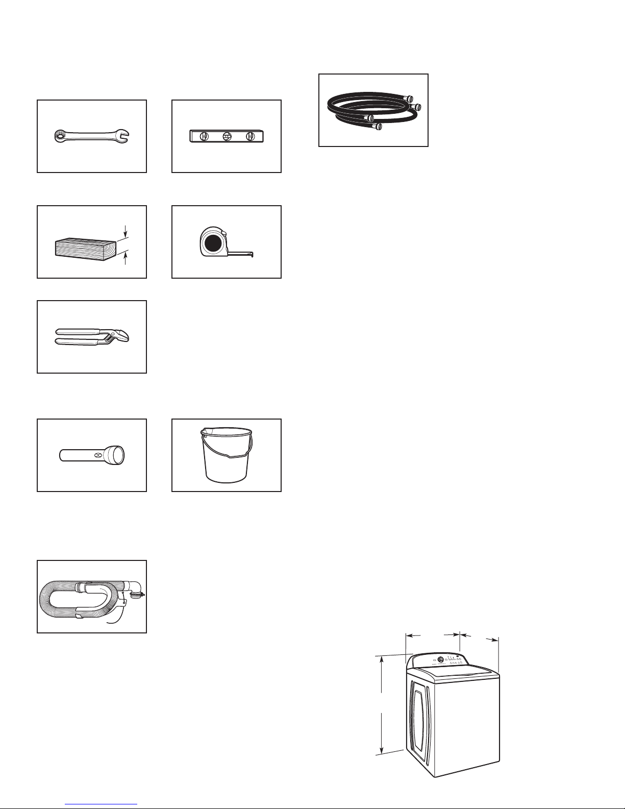
Tools and Parts
Gather required tools and parts before starting installation.
Tools needed:
Adjustable or open end
wrench 9/16" (14 mm)
4" min
(102 mm)
Wood block
Pliers that open to
13⁄4" (44.5 mm)
Level
Ruler or measuring tape
Optional tools:
Flashlight Bucket
Parts supplied:
NOTE: All parts supplied for installation are in
cardboard insert in the top of the washer.
Parts needed: (Not supplied with washer)
Inlet hoses with
flat washers
To order, please refer to toll-free phone numbers on back page
of your Use and Care Guide.
n
8212656RP 10 ft. (3.0 m) Inlet hose, Black EPDM (2 pack)
n
8212641RP 5 ft. (1.5 m) Inlet hose, Black EPDM (2 pack)
n
8212646RP 4 ft. (1.2 m) Inlet hose, Black EPDM (2 pack)
n
8212545RP 5 ft. (1.5 m) Inlet hose, Red and Blue EPDM
(2 pack)
n
8212487RP 5 ft. (1.5 m) Nylon braided inlet hose (2 pack)
n
8212638RP 6 ft. (1.8 m) Nylon braided inlet hose, space
saving 90° elbow, hypro-blue steel couplings
(2 pack)
n
8212637RP 6 ft. (1.8 m) Inlet hose, Black EPDM, space
saving 90° elbow, hypro-blue steel couplings
(2 pack)
Alternate parts: (Not supplied with washer)
Your installation may require additional parts. To order, please
refer to toll-free numbers on back page of your Use and Care
Guide.
If you have: You will need:
Overhead sewer Standard 20 gal. (76 L) 39" (990 mm)
tall drain tub or utility sink, sump
pump and connectors (available from
local plumbing suppliers)
1" (25 mm) standpipe 2" (51 mm) diameter to 1" (25 mm)
diameter Standpipe Adapter
Part Number 3363920
Connector Kit Part Number 285835
Drain hose too short Extension Drain Hose Part
Number 285863
Connector Kit Part Number 285835
Lint clogged drain Drain Protector Part Number 367031
Connector Kit Part Number 285835
Drain hose with clamp,
U-form, and cable tie
2
LOCATION REQUIREMENTS
Select proper location for your washer to improve performance
and minimize noise and possible “washer walk”. Install your
washer in a basement, laundry room, closet, or recessed area.
1
/2"
42"
(1067 mm)
27
(699 mm)
27"
(686 mm)

You will need:
3"
4.5"
(114 mm)
n
A water heater set to 120° F (49° C).
n
A grounded electrical outlet located within 4 ft (1.2 m) of
power cord on back of washer.
n
Hot and cold water faucets located within 3 ft (0.9 m) of hot
and cold water ll valves on washer, and water pressure
of 20-100 psi (138-690 kPa).
n
A level oor with maximum slope of 1" (25 mm) under entire
washer. Installing on carpet is not recommended.
n
Floor must support washer’s total weight (with water and load)
of 315 lbs (143 kgs).
IMPORTANT: Do not install, store, or operate washer where it will
be exposed to weather or in temperatures below 32° F (0° C).
Water remaining in washer after use may cause damage in low
temperatures. See “Washer Care” in your Use and Care Guide
for winterizing information.
Proper installation is your responsibility.
Recessed area or closet installation
(76 mm)
14" max.
(356 mm)
17"
(432 mm)
2
48 in.
(310 cm2)
DRAIN SYSTEM
Drain system can be installed using a oor drain, wall standpipe,
oor standpipe, or laundry tub. Select method you need.
Floor standpipe drain system
39"
4.5"
(114 mm)
Minimum diameter for a standpipe drain: 2" (51 mm). Minimum
carry-away capacity: 17 gal. (64 L) per minute. Top of standpipe
must be at least 39" (990 mm) high; install no higher than
96" (2.44 m) from bottom of washer. If you must install higher
than 96" (2.44 m), you will need a sump pump system.
Wall standpipe drain system
4.5"
(114 mm)
See requirements for oor standpipe drain system.
Floor drain system
(990 mm)
2
24 in.
5"
(126 mm)
1"
(25 mm)
1"
(25 mm)
(155 cm2)
3"
(76 mm)
Dimensions show recommended spacing allowed, except for
closet door ventilation openings which are minimum required.
This washer has been tested for installation with spacing of
0" (0 mm) clearance on the sides. Consider allowing more space
for ease of installation and servicing, and spacing for companion
appliances and clearances for walls, doors, and oor moldings.
Add spacing of 1" (25 mm) on all sides of washer to reduce
noise transfer. If a closet door or louvered door is installed,
top and bottom air openings in door are required.
Floor drain system requires a Siphon Break Kit (Part Number
285834), 2 Connector Kits (Part Number 285835), and an
Extension Drain Hose (Part Number 285863) that may be
purchased separately. To order, please see toll-free phone
numbers in your Use and Care Guide. Minimum siphon break:
28" (710 mm) from bottom of washer. (Additional hoses may
be needed.)
Laundry tub drain system
39"
(990 mm)
Minimum capacity: 20 gal. (76 L). Top of laundry tub must be at
least 39" (990 mm) above oor; install no higher than 96" (2.44 m)
from bottom of washer.
IMPORTANT: To avoid siphoning, no more than 4.5" (114 mm)
of drain hose should be inside standpipe or below the top of
wash tub. Secure drain hose with cable tie.
3

ELECTRICAL REQUIREMENTS
n
A 120 volt, 60 Hz., AC only, 15- or 20-amp, fused electrical supply
is required. A time-delay fuse or circuit breaker is recommended.
It is recommended that a separate circuit breaker serving only this
appliance be provided.
n
This washer is equipped with a power supply cord having
a 3 prong grounding plug.
n
To minimize possible shock hazard, the cord must be plugged
into a mating, 3 prong, grounding-type outlet, grounded in
accordance with local codes and ordinances. If a mating outlet
is not available, it is the personal responsibility and obligation
of the customer to have the properly grounded outlet installed
by a qualied electrician.
n
If codes permit and a separate ground wire is used, it is
recommended that a qualied electrician determine that
the ground path is adequate.
n
Do not ground to a gas pipe.
n
Check with a qualied electrician if you are not sure the
washer is properly grounded.
n
Do not have a fuse in the neutral or ground circuit.
INSTALLATION INSTRUCTIONS
Before you start: remove shipping materials
It is necessary to remove all shipping materials for proper
operation and to avoid excessive noise from washer.
1. Move washer
48"
(1.2 m)
Move washer to within 4 ft (1.2 m) of its nal location; it must
be in a fully upright position.
NOTE: To avoid oor damage, set washer onto cardboard
before moving it and make sure lid is taped shut.
2. Remove shipping base
4
To avoid damaging oor, place cardboard supports from
shipping carton on oor behind washer. Tip washer back and
place on cardboard supports. Remove shipping base. Set
washer upright.
IMPORTANT: Removing shipping base is necessary for proper
operation. If your washer includes a sound shield, please refer
to the instructions included with the sound shield to install it at
this time.

3. Remove packing tray from tub
Remove tape from washer lid, open lid and remove cardboard
packing tray from tub. Be sure to remove all parts from tray.
NOTE: Keep tray in case you need to move washer later.
4. Free power cord
CONNECT DRAIN HOSE
5. Attach drain hose to drain port
Remove the red plastic plug from the black drain port on the
back of the washer.
If clamp is not already in place on elbow end of drain hose,
slide it over end as shown. Squeeze clamp with pliers and
slide black elbow end of drain hose onto black drain port
and secure with clamp.
For a laundry tub or standpipe drain, go to step 6.
For a oor drain, remove the preinstalled drain hose form as
shown in Step 7. You may need additional parts with separate
directions. See “Tools and Parts”.
Firmly grasp power cord plug and pull to free from rear panel.
Gently place power cord over console to allow free access
to back of washer.
6. Place drain hose in standpipe
Drain
hose form
4.5"
(114 mm)
Place hose into standpipe (shown in picture) or over side of
laundry tub.
IMPORTANT: 4.5" (114 mm) of drain hose should be inside
standpipe; do not force excess hose into standpipe or lay on
bottom of laundry tub. Drain hose form must be used.
5
 Loading...