


 Loading...
Cyclone V SoC Development Kit
User Guide
101 Innovation Drive San Jose, CA 95134 www.altera.com
UG-01135-1.1
Feedback Subscribe

© 2013 Altera Corporation. All rights reserved. ALTERA, ARRIA, CYCLONE, HARDCOPY, MAX, MEGACORE, NIOS, QUARTUS and STRATIX words and logos |
|
|
are trademarks of Altera Corporation and registered in the U.S. Patent and Trademark Office and in other countries. All other words and logos identified as |
ISO |
|
trademarks or service marks are the property of their respective holders as described at www.altera.com/common/legal.html. Altera warrants performance of its |
||
semiconductor products to current specifications in accordance with Altera's standard warranty, but reserves the right to make changes to any products and |
9001:2008 |
|
services at any time without notice. Altera assumes no responsibility or liability arising out of the application or use of any information, product, or service |
Registered |
|
described herein except as expressly agreed to in writing by Altera. Altera customers are advised to obtain the latest version of device specifications before relying |
|
|
on any published information and before placing orders for products or services. |
|
|
November 2013 Altera Corporation |
Cyclone V SoC Development Kit |
|
|
|
User Guide |

Contents
Chapter 1. About This Kit
Kit Features . . . . . . . . . . . . . . . . . . . . . . . . . . . . . . . . . . . . . . . . . . . . . . . . . . . . . . . . . . . . . . . . . . . . . . . . . . . . 1–1
Before You Begin . . . . . . . . . . . . . . . . . . . . . . . . . . . . . . . . . . . . . . . . . . . . . . . . . . . . . . . . . . . . . . . . . . . . . . . . 1–1
Inspect the Boards . . . . . . . . . . . . . . . . . . . . . . . . . . . . . . . . . . . . . . . . . . . . . . . . . . . . . . . . . . . . . . . . . . . . 1–1
References . . . . . . . . . . . . . . . . . . . . . . . . . . . . . . . . . . . . . . . . . . . . . . . . . . . . . . . . . . . . . . . . . . . . . . . . . . . . . . 1–2
Chapter 2. Software Installation
Installing the Quartus II Web Edition Software . . . . . . . . . . . . . . . . . . . . . . . . . . . . . . . . . . . . . . . . . . . . . . 2–1
Licensing Considerations . . . . . . . . . . . . . . . . . . . . . . . . . . . . . . . . . . . . . . . . . . . . . . . . . . . . . . . . . . . . . . 2–1
Installing the Altera SoC EDS . . . . . . . . . . . . . . . . . . . . . . . . . . . . . . . . . . . . . . . . . . . . . . . . . . . . . . . . . . . . . 2–1
Installing the Development Kit . . . . . . . . . . . . . . . . . . . . . . . . . . . . . . . . . . . . . . . . . . . . . . . . . . . . . . . . . . . . 2–2
Installing the USB-Blaster II Driver . . . . . . . . . . . . . . . . . . . . . . . . . . . . . . . . . . . . . . . . . . . . . . . . . . . . . . . . 2–3
Chapter 3. Development Board Setup
Setting Up the Board . . . . . . . . . . . . . . . . . . . . . . . . . . . . . . . . . . . . . . . . . . . . . . . . . . . . . . . . . . . . . . . . . . . . . 3–1 Factory Default Switch and Jumper Settings . . . . . . . . . . . . . . . . . . . . . . . . . . . . . . . . . . . . . . . . . . . . . . . . 3–1 Restoring the MAX V CPLD to the Factory Settings . . . . . . . . . . . . . . . . . . . . . . . . . . . . . . . . . . . . . . . . . . 3–5 Restoring the CFI Flash Device to the Factory Defaults . . . . . . . . . . . . . . . . . . . . . . . . . . . . . . . . . . . . . . . 3–6
Chapter 4. Board Update Portal
Connecting to the Board Update Portal Web Page . . . . . . . . . . . . . . . . . . . . . . . . . . . . . . . . . . . . . . . . . . . |
4–1 |
Chapter 5. Board Test System
Preparing the Board for the Board Test System . . . . . . . . . . . . . . . . . . . . . . . . . . . . . . . . . . . . . . . . . . . . . . 5–2 Running the Board Test System . . . . . . . . . . . . . . . . . . . . . . . . . . . . . . . . . . . . . . . . . . . . . . . . . . . . . . . . . . . 5–2 Using the Board Test System . . . . . . . . . . . . . . . . . . . . . . . . . . . . . . . . . . . . . . . . . . . . . . . . . . . . . . . . . . . . . . 5–3 The Configure Menu . . . . . . . . . . . . . . . . . . . . . . . . . . . . . . . . . . . . . . . . . . . . . . . . . . . . . . . . . . . . . . . . . . 5–3 The System Info Tab . . . . . . . . . . . . . . . . . . . . . . . . . . . . . . . . . . . . . . . . . . . . . . . . . . . . . . . . . . . . . . . . . . . 5–3 Board Information . . . . . . . . . . . . . . . . . . . . . . . . . . . . . . . . . . . . . . . . . . . . . . . . . . . . . . . . . . . . . . . . . . 5–3 JTAG Chain . . . . . . . . . . . . . . . . . . . . . . . . . . . . . . . . . . . . . . . . . . . . . . . . . . . . . . . . . . . . . . . . . . . . . . . . 5–4 The GPIO Tab . . . . . . . . . . . . . . . . . . . . . . . . . . . . . . . . . . . . . . . . . . . . . . . . . . . . . . . . . . . . . . . . . . . . . . . . 5–5 Character LCD . . . . . . . . . . . . . . . . . . . . . . . . . . . . . . . . . . . . . . . . . . . . . . . . . . . . . . . . . . . . . . . . . . . . . 5–5 User DIP Switch . . . . . . . . . . . . . . . . . . . . . . . . . . . . . . . . . . . . . . . . . . . . . . . . . . . . . . . . . . . . . . . . . . . . 5–5 User LEDs . . . . . . . . . . . . . . . . . . . . . . . . . . . . . . . . . . . . . . . . . . . . . . . . . . . . . . . . . . . . . . . . . . . . . . . . . 5–6 Push Button Switches . . . . . . . . . . . . . . . . . . . . . . . . . . . . . . . . . . . . . . . . . . . . . . . . . . . . . . . . . . . . . . . 5–6 The I2C Tab . . . . . . . . . . . . . . . . . . . . . . . . . . . . . . . . . . . . . . . . . . . . . . . . . . . . . . . . . . . . . . . . . . . . . . . . . . 5–6 EEPROM . . . . . . . . . . . . . . . . . . . . . . . . . . . . . . . . . . . . . . . . . . . . . . . . . . . . . . . . . . . . . . . . . . . . . . . . . . 5–7 RTC . . . . . . . . . . . . . . . . . . . . . . . . . . . . . . . . . . . . . . . . . . . . . . . . . . . . . . . . . . . . . . . . . . . . . . . . . . . . . . 5–7 The DDR3 Tab . . . . . . . . . . . . . . . . . . . . . . . . . . . . . . . . . . . . . . . . . . . . . . . . . . . . . . . . . . . . . . . . . . . . . . . . 5–8 Start . . . . . . . . . . . . . . . . . . . . . . . . . . . . . . . . . . . . . . . . . . . . . . . . . . . . . . . . . . . . . . . . . . . . . . . . . . . . . . 5–8 Stop . . . . . . . . . . . . . . . . . . . . . . . . . . . . . . . . . . . . . . . . . . . . . . . . . . . . . . . . . . . . . . . . . . . . . . . . . . . . . . 5–8 Performance Indicators . . . . . . . . . . . . . . . . . . . . . . . . . . . . . . . . . . . . . . . . . . . . . . . . . . . . . . . . . . . . . . 5–8 Error Control . . . . . . . . . . . . . . . . . . . . . . . . . . . . . . . . . . . . . . . . . . . . . . . . . . . . . . . . . . . . . . . . . . . . . . 5–9 Number of Addresses to Write and Read . . . . . . . . . . . . . . . . . . . . . . . . . . . . . . . . . . . . . . . . . . . . . . 5–9 The SDI Video Tab . . . . . . . . . . . . . . . . . . . . . . . . . . . . . . . . . . . . . . . . . . . . . . . . . . . . . . . . . . . . . . . . . . . 5–10 Pattern Generator . . . . . . . . . . . . . . . . . . . . . . . . . . . . . . . . . . . . . . . . . . . . . . . . . . . . . . . . . . . . . . . . . . 5–11 The HSMC Tab . . . . . . . . . . . . . . . . . . . . . . . . . . . . . . . . . . . . . . . . . . . . . . . . . . . . . . . . . . . . . . . . . . . . . . 5–13 Start, Stop . . . . . . . . . . . . . . . . . . . . . . . . . . . . . . . . . . . . . . . . . . . . . . . . . . . . . . . . . . . . . . . . . . . . . . . . 5–13
November 2013 Altera Corporation |
Cyclone V SoC Development Kit |
|
User Guide |
iv |
Contents |
|
|
XCVR, LVDS, CMOS . . . . . . . . . . . . . . . . . . . . . . . . . . . . . . . . . . . . . . . . . . . . . . . . . . . . . . . . . . . . . . . 5–14 The Power Monitor . . . . . . . . . . . . . . . . . . . . . . . . . . . . . . . . . . . . . . . . . . . . . . . . . . . . . . . . . . . . . . . . . . . . . 5–15 U34 and U26 . . . . . . . . . . . . . . . . . . . . . . . . . . . . . . . . . . . . . . . . . . . . . . . . . . . . . . . . . . . . . . . . . . . . . . 5–16 Controls . . . . . . . . . . . . . . . . . . . . . . . . . . . . . . . . . . . . . . . . . . . . . . . . . . . . . . . . . . . . . . . . . . . . . . . . . . 5–16 The Clock Control . . . . . . . . . . . . . . . . . . . . . . . . . . . . . . . . . . . . . . . . . . . . . . . . . . . . . . . . . . . . . . . . . . . . . . 5–17 Serial Port Registers . . . . . . . . . . . . . . . . . . . . . . . . . . . . . . . . . . . . . . . . . . . . . . . . . . . . . . . . . . . . . . . . 5–18 fXTAL . . . . . . . . . . . . . . . . . . . . . . . . . . . . . . . . . . . . . . . . . . . . . . . . . . . . . . . . . . . . . . . . . . . . . . . . . . . 5–18 Target Frequency . . . . . . . . . . . . . . . . . . . . . . . . . . . . . . . . . . . . . . . . . . . . . . . . . . . . . . . . . . . . . . . . . . 5–18 Default . . . . . . . . . . . . . . . . . . . . . . . . . . . . . . . . . . . . . . . . . . . . . . . . . . . . . . . . . . . . . . . . . . . . . . . . . . . 5–18 Set New Frequency . . . . . . . . . . . . . . . . . . . . . . . . . . . . . . . . . . . . . . . . . . . . . . . . . . . . . . . . . . . . . . . . 5–19
Configuring the FPGA Using the Quartus II Programmer . . . . . . . . . . . . . . . . . . . . . . . . . . . . . . . . . . . . 5–19 Before Configuring . . . . . . . . . . . . . . . . . . . . . . . . . . . . . . . . . . . . . . . . . . . . . . . . . . . . . . . . . . . . . . . . . . . 5–19 Configuring the FPGA . . . . . . . . . . . . . . . . . . . . . . . . . . . . . . . . . . . . . . . . . . . . . . . . . . . . . . . . . . . . . . . . 5–19
Appendix A. Programming Flash Memory
CFI Flash Memory . . . . . . . . . . . . . . . . . . . . . . . . . . . . . . . . . . . . . . . . . . . . . . . . . . . . . . . . . . . . . . . . . . . . . . A–1 CFI Flash Memory Map . . . . . . . . . . . . . . . . . . . . . . . . . . . . . . . . . . . . . . . . . . . . . . . . . . . . . . . . . . . . . . . A–1 Programming CFI Flash Using the Quartus II Programmer . . . . . . . . . . . . . . . . . . . . . . . . . . . . . . . . A–1 Converting .sof Files to a .pof . . . . . . . . . . . . . . . . . . . . . . . . . . . . . . . . . . . . . . . . . . . . . . . . . . . . . . . . . . A–3 quad SPI Flash Memory . . . . . . . . . . . . . . . . . . . . . . . . . . . . . . . . . . . . . . . . . . . . . . . . . . . . . . . . . . . . . . . . . A–3 Programming quad SPI Flash Using the Quartus II Programmer . . . . . . . . . . . . . . . . . . . . . . . . . . . A–3 SD Card Memory . . . . . . . . . . . . . . . . . . . . . . . . . . . . . . . . . . . . . . . . . . . . . . . . . . . . . . . . . . . . . . . . . . . . . . . A–4 Programming the SD Card Boot Image . . . . . . . . . . . . . . . . . . . . . . . . . . . . . . . . . . . . . . . . . . . . . . . . . . A–4
Additional Information
Document Revision History . . . . . . . . . . . . . . . . . . . . . . . . . . . . . . . . . . . . . . . . . . . . . . . . . . . . . . . . . . . |
Info–1 |
How to Contact Altera . . . . . . . . . . . . . . . . . . . . . . . . . . . . . . . . . . . . . . . . . . . . . . . . . . . . . . . . . . . . . . . . |
Info–1 |
Typographic Conventions . . . . . . . . . . . . . . . . . . . . . . . . . . . . . . . . . . . . . . . . . . . . . . . . . . . . . . . . . . . . . |
Info–1 |
Cyclone V SoC Development Kit |
November 2013 Altera Corporation |
User Guide |
|

1. About This Kit
The Altera® Cyclone® V system on a chip (SoC) Development Kit is a complete design environment that includes both the hardware and software you need to develop Cyclone V SoC designs.
Kit Features
This section briefly describes the kit contents.
fFor a complete list of this kit’s contents and capabilities, refer to the Cyclone V SoC Development Kit page.
The Cyclone V SoC Development Kit includes the following hardware:
■Cyclone V development board—A development platform that allows you to develop and prototype hardware designs running on the Cyclone V SoC.
f For detailed information about the board components and interfaces, refer to the Cyclone V SoC Development Board Reference Manual.
■microSD flash memory card.
■Debug header breakout board high-speed mezzanine card (HSMC).
■Loopback daughtercard HSMC.
■Power supply and cables—The kit includes the following items:
■Power supply and AC adapters for North America/Japan, Europe, and the United Kingdom.
■USB cable.
■Ethernet cable.
■SMB cable.
Before You Begin
Before using the kit or installing the software, check the kit contents and inspect the boards to verify that you received all of the items listed in Quick Start Guide printout in the box. If any of the items are missing, contact Altera before you proceed.
Inspect the Boards
To inspect each board, perform these steps:
1.Place the board on an anti-static surface and inspect it to ensure that it has not been damaged during shipment.
c Without proper anti-static handling, you can damage the board.
November 2013 Altera Corporation |
Cyclone V SoC Development Kit |
|
User Guide |
1–2 |
Chapter 1: About This Kit |
|
References |
|
|
2. Verify that all components on the boards appear in place and intact.
1In typical applications with the Cyclone V development board, a heat sink is not necessary. However, under extreme conditions or for engineering sample silicon, the board might require additional cooling to stay within operating temperature guidelines. The board has two holes near the FPGA that accommodate many different heat sinks, including the Dynatron V31G. You can perform power consumption and thermal modeling to determine whether your application requires additional cooling. For information about measuring board and FPGA power in real time, refer to “The Power Monitor” on page 5–15.
fFor more information about power consumption and thermal modeling, refer to AN 358: Thermal Management for FPGAs.
References
Use the following links in Table 1–1 to check the Altera website for other related information:
Table 1–1. Related Links and Documents
Altera Website Link |
Information |
|
|
|
|
Cyclone V SoC Development Kit page |
Latest board design files, reference designs, kit |
|
installation for Windows and Linux. |
||
|
||
|
|
|
|
Open-source community website supporting SoC |
|
RocketBoards.org |
development including Altera and Partner SoC |
|
development kit targets and related designs and |
||
|
||
|
documentation. |
|
|
|
|
ARM Cortex-A (SoC) |
On the dual-core ARM Cortex-A9 MPCore processor. |
|
|
|
|
Getting Started for Software Developers |
Developing software for the Cyclone V SoC. |
|
|
|
|
Cyclone V SoC Development Kit Hardware |
Developing SoC Hardware designs on the |
|
Developer Resource Center |
development kit. |
|
|
|
|
Altera SoC Embedded Design Suite User |
Installing the SoC EDS and ARM DS-5. Preloader |
|
user guide. Hard Processor System (HPS) Flash |
||
Guide |
programmer. Bare Metal and Linux Compiler. Yocto |
|
|
plugin. Debugging. |
|
|
|
|
|
The Golden System Reference Design (GSRD) |
|
GSRD User Manual page |
demonstrates the HPS features and the ability to |
|
communicate between HPS to the FPGA logic via the |
||
|
||
|
AXI Bridge interfaces. |
|
|
|
|
Cyclone V SoC Development Board |
Complete information about the development board. |
|
Reference Manual |
||
|
||
|
|
|
Development Board Daughtercards |
Additional daughter cards available for purchase. |
|
|
|
|
Documentation: Cyclone V Devices |
Cyclone V device documentation. |
|
|
|
|
Devices |
Purchase devices from the eStore. |
|
|
|
|
Capture CIS Symbols |
Cyclone V OrCAD symbols. |
|
|
|
|
Embedded Processing |
Nios II 32-bit embedded processor solutions. |
|
|
|
Cyclone V SoC Development Kit |
November 2013 Altera Corporation |
User Guide |
|

2. Software Installation
This chapter explains how to install the following software:
■Quartus II Web Edition Software (optional)
■Altera SoC Embedded Development Suite (EDS)
■Cyclone V SoC Development Kit software
■On-Board USB-Blaster™ II driver
1If you do not need to develop FPGA designs, you do not need to download the Quartus II software. For example, when you only want to write software for the SoC HPS. Installing the SoC EDS software, along with USB-II Blaster drivers, can provide your development kit JTAG programming environment.
Installing the Quartus II Web Edition Software
Perform these steps:
1.Download the Quartus II Web Edition Software from the Quartus II Subscription Edition Software page of the Altera website.
Alternatively, you can request a DVD from the Altera IP and Software DVD Request Form page of the Altera website.
2.Run the Quartus II Web Edition Software installer.
3.Follow the on-screen instructions to complete the installation process.
fFor a list of the Web Edition capabilities and features, refer to the Detailed Comparison sheet.
fIf you have difficulty installing the Quartus II software, refer to the Altera Software Installation and Licensing Manual.
Licensing Considerations
The Quartus II Web Edition Software is license-free and supports Cyclone V devices without any additional licensing requirement. This kit also works in conjunction with the Quartus II Subscription Edition Software, once you obtain the proper license file. To purchase a subscription, contact your Altera sales representative.
Installing the Altera SoC EDS
The Altera SoC EDS is a comprehensive tool suite for embedded software development on Altera SoC devices. The Altera SoC EDS contains the following:
■Development tools
■Utility programs
■Run-time software
November 2013 Altera Corporation |
Cyclone V SoC Development Kit |
|
User Guide |

2–2 |
Chapter 2: Software Installation |
|
Installing the Development Kit |
|
|
■ Application examples that enable firmware and application software development
The SoC EDS includes an exclusive offering of the ARM Development Studio™ 5 (DS-5™) Altera Edition Toolkit. The ARM DS-5 combines advanced multicore debugging capabilities with FPGA adaptivity. With Altera’s SignalTap™ II Logic Analyzer, embedded software developers have full-chip visibility and control.
fFor the steps to install the SoC EDS Design Suite, refer to the Altera SoC Embedded Design Suite User Guide.
Installing the Development Kit
Perform these steps:
1.Download the Cyclone V SoC Development Kit installer from the Cyclone V SoC Development Kit page of the Altera website. Alternatively, you can request a development kit DVD from the Altera Kit Installations DVD Request Form page of the Altera website.
2.Start the Cyclone V SoC Development Kit installer.
3.Choose an installation directory that is relative to the Quartus II software installation directory. Follow the on-screen instructions to complete the installation process.
4.For the latest issues and release notes, Altera recommends that you review the readme.txt located in the root directory of the kit installation.
The installation program creates the Cyclone V SoC Development Kit directory structure shown in Figure 2–1.
Figure 2–1. Cyclone V SoC Development Kit Installed Directory Structure (1)
 <install dir>
The default Windows installation directory is C:\altera\<version>\.
kits
 cycloneVSX_5csxfc6df31_soc
 board_design_files
 demos
demos  documents
examples
 factory_recovery
Note to Figure 2–1:
(1) Early-release versions might have slightly different directory names.
Cyclone V SoC Development Kit |
November 2013 Altera Corporation |
User Guide |
|

Chapter 2: Software Installation |
2–3 |
Installing the USB-Blaster II Driver
Table 2–1 lists the file directory names and a description of their contents.
Table 2–1. Installed Directory Contents
Directory Name |
Description of Contents |
|
|
|
|
board_design_files |
Contains schematic, layout, assembly, and bill of material board design files. Use these files as a |
|
starting point for a new prototype board design. |
||
|
||
|
|
|
demos |
Contains demonstration applications, if available. |
|
|
|
|
documents |
Contains the kit documentation. |
|
|
|
|
examples |
Contains the sample design files for the Cyclone V SoC Development Kit. |
|
|
|
|
factory_recovery |
Contains the original data programmed onto the board before shipment. Use this data to restore |
|
the board with its original factory contents. |
||
|
||
|
|
Installing the USB-Blaster II Driver
The Cyclone V development board includes integrated USB-Blaster circuitry for FPGA programming. However, for the host computer and board to communicate, you must install the On-Board USB-Blaster II driver on the host computer.
fInstallation instructions for the On-Board USB-Blaster II driver for your operating system are available on the Altera website. On the Altera Programming Cable Driver Information page of the Altera website, locate the table entry for your configuration and click the link to access the instructions.
f For USB-Blaster II configuration details, refer to the On-Board USB-Blaster II page.
November 2013 Altera Corporation |
Cyclone V SoC Development Kit |
|
User Guide |
2–4 |
Chapter 2: Software Installation |
|
Installing the USB-Blaster II Driver |
|
|
Cyclone V SoC Development Kit |
November 2013 Altera Corporation |
User Guide |
|
3. Development Board Setup
This chapter explains how to set up the Cyclone V SoC development board and restore default settings.
Setting Up the Board
To prepare the board, perform these steps:
1.The development board ships with its board switches preconfigured to support the design examples in the kit. If you suspect your board might not be currently configured with the default settings, follow the instructions in “Factory Default Switch and Jumper Settings” on page 3–1 to return the board to its factory settings before proceeding.
The development board ships with the Golden System Reference Design binaries stored in the microSD card.
The microSD card also includes the following:
■Hardware reference design FPGA image, Raw Binary File (.rbf) file
■HPS image preloader U-Boot and Linux images
■File system and software examples
2.Power up the development board by using the included laptop power supply plugged into J22 on the board.
c Use only the supplied power supply. Power regulation circuitry on the board can be damaged by power supplies with greater voltage, and a lower-rated power supply may not be able to provide enough power for the board.
Alternatively, you can use the an ATX power from a PC by plugging a 4-pin output from that supply to J20 on the development board.
c Make sure that the ATX supply is off when connecting to the board. Hotswap is not supported and may damage the board's power supplies and other downstream devices.
When configuration is complete, the Config Done LED (D38) illuminates, signaling that the Cyclone V device configured successfully.
Factory Default Switch and Jumper Settings
This section shows the factory settings (Figure 3–1) for the Cyclone V SoC development board. These settings ensure that the Board Update Portal and Golden System Reference design function properly.
November 2013 Altera Corporation |
Cyclone V SoC Development Kit |
|
User Guide |
3–2 |
Chapter 3: Development Board Setup |
|
Factory Default Switch and Jumper Settings |
|
|
1The SD card, Max V system controller, and common flash interface (CFI) flash are already programmed with the factory default files. For more information, refer to Appendix A, Programming Flash Memory.
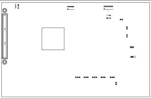
Figure 3–1. Switch Locations and Default Settings
SW2
|
|
4 |
|
|
|
|
|
|
|
3 |
|
|
|
|
|
2 |
|
|
|
|
ON |
1 |
|
|
|
|
SECURITY FACT LOAD Si570 CLK125A
0 1 2 3 4 |
|
|
SW1 |
|
3 2 1 0 |
|
|
|
|||||||||||||
|
ON |
|
|
|
|
|
|
8 |
7 |
6 |
|
5 |
34 |
2 |
1 |
|
|
|
|||
SW3 |
|
|
|
|
|
|
|
|
|
|
|
|
|
|
|
|
|
|
|
|
|
|
1 |
2 |
3 |
4 |
5 |
6 |
|
|
|
|
|
|
|
|
|
|
ON |
|
|
|
|
|
|
|
MSEL |
|
|
FPGA |
|
|
|
|
HPS |
|
|
||||||||
|
|
|
|
|
|
ENABLE |
|
|
|
|
|
|
|
SW4 |
|
|
|||||
|
|
|
|
|
|
|
|
|
|
|
|
|
|
|
|
|
|
|
|||
|
|
|
|
|
|
|
|
|
|
|
ON |
|
|
|
|
|
|
||||
|
|
|
|
|
|
|
|
|
|
|
|
|
|
|
|
|
|
9V |
|
|
|
|
|
|
|
|
|
|
|
|
|
|
|
1 |
2 |
3 |
4 |
|
|
|
|
|
|
|
|
|
|
|
|
|
|
|
|
JTAG |
|
HPS |
FPGA HSMC |
MAX |
|
J5 |
|
|
|||
|
|
|
|
|
|
|
|
|
|
|
|
|
|
|
|
|
|
|
|
|
|
|
|
|
|
|
|
|
|
|
|
|
|
|
|
|
|
|
|
|
JTAG |
|
J6 |
|
|
|
|
|
|
|
|
|
|
|
|
|
|
|
|
|
|
|
|||
|
|
|
|
|
|
|
|
|
|
|
|
|
|
|
|
|
|
|
HPS SEL |
|
J7 |
|
|
|
|
|
|
|
|
|
|
|
|
|
|
|
|
|
|
|
|||
|
|
|
|
|
|
|
|
|
|
|
|
|
|
|
|
|
|
|
JTAG |
|
|
|
|
|
|
|
|
|
|
|
|
|
|
|
|
|
|
|
|
|
|||
|
|
|
|
|
|
|
|
|
|
|
|
|
|
|
|
|
|
|
SEL |
|
|
|
|
|
|
|
|
|
|
|
|
|
|
|
|
|
|
|
|
|
|
||
OSC1_CLK_SEL
J13
JTAG_MIC_SEL
J16
J26 |
J27 |
|
J28 |
J29 |
|
J30 |
||||||||||
|
|
|
|
|
|
|
|
|
|
|
|
|
|
|
|
|
CLKSEL0 |
CLKSEL1 |
BOOTSEL0 |
BOOTSEL1 |
BOOTSEL2 |
|
SPI |
||||||||||
|
|
|
|
|
|
|
|
|
|
|
|
|
|
|
|
I2C |
|
|
|
|
|
|
|
|
|
|
|
|
|
|
J31 |
||
To restore the switches to their factory default settings, perform these steps:
1.Set the DIP switch bank (SW2) to match Table 3–1 and Figure 3–1.
In the following table, ON indicates the switch is to the left according to the board orientation as shown in Figure 3–1.
Table 3–1. SW2 DIP Switch Settings (Part 1 of 2)
Switch |
Board |
Function |
Default |
|
Label |
Position |
|||
|
|
|||
|
|
|
|
|
|
|
Switch 1 has the following options: |
|
|
1 |
CLK125A |
■ ON (0) = On-board oscillator is disabled. |
OFF |
|
|
|
■ OFF (1) = On-board oscillator is enabled. |
|
|
|
|
|
|
|
|
|
Switch 2 has the following options: |
|
|
|
|
■ ON (0) = On-board programmable oscillator is |
|
|
2 |
Si570 |
enabled. |
ON |
|
|
|
■ OFF (1) = On-board programmable oscillator is |
|
|
|
|
disabled. |
|
|
|
|
|
|
Cyclone V SoC Development Kit |
November 2013 Altera Corporation |
User Guide |
|
Chapter 3: Development Board Setup |
3–3 |
Factory Default Switch and Jumper Settings |
|
|
|
Table 3–1. SW2 DIP Switch Settings (Part 2 of 2)
Switch |
Board |
Function |
Default |
|
Label |
Position |
|||
|
|
|||
|
|
|
|
|
|
|
Switch 3 has the following options: |
|
|
3 |
FACT LOAD |
■ ON (0) = Load the factory design starting at |
OFF |
|
0x20000 at power up. |
||||
|
|
|
||
|
|
■ OFF (1) = Parallel flash loader (PFL) disabled. |
|
|
|
|
|
|
|
|
|
Switch 4 has the following options: |
|
|
4 |
Security |
■ ON (0) = On-Board USB Blaster II sends |
|
|
FACTORY command at power up |
OFF |
|||
|
|
■ OFF (1) = On-Board USB Blaster II does not |
|
|
|
|
send FACTORY command at power up |
|
|
|
|
|
|
2.Set the DIP switch bank (SW3) to match Table 3–2 and Figure 3–1.
In the following table, up and down indicates the position of the switch with the board orientation as shown in Figure 3–1.
Important: The default MSEL pin settings are set to all zeroes (ON) to select the fast passive parallel x16 mode. For power-up configuration from MAX V and CFI flash, ensure that the MAX V design uses this same mode as does in the design in the <install dir>\kits\cycloneVSX_5csxfc6df31_soc\examples\max5 directory.
Table 3–2. SW3 DIP Switch Settings
Switch |
Board |
Function |
Default |
|
Label |
Position |
|||
|
|
|||
|
|
|
|
|
|
|
Switch 1 has the following options: |
|
|
1 |
MSEL0 |
■ ON (up) = MSEL0 is 0. |
ON |
|
|
|
■ OFF (down) = MSEL0 is 1. |
|
|
|
|
|
|
|
|
|
Switch 2 has the following options: |
|
|
2 |
MSEL1 |
■ ON (up) = MSEL1 is 0. |
ON |
|
|
|
■ OFF (down) = MSEL1 is 1. |
|
|
|
|
|
|
|
|
|
Switch 3 has the following options: |
|
|
3 |
MSEL2 |
■ ON (up) = MSEL2 is 0. |
ON |
|
|
|
■ OFF (down) = MSEL2 is 1. |
|
|
|
|
|
|
|
|
|
Switch 4 has the following options: |
|
|
4 |
MSEL3 |
■ ON (up) = MSEL3 is 0. |
ON |
|
|
|
■ OFF (down) = MSEL3 is 1. |
|
|
|
|
|
|
|
|
|
Switch 5 has the following options: |
|
|
5 |
MSEL4 |
■ ON (up) = MSEL4 is 0. |
ON |
|
|
|
■ OFF (down) = MSEL4 is 1. |
|
|
|
|
|
|
November 2013 Altera Corporation |
Cyclone V SoC Development Kit |
|
User Guide |
3–4 |
Chapter 3: Development Board Setup |
|
Factory Default Switch and Jumper Settings |
|
|
3.Set the DIP switch bank (SW4) to match Table 3–3 and Figure 3–1.
In the following table, up and down indicates the position of the switch with the board orientation as shown in Figure 3–1.
Table 3–3. SW4 JTAG DIP Switch Settings
Switch |
Board |
Function |
Default |
|
Label |
Position |
|||
|
|
|||
|
|
|
|
|
1 |
HPS |
■ ON (up) = Do not Include HPS in the JTAG chain. |
OFF |
|
■ OFF (down) = Include HPS in the JTAG chain |
||||
|
|
|
||
|
|
|
|
|
|
|
■ ON (up) = Do not Include the FPGA in the JTAG |
|
|
2 |
FPGA |
chain. |
OFF |
|
|
|
■ OFF (down) = Include the FPGA in the JTAG chain. |
|
|
|
|
|
|
|
|
|
■ ON (up) = Do not include the HSMC connector in the |
|
|
3 |
HSMC |
JTAG chain. |
ON |
|
■ OFF (down) = Include the HSMC connector in the |
||||
|
|
|
||
|
|
JTAG chain. |
|
|
|
|
|
|
|
|
|
■ ON (up) = Do not include the MAX V system |
|
|
4 |
MAX |
controller in the JTAG chain. |
OFF |
|
■ OFF (down) = Include the MAX V system controller in |
||||
|
|
|
||
|
|
the JTAG chain. |
|
|
|
|
|
|
4. Set the following jumper blocks to match Table 3–4 and Figure 3–1.
Table 3–4. Default Jumper Settings
Board |
Board Label |
|
Description |
Default |
|
Reference |
|
Position |
|||
|
|
|
|||
|
|
|
|
||
|
|
■ SHORT: Powers the CFI flash memory device |
|
||
|
|
|
using a 9 V supply for fast write in |
|
|
J5 |
9V |
|
manufacturing. |
OPEN |
|
|
|
■ OPEN: Powers CFI flash memory from the |
|
||
|
|
|
default 3 V supply. |
|
|
|
|
|
|
||
|
|
■ SHORT: Controls the HPS from On-Board USB |
|
||
|
|
|
Blaster II JTAG master. |
|
|
J6 |
JTAG HPS SEL |
■ OPEN: Controls the HPS from MICTOR-based |
SHORT |
||
|
JTAG master, such as DSTREAM or Lauterbach |
||||
|
|
|
programming cables. Also, set SW4.1 to ON to |
|
|
|
|
|
remove the On-Board USB Blaster II from |
|
|
|
|
|
driving the HPS JTAG input port in this mode. |
|
|
|
|
|
|
||
|
|
■ SHORT: The USB Blaster II is the source of the |
|
||
J7 |
JTAG SEL |
|
JTAG chain. |
SHORT |
|
■ OPEN: The Mictor is the source of the JTAG |
|||||
|
|
|
|||
|
|
|
chain. |
|
|
|
|
|
|
||
J13 |
OSC1_CLK_SEL |
■ SHORT: Selects the on board 25MHz clock. |
SHORT |
||
|
OPEN: Selects SMA. |
||||
|
|
■ |
|
||
|
|
|
|
|
|
Cyclone V SoC Development Kit |
November 2013 Altera Corporation |
User Guide |
|
Loading...