


 Loading...
Cyclone V GX FPGA Development Kit
User Guide
101 Innovation Drive San Jose, CA 95134 www.altera.com
UG-01123-1.1
Feedback Subscribe

© 2012 Altera Corporation. All rights reserved. ALTERA, ARRIA, CYCLONE, HARDCOPY, MAX, MEGACORE, NIOS, QUARTUS and STRATIX words and logos |
|
|
are trademarks of Altera Corporation and registered in the U.S. Patent and Trademark Office and in other countries. All other words and logos identified as |
ISO |
|
trademarks or service marks are the property of their respective holders as described at www.altera.com/common/legal.html. Altera warrants performance of its |
||
semiconductor products to current specifications in accordance with Altera's standard warranty, but reserves the right to make changes to any products and |
9001:2008 |
|
services at any time without notice. Altera assumes no responsibility or liability arising out of the application or use of any information, product, or service |
Registered |
|
described herein except as expressly agreed to in writing by Altera. Altera customers are advised to obtain the latest version of device specifications before relying |
|
|
on any published information and before placing orders for products or services. |
|
|
October 2012 Altera Corporation |
Cyclone V GX FPGA Development Kit |
|
|
|
User Guide |

Contents
Chapter 1. About This Kit
Kit Features . . . . . . . . . . . . . . . . . . . . . . . . . . . . . . . . . . . . . . . . . . . . . . . . . . . . . . . . . . . . . . . . . . . . . . . . . . . . 1–1
Hardware . . . . . . . . . . . . . . . . . . . . . . . . . . . . . . . . . . . . . . . . . . . . . . . . . . . . . . . . . . . . . . . . . . . . . . . . . . . . 1–1
Software . . . . . . . . . . . . . . . . . . . . . . . . . . . . . . . . . . . . . . . . . . . . . . . . . . . . . . . . . . . . . . . . . . . . . . . . . . . . . 1–1
Quartus II Web Edition Software . . . . . . . . . . . . . . . . . . . . . . . . . . . . . . . . . . . . . . . . . . . . . . . . . . . . . 1–1
Cyclone V GX FPGA Development Kit Installer . . . . . . . . . . . . . . . . . . . . . . . . . . . . . . . . . . . . . . . . . 1–2
Chapter 2. Getting Started
Before You Begin . . . . . . . . . . . . . . . . . . . . . . . . . . . . . . . . . . . . . . . . . . . . . . . . . . . . . . . . . . . . . . . . . . . . . . . . 2–1
Inspect the Boards . . . . . . . . . . . . . . . . . . . . . . . . . . . . . . . . . . . . . . . . . . . . . . . . . . . . . . . . . . . . . . . . . . . . 2–1
References . . . . . . . . . . . . . . . . . . . . . . . . . . . . . . . . . . . . . . . . . . . . . . . . . . . . . . . . . . . . . . . . . . . . . . . . . . . . . . 2–2
Chapter 3. Software Installation
Installing the Quartus II Web Edition Software . . . . . . . . . . . . . . . . . . . . . . . . . . . . . . . . . . . . . . . . . . . . . . 3–1
Licensing Considerations . . . . . . . . . . . . . . . . . . . . . . . . . . . . . . . . . . . . . . . . . . . . . . . . . . . . . . . . . . . . . . 3–1
Installing the Development Kit . . . . . . . . . . . . . . . . . . . . . . . . . . . . . . . . . . . . . . . . . . . . . . . . . . . . . . . . . . . . 3–1
Installing the USB-Blaster II Driver . . . . . . . . . . . . . . . . . . . . . . . . . . . . . . . . . . . . . . . . . . . . . . . . . . . . . . . . 3–2
Chapter 4. Development Board Setup
Setting Up the Board . . . . . . . . . . . . . . . . . . . . . . . . . . . . . . . . . . . . . . . . . . . . . . . . . . . . . . . . . . . . . . . . . . . . . 4–1
Factory Default Switch Settings . . . . . . . . . . . . . . . . . . . . . . . . . . . . . . . . . . . . . . . . . . . . . . . . . . . . . . . . . . . 4–2
Chapter 5. Board Update Portal
Connecting to the Board Update Portal Web Page . . . . . . . . . . . . . . . . . . . . . . . . . . . . . . . . . . . . . . . . . . . |
5–1 |
Using the Board Update Portal to Update User Designs . . . . . . . . . . . . . . . . . . . . . . . . . . . . . . . . . . . . . . |
5–2 |
Chapter 6. Board Test System
Preparing the Board . . . . . . . . . . . . . . . . . . . . . . . . . . . . . . . . . . . . . . . . . . . . . . . . . . . . . . . . . . . . . . . . . . . . . 6–2
Running the Board Test System . . . . . . . . . . . . . . . . . . . . . . . . . . . . . . . . . . . . . . . . . . . . . . . . . . . . . . . . . . . 6–2
Using the Board Test System . . . . . . . . . . . . . . . . . . . . . . . . . . . . . . . . . . . . . . . . . . . . . . . . . . . . . . . . . . . . . . 6–3
The System Info Tab . . . . . . . . . . . . . . . . . . . . . . . . . . . . . . . . . . . . . . . . . . . . . . . . . . . . . . . . . . . . . . . . . . . 6–3
Board Information . . . . . . . . . . . . . . . . . . . . . . . . . . . . . . . . . . . . . . . . . . . . . . . . . . . . . . . . . . . . . . . . . . 6–3
MAX V Registers . . . . . . . . . . . . . . . . . . . . . . . . . . . . . . . . . . . . . . . . . . . . . . . . . . . . . . . . . . . . . . . . . . . 6–4
JTAG Chain . . . . . . . . . . . . . . . . . . . . . . . . . . . . . . . . . . . . . . . . . . . . . . . . . . . . . . . . . . . . . . . . . . . . . . . . 6–4
Qsys Memory Map . . . . . . . . . . . . . . . . . . . . . . . . . . . . . . . . . . . . . . . . . . . . . . . . . . . . . . . . . . . . . . . . . 6–5
The GPIO Tab . . . . . . . . . . . . . . . . . . . . . . . . . . . . . . . . . . . . . . . . . . . . . . . . . . . . . . . . . . . . . . . . . . . . . . . . 6–5
Character LCD . . . . . . . . . . . . . . . . . . . . . . . . . . . . . . . . . . . . . . . . . . . . . . . . . . . . . . . . . . . . . . . . . . . . . 6–6
User DIP Switches . . . . . . . . . . . . . . . . . . . . . . . . . . . . . . . . . . . . . . . . . . . . . . . . . . . . . . . . . . . . . . . . . . 6–6
User LEDs . . . . . . . . . . . . . . . . . . . . . . . . . . . . . . . . . . . . . . . . . . . . . . . . . . . . . . . . . . . . . . . . . . . . . . . . . 6–6
Push Button Switches . . . . . . . . . . . . . . . . . . . . . . . . . . . . . . . . . . . . . . . . . . . . . . . . . . . . . . . . . . . . . . . 6–6
The Flash Tab . . . . . . . . . . . . . . . . . . . . . . . . . . . . . . . . . . . . . . . . . . . . . . . . . . . . . . . . . . . . . . . . . . . . . . . . 6–7
Read . . . . . . . . . . . . . . . . . . . . . . . . . . . . . . . . . . . . . . . . . . . . . . . . . . . . . . . . . . . . . . . . . . . . . . . . . . . . . . 6–7
Write . . . . . . . . . . . . . . . . . . . . . . . . . . . . . . . . . . . . . . . . . . . . . . . . . . . . . . . . . . . . . . . . . . . . . . . . . . . . . 6–7
Random Test . . . . . . . . . . . . . . . . . . . . . . . . . . . . . . . . . . . . . . . . . . . . . . . . . . . . . . . . . . . . . . . . . . . . . . . 6–8
CFI Query . . . . . . . . . . . . . . . . . . . . . . . . . . . . . . . . . . . . . . . . . . . . . . . . . . . . . . . . . . . . . . . . . . . . . . . . . 6–8
Increment Test . . . . . . . . . . . . . . . . . . . . . . . . . . . . . . . . . . . . . . . . . . . . . . . . . . . . . . . . . . . . . . . . . . . . . 6–8
Reset . . . . . . . . . . . . . . . . . . . . . . . . . . . . . . . . . . . . . . . . . . . . . . . . . . . . . . . . . . . . . . . . . . . . . . . . . . . . . . 6–8
Erase . . . . . . . . . . . . . . . . . . . . . . . . . . . . . . . . . . . . . . . . . . . . . . . . . . . . . . . . . . . . . . . . . . . . . . . . . . . . . . 6–8
October 2012 Altera Corporation |
Cyclone V GX FPGA Development Kit |
|
User Guide |
iv |
Contents |
|
|
Data Display/Entry Boxes . . . . . . . . . . . . . . . . . . . . . . . . . . . . . . . . . . . . . . . . . . . . . . . . . . . . . . . . . . . 6–8 Flash Memory Map . . . . . . . . . . . . . . . . . . . . . . . . . . . . . . . . . . . . . . . . . . . . . . . . . . . . . . . . . . . . . . . . . 6–8 The SSRAM Tab . . . . . . . . . . . . . . . . . . . . . . . . . . . . . . . . . . . . . . . . . . . . . . . . . . . . . . . . . . . . . . . . . . . . . . 6–9 Read . . . . . . . . . . . . . . . . . . . . . . . . . . . . . . . . . . . . . . . . . . . . . . . . . . . . . . . . . . . . . . . . . . . . . . . . . . . . . . 6–9 Write . . . . . . . . . . . . . . . . . . . . . . . . . . . . . . . . . . . . . . . . . . . . . . . . . . . . . . . . . . . . . . . . . . . . . . . . . . . . . 6–9 Random Test . . . . . . . . . . . . . . . . . . . . . . . . . . . . . . . . . . . . . . . . . . . . . . . . . . . . . . . . . . . . . . . . . . . . . . 6–10 Increment Test . . . . . . . . . . . . . . . . . . . . . . . . . . . . . . . . . . . . . . . . . . . . . . . . . . . . . . . . . . . . . . . . . . . . 6–10
The Power Monitor . . . . . . . . . . . . . . . . . . . . . . . . . . . . . . . . . . . . . . . . . . . . . . . . . . . . . . . . . . . . . . . . . . . . . 6–10 General Information . . . . . . . . . . . . . . . . . . . . . . . . . . . . . . . . . . . . . . . . . . . . . . . . . . . . . . . . . . . . . . . 6–11 Power Information . . . . . . . . . . . . . . . . . . . . . . . . . . . . . . . . . . . . . . . . . . . . . . . . . . . . . . . . . . . . . . . . . 6–11 Power Graph . . . . . . . . . . . . . . . . . . . . . . . . . . . . . . . . . . . . . . . . . . . . . . . . . . . . . . . . . . . . . . . . . . . . . 6–11 Graph Settings . . . . . . . . . . . . . . . . . . . . . . . . . . . . . . . . . . . . . . . . . . . . . . . . . . . . . . . . . . . . . . . . . . . . 6–11 Reset . . . . . . . . . . . . . . . . . . . . . . . . . . . . . . . . . . . . . . . . . . . . . . . . . . . . . . . . . . . . . . . . . . . . . . . . . . . . . 6–11
The Clock Control . . . . . . . . . . . . . . . . . . . . . . . . . . . . . . . . . . . . . . . . . . . . . . . . . . . . . . . . . . . . . . . . . . . . . . 6–12 Serial Port Registers . . . . . . . . . . . . . . . . . . . . . . . . . . . . . . . . . . . . . . . . . . . . . . . . . . . . . . . . . . . . . . . . 6–13 fXTAL . . . . . . . . . . . . . . . . . . . . . . . . . . . . . . . . . . . . . . . . . . . . . . . . . . . . . . . . . . . . . . . . . . . . . . . . . . . 6–13 Target Frequency . . . . . . . . . . . . . . . . . . . . . . . . . . . . . . . . . . . . . . . . . . . . . . . . . . . . . . . . . . . . . . . . . . 6–13 Read . . . . . . . . . . . . . . . . . . . . . . . . . . . . . . . . . . . . . . . . . . . . . . . . . . . . . . . . . . . . . . . . . . . . . . . . . . . . . 6–14 Clear . . . . . . . . . . . . . . . . . . . . . . . . . . . . . . . . . . . . . . . . . . . . . . . . . . . . . . . . . . . . . . . . . . . . . . . . . . . . . 6–14 Set New Frequency . . . . . . . . . . . . . . . . . . . . . . . . . . . . . . . . . . . . . . . . . . . . . . . . . . . . . . . . . . . . . . . . 6–14
Configuring the FPGA Using the Quartus II Programmer . . . . . . . . . . . . . . . . . . . . . . . . . . . . . . . . . . . . 6–14
Appendix A. Programming the Flash Memory Device
CFI Flash Memory Map . . . . . . . . . . . . . . . . . . . . . . . . . . . . . . . . . . . . . . . . . . . . . . . . . . . . . . . . . . . . . . . . . |
A–1 |
Preparing Design Files for Flash Programming . . . . . . . . . . . . . . . . . . . . . . . . . . . . . . . . . . . . . . . . . . . . . |
A–2 |
Creating Flash Files Using the Nios II EDS . . . . . . . . . . . . . . . . . . . . . . . . . . . . . . . . . . . . . . . . . . . . . . |
A–2 |
Programming Flash Memory Using the Board Update Portal . . . . . . . . . . . . . . . . . . . . . . . . . . . . . . . . . |
A–2 |
Programming Flash Memory Using the Nios II EDS . . . . . . . . . . . . . . . . . . . . . . . . . . . . . . . . . . . . . . . . . |
A–3 |
Restoring the Flash Device to the Factory Settings . . . . . . . . . . . . . . . . . . . . . . . . . . . . . . . . . . . . . . . . . . |
A–4 |
Restoring the MAX V CPLD to the Factory Settings . . . . . . . . . . . . . . . . . . . . . . . . . . . . . . . . . . . . . . . . . |
A–5 |
Additional Information
Document Revision History . . . . . . . . . . . . . . . . . . . . . . . . . . . . . . . . . . . . . . . . . . . . . . . . . . . . . . . . . . . |
Info–1 |
How to Contact Altera . . . . . . . . . . . . . . . . . . . . . . . . . . . . . . . . . . . . . . . . . . . . . . . . . . . . . . . . . . . . . . . . |
Info–1 |
Typographic Conventions . . . . . . . . . . . . . . . . . . . . . . . . . . . . . . . . . . . . . . . . . . . . . . . . . . . . . . . . . . . . . |
Info–1 |
Cyclone V GX FPGA Development Kit |
October 2012 Altera Corporation |
User Guide |
|

1. About This Kit
The Altera® Cyclone® V GX FPGA Development Kit is a complete design environment that includes both the hardware and software you need to develop Cyclone V GX FPGA designs.
Kit Features
This section briefly describes the Cyclone V GX FPGA Development Kit contents.
fFor a complete list of this kit’s contents and capabilities, refer to the Cyclone V GX FPGA Development Kit page.
Hardware
The Cyclone V GX FPGA Development Kit includes the following hardware:
■Cyclone V GX FPGA development board—A development platform that allows you to develop and prototype hardware designs running on the Cyclone V GX FPGA.
f For detailed information about the board components and interfaces, refer to the Cyclone V GX FPGA Development Board Reference Manual.
■Debug Header Breakout Board HSMC.
■Loopback Daughtercard HSMC.
■Power supply and cables—The kit includes the following items:
■Power supply and AC adapters for North America/Japan, Europe, and the United Kingdom.
■USB cable.
■Ethernet cable.
■Mini SMB cable.
Software
The software for this kit, described in the following sections, is available on the Altera website for immediate downloading. You can also request to have Altera mail the software to you on DVDs.
Quartus II Web Edition Software
The Quartus II Web Edition Software is a licensed set of Altera tools with full functionality.
October 2012 Altera Corporation |
Cyclone V GX FPGA Development Kit |
|
User Guide |
1–2 |
Chapter 1: About This Kit |
|
Kit Features |
|
|
fDownload the Quartus II Web Edition Software from the Quartus II Subscription Edition Software page of the Altera website. Alternatively, you can request a DVD from the Altera IP and Software DVD Request Form page of the Altera website.
fTo compare the Quartus II subscription and web editions, refer to Altera Quartus II Software — Subscription Edition vs. Web Edition. The kit also works in conjunction with the subscription edition.
Cyclone V GX FPGA Development Kit Installer
The license-free Cyclone V GX FPGA Development Kit installer includes all the documentation and design examples for the kit.
For information on installing the Development Kit Installer, refer to “Installing the Development Kit” on page 3–1.
Cyclone V GX FPGA Development Kit |
October 2012 Altera Corporation |
User Guide |
|

2. Getting Started
The remaining chapters in this user guide lead you through the following
Cyclone V GX FPGA development board setup steps:
■Inspecting the contents of the kit
■Installing the design and kit software
■Setting up, powering up, and verifying correct operation of the FPGA development board
■Configuring the Cyclone V GX FPGA
■Running the Board Test System designs
fFor complete information about the FPGA development board, refer to the
Cyclone V GX FPGA Development Board Reference Manual.
Before You Begin
Before using the kit or installing the software, check the kit contents and inspect the boards to verify that you received all of the items listed in “Kit Features” on page 1–1. If any of the items are missing, contact Altera before you proceed.
Inspect the Boards
To inspect each board, perform these steps:
1.Place the board on an anti-static surface and inspect it to ensure that it has not been damaged during shipment.
c Without proper anti-static handling, you can damage the board.
2.Verify that all components on the boards appear in place and intact.
1In typical applications with the Cyclone V GX FPGA development board, a heat sink is not necessary. However, under extreme conditions or for engineering sample silicon, the board might require additional cooling to stay within operating temperature guidelines. The board has two holes near the FPGA that accommodate many different heat sinks, including the Dynatron V31G. You can perform power consumption and thermal modeling to determine whether your application requires additional cooling. For information about measuring board and FPGA power in real time, refer to “The Power Monitor” on page 6–10.
fFor more information about power consumption and thermal modeling, refer to AN 358: Thermal Management for FPGAs.
October 2012 Altera Corporation |
Cyclone V GX FPGA Development Kit |
|
User Guide |
2–2 |
Chapter 2: Getting Started |
|
References |
|
|
References
Use the following links to check the Altera website for other related information:
■For the latest board design files and reference designs, refer to the Cyclone V GX FPGA Development Kit page.
■For additional daughter cards available for purchase, refer to the Development Board Daughtercards page.
■For the Cyclone V GX device documentation, refer to the Documentation: Cyclone V Devices page.
■To purchase devices from the eStore, refer to the Devices page.
■For Cyclone V GX OrCAD symbols, refer to the Capture CIS Symbols page.
■For Nios II 32-bit embedded processor solutions, refer to the Embedded Processing page.
Cyclone V GX FPGA Development Kit |
October 2012 Altera Corporation |
User Guide |
|

3. Software Installation
This chapter explains how to install the following software:
■Quartus II Web Edition Software
■Cyclone V GX FPGA Development Kit software
■On-Board USB-Blaster™ II driver
Installing the Quartus II Web Edition Software
The Quartus II Web Edition Software provides the necessary tools used for developing hardware and software for Altera devices. Included in the Quartus II Subscription Edition Software are the Quartus II software, the Nios II EDS, and the OpenCore Plus evaluation IP library. The Quartus II software (including Qsys) and the Nios II EDS are the primary development tools used to create the reference designs in this kit. To install the Altera development tools, perform these steps:
1.Run the Quartus II Web Edition Software installer you acquired in “Software” on page 1–1.
2.Follow the on-screen instructions to complete the installation process, choosing an installation directory that is relative to the Quartus II software installation directory.
fIf you have difficulty installing the Quartus II software, refer to Altera Software Installation and Licensing Manual.
Licensing Considerations
The Quartus II Web Edition Software is license-free and supports Cyclone V GX devices without any additional licensing requirement. This kit also works in conjunction with the Quartus II Subscription Edition Software, once you obtain the proper license file. To purchase a subscription, contact your Altera sales representative.
Installing the Development Kit
To install the development kit, perform these steps:
1.Download the Cyclone V GX FPGA Development Kit installer from the Cyclone V GX FPGA Development Kit page of the Altera website. Alternatively, you can request a development kit DVD from the Altera Kit Installations DVD Request Form page of the Altera website.
2.Run the Cyclone V GX FPGA Development Kit installer you acquired in “Software” on page 1–1.
3.Choosing an installation directory that is relative to the Quartus II software installation directory, follow the on-screen instructions to complete the installation process.
October 2012 Altera Corporation |
Cyclone V GX FPGA Development Kit |
|
User Guide |
3–2 |
Chapter 3: Software Installation |
|
Installing the USB-Blaster II Driver |
|
|
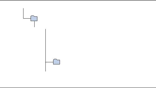
The installation program creates the Cyclone V GX FPGA Development Kit directory structure shown in Figure 3–1.
Figure 3–1. Cyclone V GX FPGA Development Kit Installed Directory Structure (1)
 <install dir>
The default Windows installation directory is C:\altera\<version>\.
kits
 cycloneVGX_5cgxfc7df31_fpga
 board_design_files
 demos
demos  documents
examples
 factory_recovery
Note to Figure 3–1:
(1) Early-release versions might have slightly different directory names.
Table 3–1 lists the file directory names and a description of their contents.
Table 3–1. Installed Directory Contents
Directory Name |
Description of Contents |
|
|
|
|
board_design_files |
Contains schematic, layout, assembly, and bill of material board design files. Use these files as a |
|
starting point for a new prototype board design. |
||
|
||
|
|
|
demos |
Contains demonstration applications. |
|
|
|
|
documents |
Contains the kit documentation. |
|
|
|
|
examples |
Contains the sample design files for the Cyclone V GX FPGA Development Kit. |
|
|
|
|
factory_recovery |
Contains the original data programmed onto the board before shipment. Use this data to restore |
|
the board with its original factory contents. |
||
|
||
|
|
Installing the USB-Blaster II Driver
The Cyclone V GX FPGA development board includes integrated USB-Blaster circuitry for FPGA programming. However, for the host computer and board to communicate, you must install the On-Board USB-Blaster II driver on the host computer.
fInstallation instructions for the On-Board USB-Blaster II driver for your operating system are available on the Altera website. On the Altera Programming Cable Driver Information page of the Altera website, locate the table entry for your configuration and click the link to access the instructions.
f For USB-Blaster II configuration details, refer to the On-Board USB-Blaster II page.
Cyclone V GX FPGA Development Kit |
October 2012 Altera Corporation |
User Guide |
|
4. Development Board Setup
The instructions in this chapter explain how to set up the Cyclone V GX FPGA development board.
Setting Up the Board
To prepare and apply power to the board, perform these steps:
1.The FPGA development board ships with its board switches preconfigured to support the design examples in the kit. If you suspect your board might not be currently configured with the default settings, follow the instructions in “Factory Default Switch Settings” on page 4–2 to return the board to its factory settings before proceeding.
2.The FPGA development board ships with design examples stored in the flash memory device. Verify the DIP switch (SW3.3) is set to the factory off (1) position to load the design stored in the factory portion of flash memory.
1The FPGA development board can be powered by the PCIe host adapter or the laptop power adapter. If you want to power the board by the PCIe host system, plug the FPGA development card into a standard PCIe connector. Alternatively, to power the FPGA development board using the laptop power adaptor, perform the following two steps:
3.Connect the 65 W, 15 VDC @ 4.3 A power supply to the DC Power Jack (J9) on the FPGA board and plug the cord into a power outlet.
c Use only the supplied power supply. Power regulation circuitry on the board can be damaged by power supplies with greater voltage, and a lower-rated power supply may not be able to provide enough power for the board.
4.Set the POWER switch (SW1) to the on position. When power is supplied to the board, blue LED (D23) illuminates indicating that the board has power.
The MAX V device on the board contains (among other things) a parallel flash loader (PFL) megafunction. When the board powers up, the PFL reads a design from flash memory and configures the FPGA. The DIP switch (SW3.3) controls which design to load. When the switch is in the factory off (1) position, the PFL loads the design from the factory portion of flash memory.
1The kit includes a MAX V design which contains the MAX V PFL megafunction. The design resides in the <install dir>\kits\cycloneVGX_5cgxfc7df31_fpga\examples\max5 directory.
When configuration is complete, the Config Done LED (D15) illuminates, signaling that the Cyclone V GX device configured successfully.
October 2012 Altera Corporation |
Cyclone V GX FPGA Development Kit |
|
User Guide |
4–2 |
Chapter 4: Development Board Setup |
|
Factory Default Switch Settings |
|
|
fFor more information about the PFL megafunction, refer to Parallel Flash Loader Megafunction User Guide.
Factory Default Switch Settings
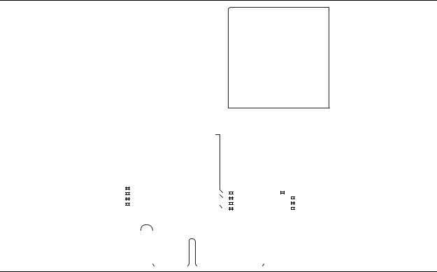
This section shows the factory switch settings (Figure 4–1) for the Cyclone V GX FPGA development board.
Figure 4–1. Switch Locations and Default Settings
PCIE_PRSNT2n_x1 PCIE_PRSNT2n_x4
-
FAN_FORCE_ON
|
|
|
|
|
|
|
CLK SEL |
||
|
SW3 |
|
|
|
ON |
CLK EN |
|||
|
|
|
|
||||||
|
|
|
|
|
|||||
|
|
|
|
|
FACT LOAD |
||||
|
|
|
|
|
|
|
|||
|
|
|
|
|
|
|
SEC MODE |
||
|
|
|
|
|
|
|
|||
|
Off |
On |
|||||||
|
|
|
|
|
|
|
|
|
|
|
|
|
|
|
|
|
|
|
|
|
|
|
|
|
|
|
|
|
|
|
|
|
|
|
|
|
|
|
|
|
|
|
|
|
|
|
|
|
|
|
|
SW4 |
|
SW5 |
5M2210_JTAG_EN |
|||||||||
|
|
|
|
|
ON |
|
|
|
|
|
|
|
ON |
|
|
|
|
|
|
|
|
|
|
|
|
|
|
|
HSMA_JTAG_EN |
|
|
|
|
|
|
|
|
|
|
|
|
|
|
PCIE_JTAG_EN |
|
|
|
|
|
|
|
|
|
|
|
|
|
|
|
|
|
|
|
|
|
|
|
|
|
|
|
|
|
- |
|
|
|
|
|
|
|
|
|
|
|
|
|
|
|
Off On |
Off On |
|||||||||||||
|
|
|
|
|
|
|
|
|
|
|
|
|
|
|
|
|
|
|
|
|
|
|
|
|
|
|
|
|
|
To restore the switches to their factory default settings, perform these steps: 1. Set the DIP switch bank (SW3) to match Table 4–1 and Figure 4–1.
Table 4–1. SW3 DIP Switch Settings (Part 1 of 2)
Switch |
Board |
Function |
Default |
|
Label |
Position |
|||
|
|
|||
|
|
|
|
|
|
|
Switch 1 has the following options: |
|
|
1 |
CLK SEL |
■ On (0) = SMA input clock is selected. |
Off |
|
■ Off (1) = Programmable oscillator clock is |
||||
|
|
|
||
|
|
selected. |
|
|
|
|
|
|
|
|
|
Switch 2 has the following options: |
|
|
2 |
CLK EN |
■ On (0) = On-board oscillator is disabled. |
Off |
|
|
|
■ Off (1) = On-board oscillator is enabled. |
|
|
|
|
|
|
Cyclone V GX FPGA Development Kit |
October 2012 Altera Corporation |
User Guide |
|
Loading...