


AlphaNet™ IDH4 Series DOCSIS® Status Monitor for XM2, XM2-HP, and XM2-300HP Series CableUPS™
Installation and Quick Start Guide
The AlphaNet IDH4 Series Embedded DOCSIS Transponder allows monitoring of Alpha power supplies through existing cable network infrastructure. Advanced networking services provide quick reporting and access to critical powering information.
The IDH4 Series utilizes Simple Network Management Protocol (SNMP) and standard Management Information Bases (MIBs) to provide network status monitoring and diagnostics. A Web interface enables authorized personnel direct access to advanced diagnostics using a common Web browser. No custom software or proprietary cables are required.
The transponders can be installed and configured for operation in the XM2, XM2-HP, or XM2-300HP Power Supply.
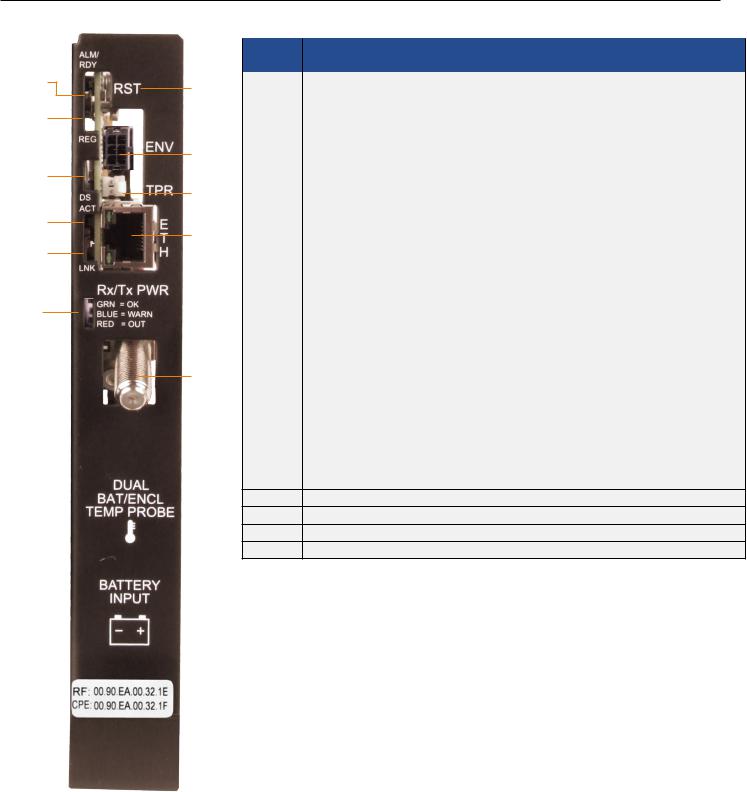
IDH4X DOCSIS Transponder
1
2
3
4
5
6
7
8
9
10
11
12
13
14
15
16
17
18
Item |
LED or Connector |
Status |
Behavior |
Indication |
|
|
|
N/A |
OFF |
No power or malfunctioning IDH4 Series |
|
|
|
|
|
|
|
|
|
GRN |
ON |
Reset of the IDH4 Series is in process |
|
|
|
|
|
||
1 |
ALM/RDY: Alarm and Ready |
Steady Blinking |
Normal operation |
||
|
|||||
|
|
|
|||
|
Blinking more |
Minor Alarm |
|||
|
|
|
|||
|
|
|
OFF than ON |
||
|
|
RED |
|
||
|
|
|
|
||
|
|
Blinking more |
Major Alarm |
||
|
|
|
|||
|
|
|
ON than OFF |
||
|
|
|
|
||
|
|
|
|
|
|
|
|
|
OFF |
No power, upstream frequency undetermined |
|
|
|
|
|
|
|
2 |
REG: Upstream ranging and |
GRN |
BLINKING |
Power on, downstream locked, upstream frequency ranging, |
|
registration lock |
DHCP request in progress |
||||
|
|
|
|||
|
|
|
ON |
CMTS registration completed |
|
|
|
|
|
|
|
|
DS: Downstream RF Carrier |
|
OFF |
No power / downstream carrier |
|
3 |
GRN |
|
|
||
BLINKING |
Power on, downstream carrier frequency searching |
||||
detection and lock |
|||||
|
|
|
|
||
|
|
|
ON |
Downstream carrier lock |
|
|
|
|
|
|
|
|
|
|
OFF |
No Ethernet communications activity |
|
4 |
ACT: CPE Activity status |
GRN |
|
|
|
BLINKING |
Momentary flashes during CPE communications via the Ethernet |
||||
|
|
|
craft port |
||
|
|
|
|
||
5 |
LNK: CPE Link status |
GRN |
OFF |
No Ethernet link |
|
|
|
||||
ON |
Link on Ethernet Craft port |
||||
|
|
|
|||
|
|
|
|
|
|
|
|
|
OFF |
No RF detected |
|
|
|
|
|
|
|
|
|
|
Blue |
Rx/Tx Power at a warning level as set within the SCTE-HMS |
|
|
RF Rx/Tx Power Level |
|
Property Table |
||
6 |
TRI |
|
|||
Indicator |
Green |
Rx/Tx RF Power level within tolerance |
|||
|
|
||||
|
|
|
|
|
|
|
|
|
Red |
Rx/Tx Power at an alert level as set within the SCTE-HMS |
|
|
|
|
Property Table |
||
|
|
|
|
||
|
COM: AlphaBus |
|
OFF |
No AlphaBus Communications |
|
7 |
GRN |
|
|
||
|
|
||||
communications |
BLINKING |
Momentary flashes -AlphaBus Port communications active |
|||
|
|
||||
|
|
|
|
|
|
8 |
BAT A/B |
GRN |
ON |
Battery string(s) connected correctly |
|
|
|
||||
OFF |
Battery string(s) not connected correctly |
||||
|
|
|
|||
|
|
|
|
|
|
9 |
BAT A/B Connector |
|
|
|
|
|
|
|
|
|
|
10 |
BAT C/D |
GRN |
ON |
Battery string(s) connected correctly |
|
|
|
||||
OFF |
Battery string(s) not connected correctly |
||||
|
|
|
|||
|
|
|
|
|
11BAT C/D Connector
12RST: Reset buttton
13ENV: Environmental Control connector
14TPR: Tamper Switch connector
15ETH: Ethernet connection
16RF Connection
17COM: AlphaBus Communications connector
18RF, CPE MAC Address label
Fig. 1, IDH4X Transponder Front Panel Indicators and Connectors
746-257-B0-001 Rev. A (2/2014) |
1 |
IDH4L DOCSIS Transponder
1
2
3
4
5
6
|
|
Item |
LED or |
Status |
Behavior |
Indication |
|
|
Connector |
||||
|
|
|
|
|
|
|
7 |
|
|
|
N/A |
OFF |
No power or malfunctioning transponder |
|
|
|
|
|
|
|
|
|
|
GRN |
ON |
Transponder reset in process |
|
|
|
|
|
|||
|
|
|
|
|
|
|
1 |
|
ALM/RDY: Alarm and |
Steady Blinking |
Normal operation |
||
|
|
|||||
|
|
|
|
|||
|
Ready |
|
Blinking more OFF |
Minor Alarm |
||
|
|
|
|
|||
8 |
|
|
|
|
than ON |
|
|
|
|
RED |
|
||
|
|
|
|
|
||
|
|
|
Blinking more ON |
Major Alarm |
||
|
|
|
|
|
||
|
|
|
|
|
than OFF |
|
|
|
|
|
|
|
|
|
|
|
|
|
|
|
9 |
|
|
|
|
OFF |
No power, upstream frequency undetermined |
2 |
|
REG: Upstream ranging |
GRN |
BLINKING |
Power on, downstream locked, upstream frequency |
|
|
and registration lock |
ranging, DHCP request pending |
||||
|
|
|
|
|
||
10 |
|
|
|
|
|
|
|
|
|
|
ON |
CMTS registration completed |
|
|
|
|
DS: Downstream RF |
|
OFF |
No power / downstream carrier |
|
|
|
|
|
|
|
3 |
|
Carrier detection and |
GRN |
BLINKING |
Power on, downstream carrier frequency searching |
|
|
|
|
lock. |
|
|
|
|
|
|
|
ON |
Downstream carrier lock |
|
|
|
|
|
|
||
|
|
|
|
|
|
|
|
|
|
|
|
OFF |
No Ethernet communications activity |
4 |
|
ACT: CPE Activity status |
GRN |
|
|
|
|
BLINKING |
Momentary flashes during CPE communications via the |
||||
|
|
|
|
|
Ethernet Craft port |
|
|
|
|
|
|
|
|
5 |
|
LNK: CPE Link status |
GRN |
OFF |
No link |
|
|
|
|
||||
|
ON |
Link on Ethernet Craft port |
||||
11 |
|
|
|
|
||
|
|
|
|
|
|
|
|
|
|
|
OFF |
No RF detected |
|
|
|
|
|
|
||
|
|
|
|
|
|
|
|
|
|
|
|
Blue |
Rx/Tx Power at a warning level as set within the SCTE- |
|
|
|
RF Rx/Tx Power Level |
|
HMS Property Table |
|
6 |
|
TRI |
|
|||
|
Indicator |
Green |
Rx/Tx RF Power level within tolerance |
|||
|
|
|
|
|||
|
|
|
|
|
|
|
|
|
|
|
|
Red |
Rx/Tx Power at an alert level as set within the SCTE-HMS |
|
|
|
|
|
Property Table |
|
|
|
|
|
|
|
|
7RST: Reset buttton
8ENV: Environmental Control connector
9TPR: Tamper Switch connector
10ETH: Ethernet connection
11RF Connection
Fig. 2, IDH4L Transponder Front Panel Indicators and Connectors
746-257-B0-001 Rev. A (2/2014) |
2 |

Overview
 CAUTION!
For units in service, backup battery power will not be available during this procedure.
IDH4 Series installation and setup is comprised of three basic steps:
1.Configuring the Network: Provisioning the DHCP Server with the transponder’s MAC Address and assigning it a
DOCSIS Configuration File.
2.Setting Options: The IDH4 Series is designed for out-of-the-box, "plug and play" operation, but non-default settings such as SNMP trap destination addresses may be required for the Network Management System (NMS). SNMP trap addresses can be set automatically via the DOCSIS Configuration File per RFC 4639, while IDH4 Series proprietary options may be set through type-11 TLV entries. The SCTE-HMS and Alpha MIBs may need to be compiled into a MIB browser before it can be used to monitor or set transponder and power supply parameters. Refer to the IDH4 for XM2 and XM2-HP Technical Manual (Alpha p/n 746-257-B2-001) for details.
3.Installation:Installation of the IDH4 Series into the power supply, connecting the RF Cable, battery sense wire harnesses (IDH4X only), Environmental, Tamper switch, Ethernet, and verifying operation.
These steps can be performed independently of one another. However, configuring the network prior to field installation will allow the installation to be verified while personnel are still on-site. Performing field installation before network configuration and before the installation can be verified, might result in additional field service calls to correct mistakes.
IDH4X Installation / Replacement Procedure in XM2 and XM2-HP Power
Supplies
1.Before removing the Inverter Module (IM), verify the power supply device address is correct.
The power supply device address must not be set to zero and no two power supplies monitored by a single IDH4 Series can have the same address. Power supplies must have 1, 2, 3, 4 or 5 as an address.
To verify the power supply’s address, go to the LCD display on the inverter module and enter the "Setup" menu. Scroll to the "Device Address" menu item and verify the device address is set to something other than 0 (Zero).
2.Switch OFF the power supply’s battery breaker.
NOTE:
With the battery breaker in the OFF position, the power supply will not go into inverter mode.
3.Unplug all Inverter Module connections (e.g. battery cable, remote temperature sensor).
4.Loosen the Inverter Module thumbscrews and slide the inverter module out just enough to disconnect the ribbon cable. Disconnect the ribbon cable.
5.Slide the Inverter Module out of the power supply.
746-257-B0-001 Rev. A (2/2014) |
3 |
 Loading...