


FXM 650
Table of contents
 Loading...
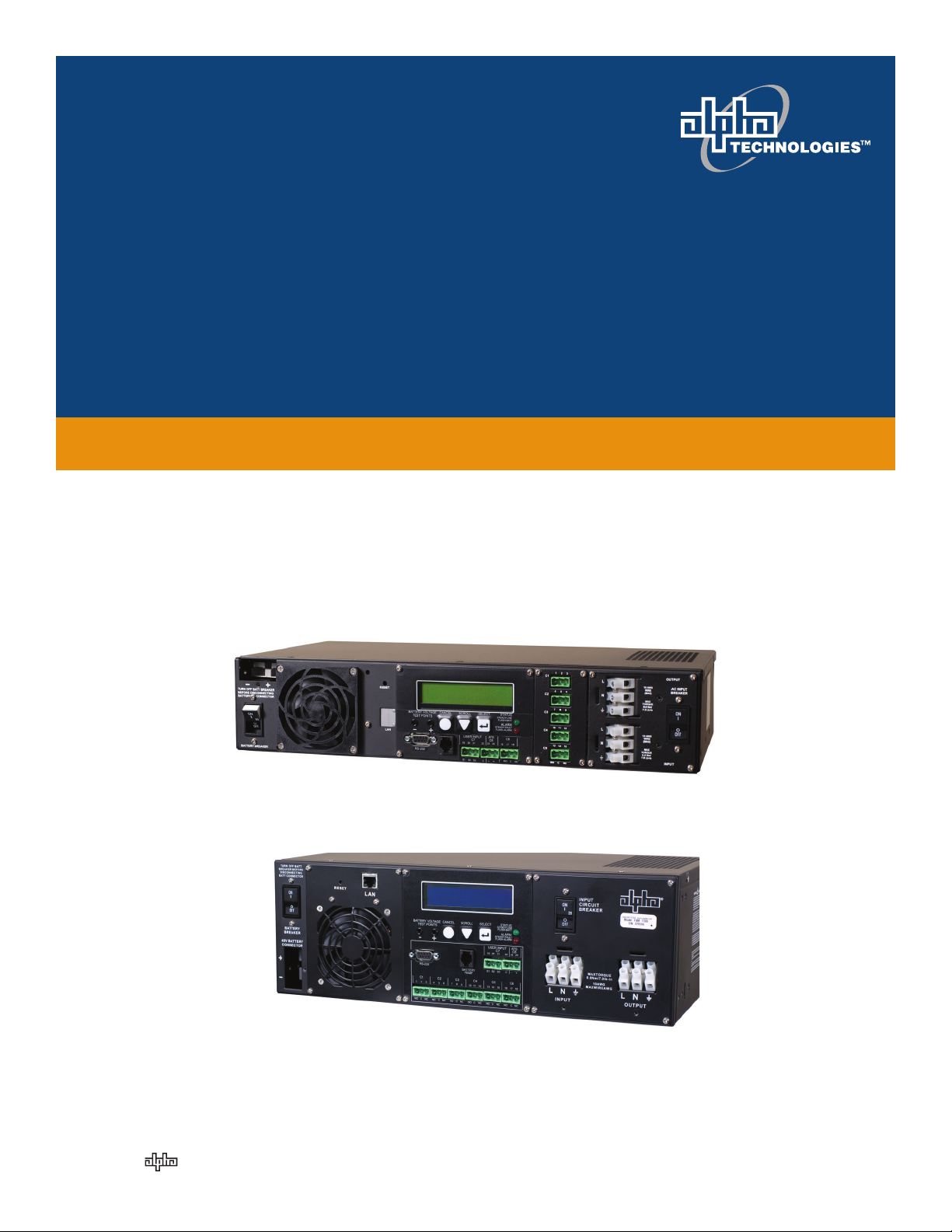
Alpha FXM 650, 1100, 2000 UPS
Installation & Operation Manual
Part # 017-230-B4
Effective: 07/2013
member of The Group
™
Your Power Solutions Partner


Alpha FXM 650, 1100, 2000 UPS
Installation and Operation Manual
NOTE:
Photographs contained in this manual are for illustrative purposes only. These photographs may not match your installation.
NOTE:
Operator is cautioned to review the drawings and illustrations contained in this manual
before proceeding. If there are questions regarding the safe operation of this powering
system, contact Alpha Technologies or your nearest Alpha representative.
NOTE:
Alpha shall not be held liable for any damage or injury involving its enclosures, power
supplies, generators, batteries, or other hardware if used or operated in any manner or
subject to any condition inconsistent with its intended purpose, or if installed or operated in an unapproved manner, or improperly maintained.
For technical support, contact Alpha Technologies:
Canada and USA: 1-888-462-7487
International: +1-604-436-5547
Copyright
Copyright © 2013 Alpha Technologies Ltd. All rights reserved. Alpha is a registered trademark of Alpha Technologies.
No part of this documentation shall be reproduced, stored in a retrieval system, translated, transcribed, or transmitted in any form or by any means manual, electric, electronic, electromechanical, chemical, optical, or otherwise without prior explicit written permission from Alpha Technologies.
This document, the software it describes, and the information and know-how they contain constitute the proprietary, confidential and valuable trade secret information of Alpha Technologies, and may not be used for any
unauthorized purpose, or disclosed to others without the prior written permission of Alpha Technologies.
The material contained in this document is for information only and is subject to change without notice. While
reasonable efforts have been made in the preparation of this document to assure its accuracy, Alpha Technologies assumes no liability resulting from errors or omissions in this document, or from the use of the information
contained herein. Alpha Technologies reserves the right to make changes in the product design without reservation and without notification to its users.

Table of Contents
1. Safety ....................................................................................................................................4
1.1 Safety Symbols .................................................................................................................... 4
1.2 General Warnings and Cautions .......................................................................................... 5
1.3 Certications and Compliances ............................................................................................ 6
2. General Description ..............................................................................................................7
2.1 Overview .............................................................................................................................. 7
2.2 Front Panel ........................................................................................................................... 7
3. Site Planning ....................................................................................................................... 11
3.1 Safety Precautions ..............................................................................................................11
3.2 Communicating with the Alpha FXM .................................................................................. 12
3.3 Electromagnetic Compatibility (EMC) Requirements ......................................................... 13
4. Unpacking Alpha FXM ........................................................................................................14
5. Installation ...........................................................................................................................15
5.1 Tools and Equipment Required for Installation ................................................................... 15
5.2 Mounting the Alpha FXM .................................................................................................... 16
5.3 Wiring the External Batteries .............................................................................................. 17
5.4 UATS and (UGTS) Option .................................................................................................. 19
6. Operating the Alpha FXM....................................................................................................20
6.1 Switching the Alpha FXM On and Off ................................................................................. 20
6.2 Operating from the Control Panel Interface ....................................................................... 21
6.3 Operating via the FXM Communication Module (Intranet or Internet) ............................... 30
6.4 The Alpha UPS Monitor Interface ....................................................................................... 56
6.5 HyperTerminal Interface ..................................................................................................... 60
7. Maintenance .......................................................................................................................72
7.1 Upgrading the FXM Firmware ............................................................................................ 72
7.2 Testing and Replacing the Batteries ................................................................................... 74
7.3 Preventative Maintenance .................................................................................................. 77
8. Troubleshooting ..................................................................................................................78
8.1 Procedure ........................................................................................................................... 78
2
017-230-B4 Rev B

9. Specications ...................................................................................................................... 80
10. Warranty ...........................................................................................................................83
11. Emergency Shutdown Procedure .....................................................................................84
Appendix A - Peukert Number and Battery Capacity ................................................................ 85
A.1 Introduction ....................................................................................................................... 85
A.2 Determining the Peukert’s Number and Peukert’s Capacity ............................................. 85
A.3 Determining Peukert’s Capacity for Series Parallel Combinations ................................... 85
A.4 Example ............................................................................................................................ 86
A.5 Using the Spreadsheet ......................................................................................................87
Appendix B - Types of Triggers ................................................................................................88
B.1 Edge trigger ...................................................................................................................... 88
B.2 Level Toggle ...................................................................................................................... 88
017-230-B4 Rev B
3
1. Safety
SAVE THESE INSTRUCTIONS: This manual contains important safety instructions that
must be followed during the installation, servicing, and maintenance of the product. Keep it in a safe place. Review the drawings and illustrations contained in this manual before proceeding. If there are any questions regarding the safe installation or operation of this product, contact Alpha Technologies or the nearest Alpha representative. Save this document for future reference.
1.1 Safety Symbols
To reduce the risk of injury or death, and to ensure the continued safe operation of this product, the following
symbols have been placed throughout this manual. Where these symbols appear, use extra care and attention.
The use of ATTENTION indicates specic regulatory/code requirements that may affect the
placement of equipment and /or installation procedures.
NOTE:
A NOTE provides additional information to help complete a specic task or procedure.
Notes are designated with a checkmark, the word NOTE, and a rule beneath which the
information appears.
CAUTION!
CAUTION indicates safety information intended to PREVENT DAMAGE to material or
equipment. Cautions are designated with a yellow warning triangle, the word CAUTION,
and a rule beneath which the information appears.
WARNING!
WARNING presents safety information to PREVENT INJURY OR DEATH to personnel.
Warnings are indicated by a shock hazard icon, the word WARNING, and a rule beneath
which the information appears.
HOT!
The use of HOT presents safety information to PREVENT BURNS to the technician or
user.
4
017-230-B4 Rev B

1.2 General Warnings and Cautions
You must read and understand the following warnings before installing the Alpha FXM and its components. Failure to do so could result in personal injury or death.
• Read and follow all instructions included in this manual.
• Do not work alone under hazardous conditions.
• Only qualified personnel are allowed to install, operate and service this system and its components.
• Use proper lifting techniques whenever handling equipment, parts, or batteries.
• Always assume electrical connections or conductors are live. Switch off all circuit breakers and double-
check connections with a voltmeter before performing installation or maintenance.
• Place warning label(s) on the utility panel to tell emergency personnel a UPS is installed.
• The Alpha FXM uses more than one live circuit. AC power may be present at the outputs even if the system
is disconnected from line or battery power.
• The Alpha FXM surface can be very hot to the touch.
• Battery installation and servicing should be done or supervised by personnel knowledgeable about batteries
and their safety procedures.
• If electrolyte splashes on your skin, immediately wash the affected area with water. If electrolyte gets into
your eyes, wash them for at least 10 minutes with clean running water or a special neutralizing eye wash
solution. Seek medical attention at once.
• Neutralize spilled electrolyte with special neutralizing solutions in a “spill kit” or a solution of 1 lb. (0.45 kg) of
baking soda (bicarbonate of soda) in 1 gallon (3.8 L) of water.
• Be extra cautious when connecting or adjusting battery cabling. An improperly connected battery cable or
an unconnected battery cable can result in arcing, fire, or explosion.
• Use new batteries when installing a new unit. Verify that all batteries are the same type with identical date
codes.
• Always replace batteries with ones of identical number, type and rating. Never install old or untested batteries. One sealed lead-acid battery is rated to a maximum voltage of 12 Vdc.
• A battery that shows signs of cracking, leaking or swelling must be replaced immediately by authorized personnel using a battery of identical type and rating.
• Keep the chassis area clear and dust-free during and after installation.
• Keep tools away from walk areas where you or others could fall over them.
• Wear safety glasses when working under any conditions that might be hazardous to your eyes.
• Do not work on the unit or connect or disconnect cables during periods of lightning activity.
• Do not smoke or introduce sparks in the vicinity of a battery.
• Never open or damage the batteries. Released electrolyte is harmful to the skin and eyes. It may be toxic
and hazardous to the environment.
• A battery can present a risk of electrical shock and high short-circuit current. The following precautions
should be observed when working on batteries:
a. Remove watches, rings, or other metal objects.
b. Use tools with insulated handles.
c. Wear rubber gloves and boots.
d. Do not lay tools or metal parts on top of batteries.
e. Disconnect the charging source before connecting or disconnecting battery terminals.
f. Determine if the battery is inadvertently grounded. If inadvertently grounded, remove the source from the
ground. Contact with any part of a grounded battery can result in electrical shock. The likelihood of such
shock can be reduced if the grounds are removed during installation and maintenance (applicable to
equipment and remote battery supplies not having a grounded supply circuit).
017-230-B4 Rev B
5

• Never let live battery wires touch the Alpha FXM, the enclosure or any other metal objects. This can cause a
fire or explosion.
• Never dispose of batteries in a fire. The batteries may explode. Follow the manufacturer’s directions and
check with your local jurisdictions for safe battery disposal.
• Before attaching the batteries to the Alpha FXM, make sure that the polarity is correct.
• If the batteries have been in storage for more than 3 months, recharge them for at least 24 hours and then
test them with a load before installation.
• Each AlphaCell™ battery has a date code, found on the warning label, which must be recorded in the maintenance log. If non-Alpha batteries are used, see the manufacturer’s documentation for date code type and
placement.
1.3 Certifications and Compliances
The Alpha FXM has been designed, manufactured, and tested to the requirements of the following national and
international safety standards:
• CAN/CSA-C22.2 No. 107.3-05 – Uninterruptible Power Systems; additional requirements (RD): CAN/CSAC22.2 No. 60950-1-03 - Information Technology Equipment - Safety.
• UL 1778 (Edition 4) – Uninterruptible Power Systems; additional requirements (RD): UL 60950-1 (Edition 1) Information Technology Equipment - Safety.
• FCC CFR47 Part 15 Class A – This equipment has been tested and found to comply with the limits for a
Class A digital device pursuant to part 15 of the FCC Rules. These limits are designed to provide reasonable
protection against harmful interference when the equipment is operated in a commercial environment. This
equipment generates, uses, and can radiate radio frequency energy and, if not installed and used in accordance with the instruction manual, may cause harmful interference to radio communications. Operation
of this equipment in a residential area is likely to cause harmful interference in which case the user will be
required to correct the interference at his own expense.
• Industry Canada - This Class A digital device apparatus complies with Canadian ICES-003.
• Industry Canada - Cet appareil numrique de la Classe A est conforme la norme NMB-003 du Canada.
6
017-230-B4 Rev B

2. General Description
2.1 Overview
The Alpha FXM is available in 3 models – FXM 650, FXM 1100 and FXM 2000. The FXM 650 and the FXM
1100/2000 look different, but all of the front panel connectors and circuit breakers operate in the same way. However the circuit breakers for each unit have different ratings. See Chapter "9. Specifications" for details. All units
operate in the same way unless stated otherwise in this manual.
• FXM 650-24Vdc – with a 24 Vdc battery string voltage.
• FXM 650-48Vdc – with a 48 Vdc battery string voltage.
• FXM 1100-48Vdc – with a 48 Vdc battery string voltage.
• FXM 2000-48Vdc – with a 48 Vdc battery string voltage.
2.2 Front Panel
Figure 1 shows the front panel connectors and circuit breakers, which are described in detail in the following
sections.
2
1
3
1
4
4
6
7
6
5
5
8
10
C6
8
11
10
9
12
13
14
12
2
017-230-B4 Rev B
3
Figure 1 — FXM 650 (top) and FXM 1100/2000 front panel description
7
11
13
149
7

Battery breaker
1
This circuit breaker provides over-current protection and is used as an on/off switch for the battery power. It must
be switched on for proper Alpha FXM operation.
Battery connector
2
The battery connector connects the external batteries to the Alpha FXM.
Replaceable fan assembly
3
This microprocessor-controlled fan turns on at a programmable temperature to lower the Alpha FXM internal temperature. It must not be blocked. An Alarm is generated if the fan fails; a failed fan can be replaced in the field.
RJ45 communication module connector
4
The RJ-45 connector is the Alpha FXM Ethernet connector.
LCD control panel and menu navigation buttons
5
The LCD control panel together with the cancel, scroll and select buttons are used to monitor and control the
Alpha FXM.
Battery voltage test points
6
These test points accept 2 mm diameter test probe tips. The battery circuit breaker must be on to measure the
voltage.
The battery voltage test points are not to be used as a power outlet.
RS-232
7
This DE-9 connector allows a straight-through DE-9 to DE-9 connector cable to be used to connect the
Alpha FXM to a computer for remote control and monitoring.
Battery temperature sensor connector
8
The battery charging voltage is temperature dependant when compensation is not set to 0 mV/°C/cell. A battery
temperature sensor connects to the Alpha FXM so the Alpha FXM microprocessor can adjust the charging voltage for optimum charging. Refer to "UPS Maintenance > Battery" on page 38.
The sensor MUST be attached to the Alpha FXM for normal operation. If the sensor is not attached, a “Temperature Probe Unplugged” alarm appears on the LCD.
9
Contacts C1 to C6
Contacts C1 to C5 allow the Alpha FXM to be connected to an external monitoring panel or to traffic control
equipment.
The factory default settings can be reprogrammed to meet your requirements. Each contact can only be programmed for one function at a time and cannot show multiple conditions. See "UPS Maintenance > Relay & Load
Shed" on page 41 and section 6.5.7 on page 66 for the HyperTerminal interface.
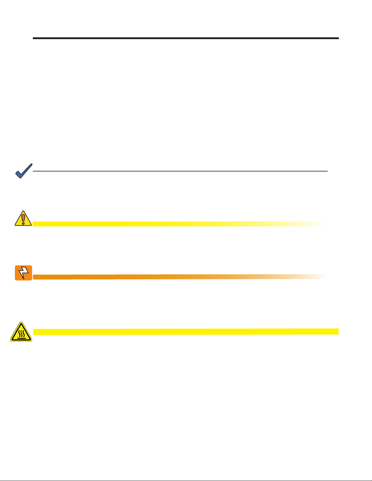
For Contact C6, the default factory configuration is +48 Vdc output (FXM 650-24 is +24 Vdc), but it can be factory configured as a dry contact. Figure 2 shows the contact’s layout while Figure 3 shows the +48 Vdc or +24
Vdc terminal block layout.
Microprocessor
UPS
The contacts have
a maximum rating
of 1A at 250V.
Interior
Normally
Open (NO)
Common(C)
Figure 2 — Contact Layout (Standard for C1 to C5, Factory Option for C6)
8
Normally
Closed (NC)
017-230-B4 Rev B

C1: The C1 contact is energized when line power is unqualified and the Alpha FXM provides backup battery
power to the load(s). It can be used to generate an “On Battery” contact.
C2, C3: These contacts are energized when the battery drops below a pre-set voltage level. They can be used to
generate a Low Battery alarm. To change the pre-programmed level to match the batteries used and the actual
operating conditions, see Low Battery Warning in "UPS Maintenance > Battery" on page 38.
C4: This contact is energized after the Alpha FXM has been in Inverter mode for 2 hours.
To change the pre-programmed 2 hours to match your operating conditions, see Load Shed Timer Configura-
tion in "UPS Maintenance > Relay & Load Shed" on page 41.
C5: The C5 contact is energized when any alarm is generated—see "Table P — Alarm Submenu" on page 78.
C6: The factory default layout for the C6 contact is a relay that is energized when the Alpha FXM is in Line or
Inverter modes and is de-energized when in Standby mode. It provides 48 Vdc (500 mA) from the external batteries to an external fan or other equipment. C6 can be factory-configured as a dry contact.
Microprocessor
+48Vdc, 500mA
(FXM 1100/2000, 650-
48) or +24Vdc (FXM
650-24) from the
external batteries.
Contact
C6
16 17
Figure 3 — 48 Vdc Contact Layout (De-energized Shown, Factory Default for C6)
Optically isolated user inputs C7 and contacts C8
10
18
The optically isolated user inputs are used to attach an external switch panel for remote control of the Alpha FXM
or to allow the Alpha FXM to control optional Alpha Off-Line Automatic Transfer Switch (ATS).
User Input (C7): This relay has three contacts that are used to control the Alpha FXM:
19 (S1) : Shorting this contact starts the Alpha FXM self test. See "UPS Maintenance > Battery" on page 38.
20 (S2): Shorting this contact activates an alarm. See "UPS Maintenance > User Input" on page 46.
21 (S3): Shorting this contact disables the AC output. There is no AC output power, but the Alpha FXM is still
energized. A manual restart is required to put the Alpha FXM back to normal operation.
22 (C): Isolated return for contacts S1, S2 and S3.
017-230-B4 Rev B
19
S1:Self Test20S2:Alarm21S3:Shutdown22Common
Figure 4 — User Input Layout
9
ATS (C8): When the Alpha FXM is in the Inverter mode, this normally open relay closes sending 48 Vdc (FXM
650-48, 1100, 2000) or 24 Vdc (FXM 650-24) from the external batteries to this dry contact (Figure 5). If the optional Alpha Off-Line Automatic Transfer Switch (ATS) is connected, it will cause the ATS to switch the load from
line power to the Alpha FXM battery backup power.
Contact C8
48Vdc from the
external batteries
Microprocessor
+
23
Figure 5 — ATS Layout
11
Status and Alarm LEDs
Status:
Green LED solidly illuminated: the Alpha FXM is in Line mode and line power is provided to the load.
Green LED flashing: the unit is in Inverter mode and backup battery power is provided to the load.
Alarm:
Red LED solidly illuminated: fault in the Alpha FXM. (See "Table Q — Fault Submenu" on page 79.)
Red LED flashing indicates an alarm. (See "Table P — Alarm Submenu" on page 78.)
24
AC Input Circuit Breaker
12
This circuit breaker is an on/off switch for the line power into the Alpha FXM that also provides input protection. It
must be switched on for proper Alpha FXM operation.
13
Input Terminal Block
This terminal block is the Alpha FXM AC line power input.
14
Output Terminal Block
This terminal block is the Alpha FXM AC power output.
10
017-230-B4 Rev B

3. Site Planning
WARNING!
Restricted Access: The Alpha FXM must be installed in a restricted area accessible only
by qualied service personnel.
The Alpha FXM is intended for permanent AC connection only. The only exception is the
FXM650(U) model.
The Alpha FXM must be correctly grounded for proper operation. Older facilities may
have inadequate electrical grounding. Inspection must be performed by a qualied electrician before installation to ensure that grounding meets the local electrical code.
The utility line attached to the Alpha FXM input MUST be protected by a circuit breaker
certied for this use in accordance with the local electrical code. The UPS must be connected only to a dedicated branch circuit.
The UPS equipment that is powered by this service panel requires the neutral to be permanently bonded to the ground. Always disconnect the batteries before servicing the
circuit breaker panel.
The input and output lines to and from the Alpha FXM MUST have disconnect devices
attached.
The Alpha FXM is suitable for installations in Network Telecommunication Facilities and locations where the
National Electrical Code applies.
Grounding: The Alpha FXM is suitable both for installation as part of a common bonding network and an isolated bonding network.
For installations above 1400 m (4500 ft) elevation, additional cooling may be needed to reduce the operating
temperature of the Alpha FXM. The maximum allowable operating temperature must be reduced by 2°C (3.5
°F) for every 300 m (1000 ft) above 1400 m (4500 ft).
3.1 Safety Precautions
• Install the Alpha FXM on a surface that can support its weight. See Chapter "9. Specifications".
• The input wiring must reach a suitably grounded power outlet and the load wiring must reach the
Alpha FXM output terminal blocks.
• Place the Alpha FXM in a properly sheltered location or inside a weather-proof enclosure to protect the
electronics from water, dust and other possible contamination.
• Alpha Technologies offers a wide range of outdoor enclosure systems. Visit our website at www.alpha.ca,
or call customer service for more information.
• Backup Generator (If used)
Use Generator mode so that noise tolerance is increased to accept the fluctuations created by a generator. See Sense Type in Table B on page 24 .
Use a generator with electronic speed and voltage controls which produces less than 10% voltage total harmonic distortion (THD). Mechanical governors can force the Alpha FXM to run continuously in the
Inverter mode.
Before installation, make sure the generator’s output voltage is compatible with the Alpha FXM input voltage requirements. To make sure the system runs smoothly, use a generator that supplies twice as much
power as drawn by the total load.
017-230-B4 Rev B
11
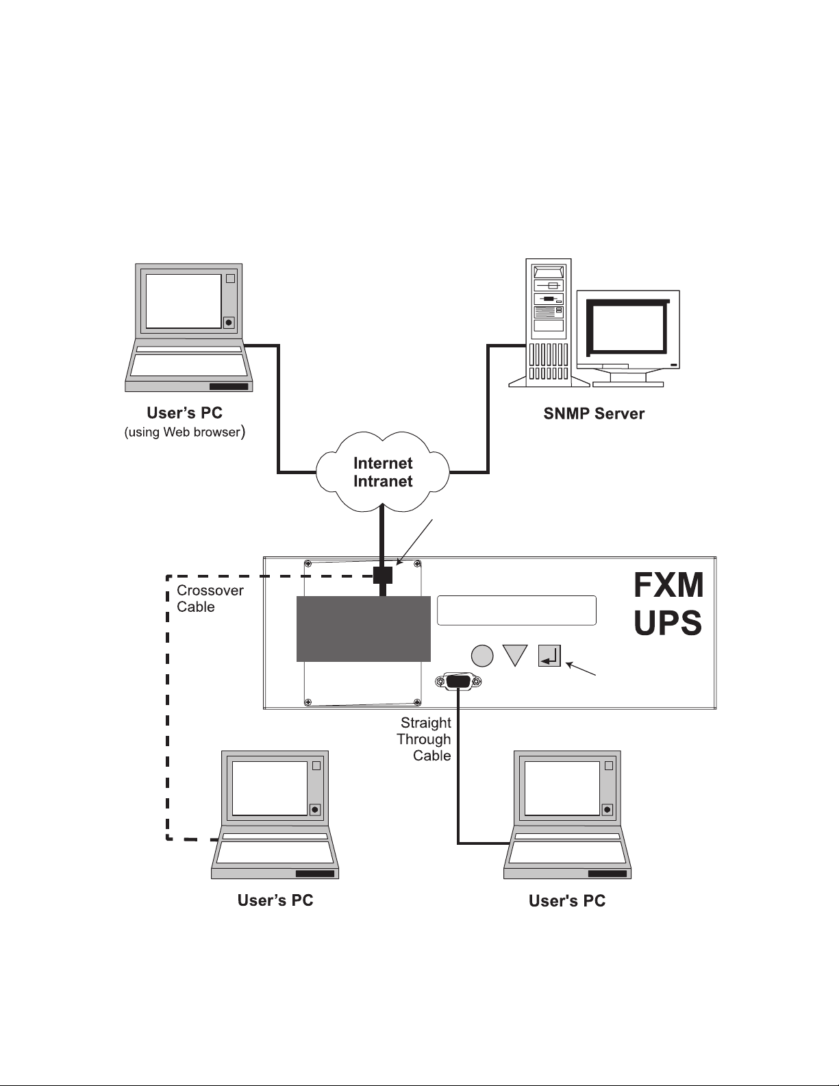
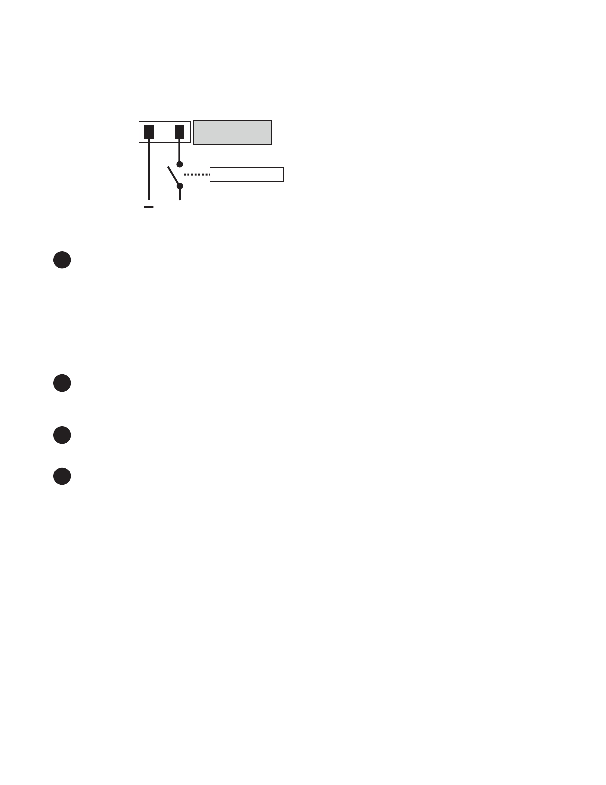
3.2 Communicating with the Alpha FXM
There are several ways you can communicate with the Alpha FXM UPS:
1. Using the control panel.
2. Using an RS-232 interface, you can access the UPS command line system with Windows HyperTerminal or
other terminal emulation program.
3. Using an RS-232 serial connection via the Alpha UPS Monitor installed on your computer. The
Alpha UPS Monitor software can be downloaded from www.alpha.ca/downloads/.
4. Using the optional factory-installed FXM communication module, you can communicate with the Alpha FXM
over a company intranet or the internet using a web browser or with SNMP communications.
Option 4
Option 4
On-Site
Ethernet Connection
Option 4
FXM
Communication
Module
Ethernet Port
Note: FXM Communication Module
is a factory-installed option
SCROLL
120/60/N
LINE
SELECT
Alpha
FXM 2000
CANCEL
RS-232 Port
Options
2 & 3
Option 1:
Control Panel
12
(Using Web browser for
Ethernet connection
to on-site computer)
Figure 6 — Alpha FXM Communication Options
(Using HyperTerminal or Alpha UPS Monitor
available at www.alpha.ca)
017-230-B4 Rev B

3.3 Electromagnetic Compatibility (EMC) Requirements
Observe the following EMC requirements when setting up the Alpha FXM and its internal equipment:
• All AC mains and external supply conductors must be enclosed in a metal conduit or raceway when specified by local, national, and/or other applicable government codes and regulations.
• The customer facilities must provide suitable surge protection.
017-230-B4 Rev B
13

4. Unpacking Alpha FXM
WARNING!
The Alpha FXM is heavy, up to 16 kg (35 lb). Use proper lifting techniques. The lifting
and moving should be done by at least two people to avoid injury.
Follow these guidelines for unpacking the Alpha FXM.
1. Select a suitable area for unpacking.
2. Store all the packing material and boxes for possible equipment returns.
3. Compare the packing slip and the list of parts with the items you received: make sure the standard items as
well as purchased options are included:
Standard items
1 Alpha FXM
1 Alpha FXM operator manual
Terminal blocks and labels for the dry contacts
8
1 Temperature sensor cable
Purchased options
• Batteries, if ordered from Alpha, will be shipped separately.
• Enclosure (with optional mounting hardware kit)
• Battery heating mats
• Network Interface card
• In-line fuse
4. If the list of parts on your packing slip does not match the items you received, or any items appear damaged,
immediately notify your carrier agent and the supplier who prepared your shipment.
14
017-230-B4 Rev B

5. Installation
WARNING!
The Alpha FXM module MUST be correctly grounded for proper operation.
The input and output lines to and from the Alpha FXM MUST have disconnect devices
attached.
The Alpha FXM must be installed in a restricted area accessible only by qualied service personnel.
Once the installation location has been planned and prepared, you are ready to install the Alpha FXM. There are
three steps to setting up the Alpha FXM:
1. Mounting the Alpha FXM
2. Wiring the external batteries
3. Wiring the Alpha FXM
5.1 Tools and Equipment Required for Installation
• DC voltmeter.
• Labels or masking tape and marker.
• Torque wrench for input/output terminal blocks.
• Slot head screwdriver to fit the terminal blocks.
• Minimum #10 AWG copper wire for input/output terminal blocks.
• High strength, flame-proof tape such as duct tape.
• Battery terminal corrosion inhibitor such as NOCO Company NCP-2 or Sanchem Inc. No-Ox ID Grease “A”.
017-230-B4 Rev B
15

5.2 Mounting the Alpha FXM
The Alpha FXM can be placed on a shelf with no other parts needed. Any version of the FXM can be rack or wall
mounted or secured to a shelf, such as on an outdoor enclosure shelf, with the optional mounting brackets as
shown in the figure below The brackets and the screws to attach them to the Alpha FXM case are available from
Alpha Technologies (part number 740-697-21).
CAUTION!
Terminal block covers and the battery harness restraining bracket MUST be used and
are available from Alpha Technologies (part number 740-698-21). If the Alpha FXM end
application is mounted inside an enclosure or in an area restricted to authorized personnel, then the covers and bracket may or may not be needed.
To meet NEBS Level 1 specifications when you are installing this unit in a rack or frame, do the following:
1. Before installation, clean all attachment points on the Alpha FXM, rack and mounting brackets and bring
them to a bright finish. Then coat them with an anti-oxidant such as Sanchem Inc. No-Ox ID “A-Special
Electrical Grade” or equivalent.
2. Attach the mounting brackets with the thread forming screws and the paint piercing washers provided with
the brackets to insure adequate grounding between the Alpha FXM chassis and the rack.
Figure 7 — Mounting the Alpha FXM Mounting brackets position for rack mounting. Rotate to fit either 19" or 23" racks.
For the FXM 1100/2000 units only, the control panel and the power connection panel can be rotated to suit
your needs. To rotate either one, unscrew the screws in each corner, remove the panel, rotate it and reinstall the
screws.
CAUTION!
Use care to avoid damaging or pulling out the wires or the ribbon cables when rotating
the panels.
16
017-230-B4 Rev B

5.3 Wiring the External Batteries
WARNING!
The batteries must be installed by qualied personnel trained in the safe use of high-
energy power supplies and their batteries. Refer to the safety section in this manual.
• Use new batteries when installing a new unit. Verify that all batteries are the same type with identical date
codes.
• For the FXM 650-24, the battery string is 24 Vdc. For the FXM 650-48/1100/2000, the battery string is 48 Vdc.
• If you are making your own battery wiring harness, use at least 10 AWG (for FXM 650/1100) or 8 AWG (FXM
2000) wires.
• The battery return connection is to be treated as an Isolated DC return (DC-I) as defined in GR-1089-CORE.
5.3.1 Procedure
NOTE: The optional in-line fuse option shown in Figure 8 on page 18, is available as part number SPB98-645-
1, Kit, FuseUpgrade, 100A.
1. For FXM 650-48/1100/2000 (48 V battery string), number the batteries from 1 to 4 with labels or tape. For
FXM 650-24 (24 V battery string), number the batteries from 1 to 2 with labels or tape.
2. Coat the battery terminals with the corrosion inhibitor.
3. Connect the batteries as shown in Figure 8 on page 18. If used, install the in-line fuse as shown.
4. Connect the black battery cable to the negative terminal of the battery string, and the red battery cable to the
positive terminal of the battery string.
5. When the batteries are wired, measure the voltage at the battery connection terminals. It should read
between 42 and 54V for the FXM 650-48/1100/2000 or 21 and 27V for the FXM 650-24.
6. Note the polarity and ensure it is correct.
7. Ensure that the DC breaker if OFF.
8. Connect the external batteries to the Battery connector—location 2 in Figure 1.
9. Route the sensor end of the battery temperature cable to the batteries.
10. Attach the battery temperature sensor to the body of the battery, about 2 to 3" (5 to 7.5 cm) from the base of
the battery.
11. If multiple battery strings are used, repeat steps 1 to 4 as required.
017-230-B4 Rev B
17
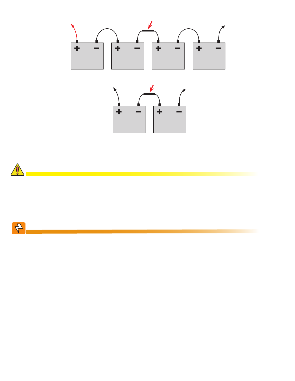
To positive terminal
Battery #4 Battery #3 Battery #2 Battery #1
Optional in-line fuse
To negative terminal
To positive terminal
Battery #2 Battery #1
Figure 8 — External Battery Wiring (for 48 Vdc string (top) and 24 Vdc string)
Optional in-line fuse
To negative terminal
CAUTION!
Torque the battery terminals according to the manufacturer’s specications on the
battery name plate or data sheet.
5.3.2 Wiring the Alpha FXM
WARNING!
Make sure the line power is off. Switch off all circuit breakers on the Alpha FXM before
making any electrical connections.
If stranded wires are used to connect the input and output terminal blocks, ferules or
equivalent crimping terminals must be used.
18
017-230-B4 Rev B

5.3.3 Procedure
1. If used, connect the following ports (see Figure 1 on page 7 for location of numbered elements):
• Ethernet port 4.
• RS-232 port 7.
• Dry contacts 9.
• User inputs 10.
2. Connect the load to the Alpha FXM Output terminal block 14. Torque to 1.4 N-m (12 lb-in).
3. Connect the line power to the Alpha FXM AC Input terminal block 13. Torque to 1.4 N-m (12 lb-in).
4. If needed, attach the terminal block covers and battery harness restraining bracket.
WARNING!
Before proceeding, verify that the line wire is attached to the line terminal block, the
ground wire is attached to the ground terminal block, and the neutral wire is attached to
the neutral terminal block to prevent accidental shocks or electrocutions.
5.4 UATS and (UGTS) Option
The Universal Automatic Transfer Switch (UATS) and Universal Generator Transfer Switch (UGTS) are the next
generation of Automatic Transfer Switch (ATS) and Generator Transfer Switch (GTS) products. They are optional
add-on switching units specifically designed for the FXM UPS family (FXM 650, 1100 and 2000), the Micro UPS
family (Micro 300 and 1000) and the Alpha FXM350/ Micro350 UPS. These switching units provide power and/or
bypass capacity (automatic or manual) so that the operator may safely disconnect the UPS from line or generator
power for easy removal and servicing. In bypass mode, the loads are directly connected to the line or generator
power without any conditioning. Depending on the use of one and/or the other, the UATS/UGTS allows the use
of up to 3 different back-up sources (line, batteries and generator). Refer to the UATS/UGTS Installation Manual
(Alpha P/N 020-165-B0) for details.
WARNING!
Make sure you have read and understood the instructions given in the UATS/UGTS Installation Manual before making any connection to the supply.
017-230-B4 Rev B
19

6. Operating the Alpha FXM
6.1 Switching the Alpha FXM On and Off
Under normal operation, the Alpha FXM is always powered ON to supply uninterruptible power to the load.
Switching off the Alpha FXM will disconnect the power supply to the load. If for any reason you need to switch
off the Alpha FXM while maintaining power to your critical load, make sure that you have a plan that provides an
alternate source of power.
6.1.1 Switch Off Procedure
1. Switch off the AC input circuit breaker.
2. Switch off the battery circuit breaker.
The status LED turns off and the LCD panel goes blank. The Alpha FXM is now switched off and no backup
power is supplied to the load.
6.1. 2 Switch On Procedure (LINE mode)
Before you put the Alpha FXM back into commission, make sure that the line is qualified and the batteries are
fully charged.
1. Switch on the battery circuit breaker. The LCD displays STANDBY and the fan turns on for about a minute. If
the temperature is below –15ºC, the LCD display may not function. See Chapter "8. Troubleshooting".
2. Switch on the AC input circuit breaker. The Alpha FXM qualifies the line power. The LCD displays RETRAN,
then shows LINE, BUCK or BOOST. The status LED illuminates.
3. If there is no line power, the Alpha FXM remains in the STANDBY mode until the line power is qualified. To
provide backup battery power to the load, perform a manual start by using the Inverter command: From
the Control Menu, scroll till the LCD displays Inverter, press Select and select ON. (See Figure 11 on page
23).
The Alpha FXM uses auto-frequency detection. When it is first switched on, it senses the line frequency and adjusts its output frequency to match that of the input. The load should be receiving power, If not, perform troubleshooting.
6.1.3 Switching the Alpha FXM from Line mode to Inverter mode
You can force the Alpha FXM to operate in the Inverter mode by manually switching off the input circuit breaker.
Doing so will effectively disconnect any line power to the Alpha FXM, simulating a power outage which triggers
the Alpha FXM to switch to the inverter mode of operation.
Procedure
1. Switch off the input circuit breaker. The LCD shows INVERTER, the status LED starts flashing to show that
the Alpha FXM is running on backup battery power. Confirm that the load is receiving power.
6.1.4 Switching the Alpha FXM from Inverter mode to Line mode
The Alpha FXM remains in the Inverter mode for as long as the input circuit breaker is switched off. Backup power is provided to the load until the batteries are drained to a preset level which triggers the Alpha FXM to shutdown automatically. If it is not necessary to operate the Alpha FXM in the Inverter mode, switch the Alpha FXM
back to the Line mode as soon as possible.
Procedure
1. Switch on the input circuit breaker. The Alpha FXM qualifies the line power. The LCD displays RETRAN, then
shows LINE, BUCK or BOOST. The status LED illuminates.
If the Alpha FXM constantly switches between Inverter and Line modes because of a noisy line, broaden the
input parameter tolerances from Normal to Generator. See Sense Type in Table B on page 24.
20
017-230-B4 Rev B
6.2 Operating from the Control Panel Interface
The LCD control panel provides “at a glance” monitoring. This panel, when used along with the CANCEL,
SCROLL and SELECT buttons, allows you to program, make measurements, and troubleshoot the Alpha FXM.
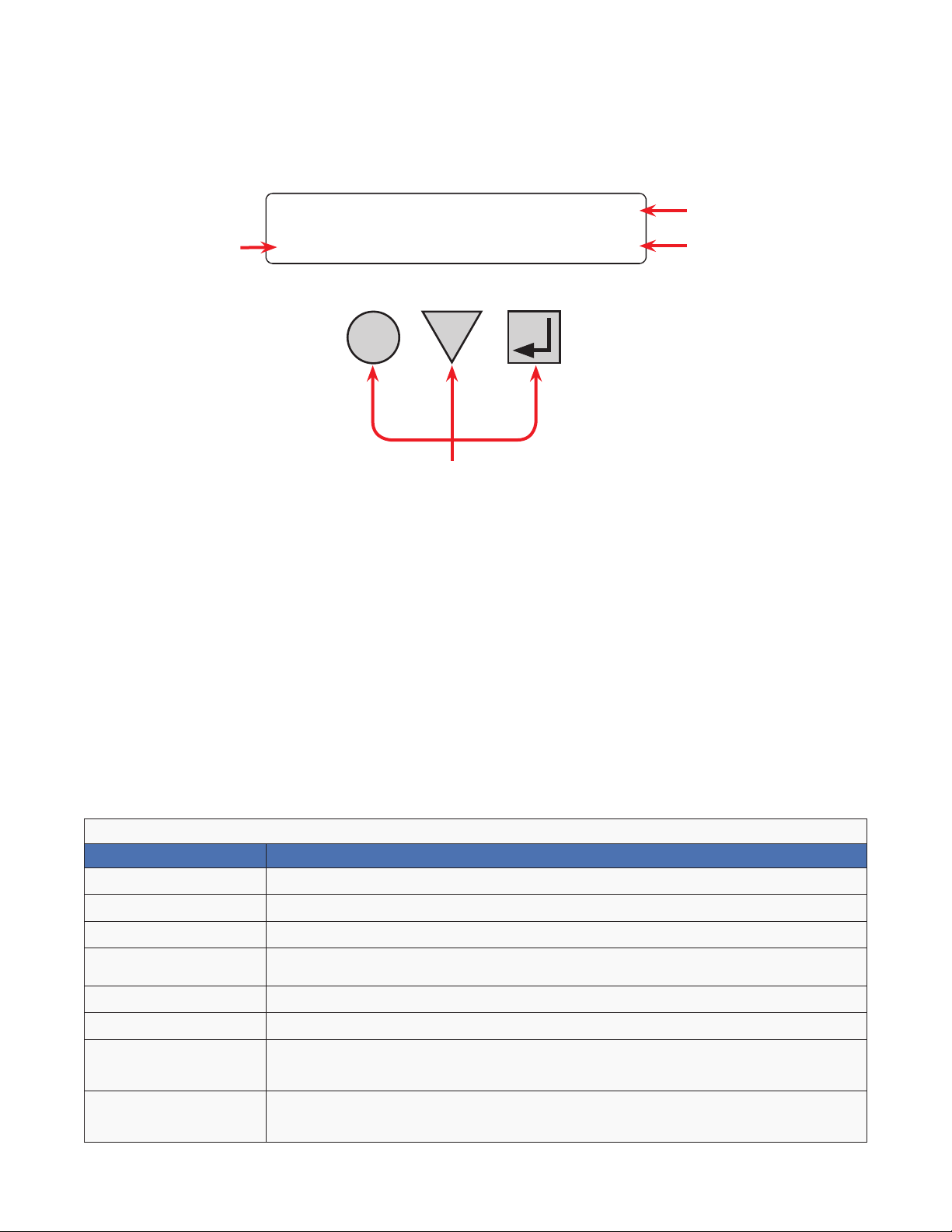
The layout of the LCD interface is shown in Figure 9.
The Alpha FXM is monitored and controlled with a series of menus and submenus.
Alpha
A
A Alpha FXM model name
Alpha FXM voltage conguration - 120 Vac or 230 Vac
B
Alpha FXM Frequency - 50 Hz or 60 Hz
Sense Type setting - Normal (N) or Generator (G); see Sense Type in Table B
C Present operating mode - (LINE mode shown) See Figure 10.
Control buttons:
SELECT - Pressing SELECT moves you down 1 level in the menu tree (Table C) or
accepts a change when programming.
D
SCROLL - Pressing SCROLL moves you through the submenus (Table C) or toggles
between choices when programming.
CANCEL - Pressing CANCEL moves you up one level in the menu tree (Table C).
FXM 2000
CANCEL
SCROLL
D
120/60/N
LINE
SELECT
B
C
Figure 9 — LCD Control Panel Logo Screen
The Alpha FXM operating mode automatically changes as a result of changes in the line or the Alpha FXM operating mode. (The LCD panel automatically updates to reflect the new mode. See Table A and also "Table V —
Boost/Buck/Line Transfer Thresholds" on page 82.
Table A — UPS Operating Modes
LCD display Description
SHUTDOWN The Alpha FXM inverter is switched off. Line power is disconnected from the load.
LINE The Alpha FXM is switched on. Line power is provided to the load.
BOOST1 OR BOOST2 The Alpha FXM transformer is raising line voltage without using the batteries. AVR is enabled.
BUCK1 OR BUCK2
INVERTER The Alpha FXM is providing backup battery power to the load.
RETRAN
STANDBY
BYPASS
The Alpha FXM transformer is lowering line voltage without using the batteries. AVR is
enabled.
The Alpha FXM is transferring from INVERTER mode to Line mode.
The Alpha FXM is switched on and waiting for the line power to qualify or the user to clear
some faults.
CAUTION: Do not touch the AC output terminals, which may still be energized.
This mode is manually set with the Control Menu. See Figure 11, “Control Menu, BYPASS”.
This locks the unit into line mode and turns off the battery charger so the unit can work with a
manual break-before-make bypass switch.
017-230-B4 Rev B
21
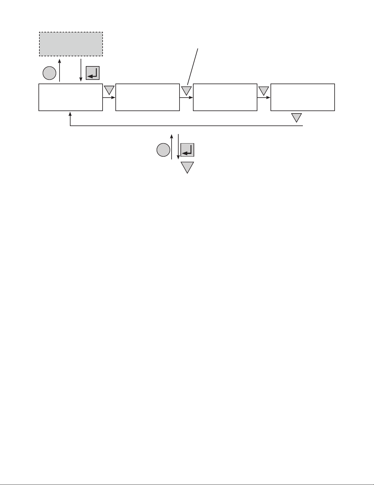
CANCEL
Logo Screen
(Figure 9)
SELECT
Starting at the Logo
Screen, press the SELECT
button to go down one level.
Press the SCROLL button to move between
the menus. The SCROLL button moves only in one
direction, so if you overshoot, you have to go all the way
around the menu tree again.
Control Menu
(Tabl e B)
System Status Menu
SCROLL
Alarm and Fault
(Tabl e C)
CANCEL
SCROLL
SELECT
Menus (If Active)
(Tabl e P and Tab le Q)
Press the SELECT button to enter the submenu.
Then press the SCROLL button to cycle through the
submenu items. The SCROLL button moves only in
one direction, so if you overshoot, you have to go all
SCROLL
Figure 10 — LCD Menu Structure
the way around the submenu again.
SCROLL
Event Status Menu
22
017-230-B4 Rev B

The CONTROL MENU
(Table B) lets you
control, program and
adjust the Alpha FXM
for connection to traffic
intersection equipment
or other applications.
You can control the:
• INVERTER Enable/
Disable
• INVERTER On/Off
• LVD DSCNNCT
• LVD CONNECT
• BYPASS
• BATT TEST
• BT TS DOD
• AUTO TEST
• SHUTDOWN
• SHUTDOWN AC
• SHUTDOWN DC
• SENSE TYPE
• FUNC MODE
• VOLTAGE
• AUTO FREQ
• FREQUENCY
• QUAL TIME
• INVERTER CUTOFF
Enable/Disable
• INVERTER CUTOFF
(voltage)
• CHARGER
• BATT FLOAT
• CHGR CUR
• BATT COMP
• DATE FRMT
• CLOCK FRMT
• INV RECORD
• RELAY TEMP
• TEMP DISP
• DAYLIGHT
• CONFIGURE IP
The SYSTEM STATUS
menu (Table C) lets you
measure various inputs,
outputs and other
values. The available
measurements are:
• VIN
• VOUT
• IOUT AC
• BATT TEMP
• FREQ IN
• OUTPUT PWR
• BATT VOLT
• CHGR CUR
• DATE
• TIME
• INV COUNT
• INV TIMER
• BUCK/BOOST
• SHED TIMER 1, 2
OR 3
• MAC Address
• IP Address
• kWh
• Remain Tm
• Serial Number
• VERSION
The ALARM and FAULT
menus in the Troubleshooting section are
invisible and disabled
until the Alpha FXM has
a malfunction.
When the front panel
alarm LED is on or
flashing, press SELECT.
One of the malfunctions
listed in Table R and
Table S will appear
on the LCD. Press the
SCROLL button to
see if more than one
malfunction is present.
Fix the malfunction.
Press the SELECT
button to clear the
malfunction from the
screen.
If the malfunction is
fixed, the malfunction
is cleared from the
LCD. If it isn’t fixed, it
will reappear on the
screen.
The EVENT STATUS
menu displays the last
200 Alpha FXM events
on the LCD.
Press the SELECT
button to access the
menu. Press SELECT
and then the SCROLL
button to scroll through
the events. To see what
a specific event was,
press the SELECT button. Press the SCROLL
button to see what
malfunction triggered
the event.
017-230-B4 Rev B
Figure 11 — LCD Menu Tree
23

6.2.1 The LCD Control Menu
The control menu (Table B) lets you operate the Alpha FXM or program it to suit your operating conditions.
Procedure
1. From the Logo screen go to the Control menu.
2. Press the SELECT button to enter the submenu (Table B).
3. Press the SCROLL button to move between items in the submenu.
4. When you have reached the item you want to change, press the SELECT button. The item chosen is blinking.
5. To toggle between the choices, press the SCROLL button. Stop when you reach the choice you want.
6. To make the change, press the SELECT button. The blinking stops.
Table B — Control Menu
LCD display Meaning Description
INVERTER
INVERTER
LVD DSCNNCT Battery voltage value at which the LVD congured relay should open
LVD CONNECT Battery voltage value at which the LVD congured relay should close
BYPASS Inverter Bypass
Inverter
(Enabled/
Disabled)
Inverter (On/
Off)
When Disable is selected and AC is lost, the FXM will be in Standby mode. The
inverter cannot be started through the Inverter On/Off menu,
When Enable is selected and AC is lost, the FXM will be in Inverter mode. Turning
inverter on/off manually will work.
When inverter mode is set to ON, the Alpha FXM provides backup battery power
to the load. This mode of operation is normally activated automatically when line
power becomes unavailable, or the line power is not qualied. You can also put
the Alpha FXM into this mode during initial startup in the absence of line power or
because of unqualied line power.
This function can only be switched on when the Alpha FXM is in Line mode. When
switched on, it locks the Alpha FXM into the Line mode, switches off the battery
charger and makes the output voltage equal to the input voltage.
Used when:
• Replacing the batteries.
OR:
• To allow the use of a break-before-make manual bypass switch so the
Alpha FXM can be shut off for maintenance or replacement without interrupting
power to the load.
Available when CHARGER on the Control Menu is set to Standard method.
BATT TEST Battery Test
BT TS DOD
AUTO TEST Automatic Test
SHUTDOWN
SHUTDOWN AC
SHUTDOWN DC
24
Battery Test
Depth-ofDischarge
Shutdown AC
and DC (On/
Off)
Shutdown AC
(On/Off)
Shutdown DC
(On/Off)
Starts the battery test, which uses depth-of-discharge setting, the battery capacity,
Peukert number, and open-circuit voltage. This setting can be adjusted using BT TS
DOD menu. A battery test is also performed during the self test.
Available when CHARGER on the Control Menu is set to Standard method.
Sets the desired battery test depth-of-discharge to a value between 0 and 100%.
Make sure that the set time duration is shorter than the max back up time of your
battery bank. Otherwise, you will drain the battery and trigger a fault – Batt Volt Low.
The default value is set to 20% DoD.
Available when CHARGER on the Control Menu is set to Standard method.
If the GUI periodic self test is enabled, this starts the test when it is scheduled to
take place.
When this function is switched On, the Alpha FXM inverter is shut off. Neither Line
nor Inverter power is supplied to the load. If a dry contact was used as a LVD, the
LVD will open.
When this function is switched On, the Alpha FXM inverter is shut off. Neither Line
nor Inverter power is supplied to the load.
When this function is switched On, the LVD congured relay will be de-energized.
Applies when ANY programmable dry contact is programmed to be the Low Voltage
Disconnect indicator. See "UPS Maintenance > Relay & Load Shed" on page 41.
When the function is switched from On to Off, a 10 second delay occurs before the
LVD congured relay is re-energized.
017-230-B4 Rev B

Table B — Control Menu
LCD display Meaning Description
This function can only be used when the Alpha FXM is in Standby or Shutdown
mode (Table A).
SENSE TYPE Sense Type
FUNC MODE Functional
VOLTAGE Voltage
AUTO FREQ Automatic
FREQUENCY Frequency
QUAL TIME
INV CUTOFF
INV CUTOFF
CHARGER
BATT FLOAT
BATT COMP
DATE FRMT
CLOCK FRMT
INV RECORD
CHGR CUR Charger current
Mode
Frequency
Detection
Line qualify
time
Inverter Cutoff
(Enabled/
Disabled)
Inverter Cutoff
Threshold
(Voltage)
Battery
charging
options
Battery
charging oat
options
Battery
temperature
compensation
Date Format
Selection
Clock display
format option
Inverter record
clear
Normal: The Alpha FXM can operate successfully with most line conditions.
OR:
Generator: This setting increases noise tolerance so the uctuations created by
a generator are acceptable. (A noisy line can cause the Alpha FXM to constantly
switch between inverter and line modes.)
The Functional mode can be changed when the Alpha FXM is in any mode (Table C
and "Table V — Boost/Buck/Line Transfer Thresholds" on page 82).
Automatic Voltage Regulation (AVR): Buck and boost modes are active.
OR:
Quality: Buck and boost modes are switched off; the input voltage is the Alpha FXM
output voltage.
Sets the Alpha FXM output voltage setting to one of the voltages specied in
"Specications" on page 80. Changing the voltage setting from factory default
should be done by a qualied technician acting under the instructions of Alpha
Technical Support (1 888 462 7487). Failure to contact Alpha Technologies before
performing this procedure could void your warranty.
Enable (default) allows the unit to detect and automatically congure the AC input
frequency (50Hz or 60Hz).
In cases where the AC input frequency can be out of range for long periods,
Disable prevents the unit from switching back and forth between 50Hz and 60Hz.
The frequency can only be changed when the Alpha FXM is in Standby mode—to
50 Hz or 60 Hz. This change should ONLY be done by a qualied technician acting
under the instructions of Alpha Technical Support (1 888 462 7487). Failure to
contact Alpha Technologies before doing this procedure could void your warranty.
Set how long it takes for the Alpha FXM to return to Line mode after the line has
become requalied to make sure the line is stable. The factory default setting
is 3 seconds. User adjustable in increments of 1 sec until 1 minute, and then in
increments of 1 minute to 15 minutes max.
When Disable is selected the default FXM inverter cutoff threshold is used.
When Enable is selected the user congured inverter cutoff threshold voltage is
used.
Denes the point where the unit will switch from Inverter to Standby when the
battery is considered to be low or in order to preserve the battery. See "UPS
Maintenance > Inverter" on page 40.
When Standard charger is selected, set BATT FLOAT to AUTO or Constant.
When Bulk charger is selected, set MAX VOLT and FLOAT VOLT. See section 6.2.2
When BATT FLOAT is set to Constant, the default max charge voltage is 54.6V
and oat is 54.2V, both at 25°C. Temperature compensation will be active
When BATT FLOAT is set to AUTO, the oat voltage is set to 1.8V below the max
charge voltage. The default max charge voltage is 54.6V and default oat is 52.8V,
both at 25°C
Sets the battery temperature compensation to match the batteries you are using. It
can be set from 0 to -6 mV/°C/Cell in increments of 0.5. The factory default setting
is -5 mV/°C/Cell.
Toggles the Alpha FXM date format between YY-MM-DD, MM-DD-YY, DD-MM-YY
YYYY-MM-DD, MM-DD-YYYY, DD-MM-YYYY, YY-TXT-DD, TXT-DD-YY, DD-TXTYY, YYYY-TXT-DD, TXT-DD-YYYY, DD-TXT-YYYY, YYYY-DD-TXT, YY-DD-TXT,
YYYY-DD-MM, YY-DD-MM. The factory default setting is MM-DD-YY.
Format to display time information: in 24 hour clock format or 12 hour clock (AM/
PM).
Clears the inverter counter and timer from the LCD system status menu.
Charging current can be set to 0A or any value between 2 and maximum in
increments of 1A, where maximum = 15A for FXM1100/FXM2000 and 10A for
FXM650. (Charging current cannot be set to 1A).
017-230-B4 Rev B
When charging current is set to 0A, the charger will stop charging.
25
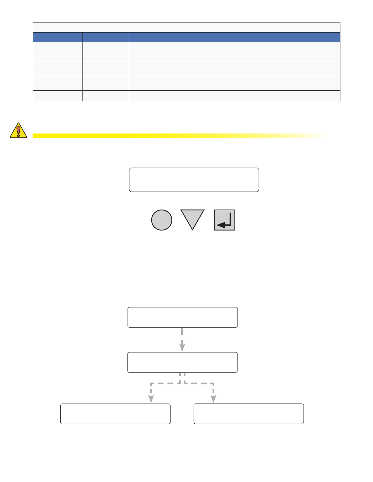
Table B — Control Menu
LCD display Meaning Description
RELAY TEMP
TEMP DISP
DAYLIGHT
CONFIGURE IP FXM IP Congure the FXM IP address
Relay
temperature
Temperature
display format
Daylight saving
option
Temperature setting to activate the specied dry contact. The congured dry contact
will activate when the set battery temperature is reached. Setting range: 20ºC to
55ºC in increments of 5ºC.
The temperature can be displayed in Celsius or Fahrenheit.
Switch ON this option to activate Daylight Saving time.
6.2.2 Battery Charging Options
CAUTION!
The adjustments to the charge algorithm must be made only by qualied personnel,
who understand the different charging modes and their suitability to the battery
chemistry.
Alpha
120/60/N
FXM2000 STANDBY
CANCEL
SCROLL
Standard Battery Charging
For more information on standard battery charging, refer to the web GUI description "UPS Maintenance > Battery"
on page 38.
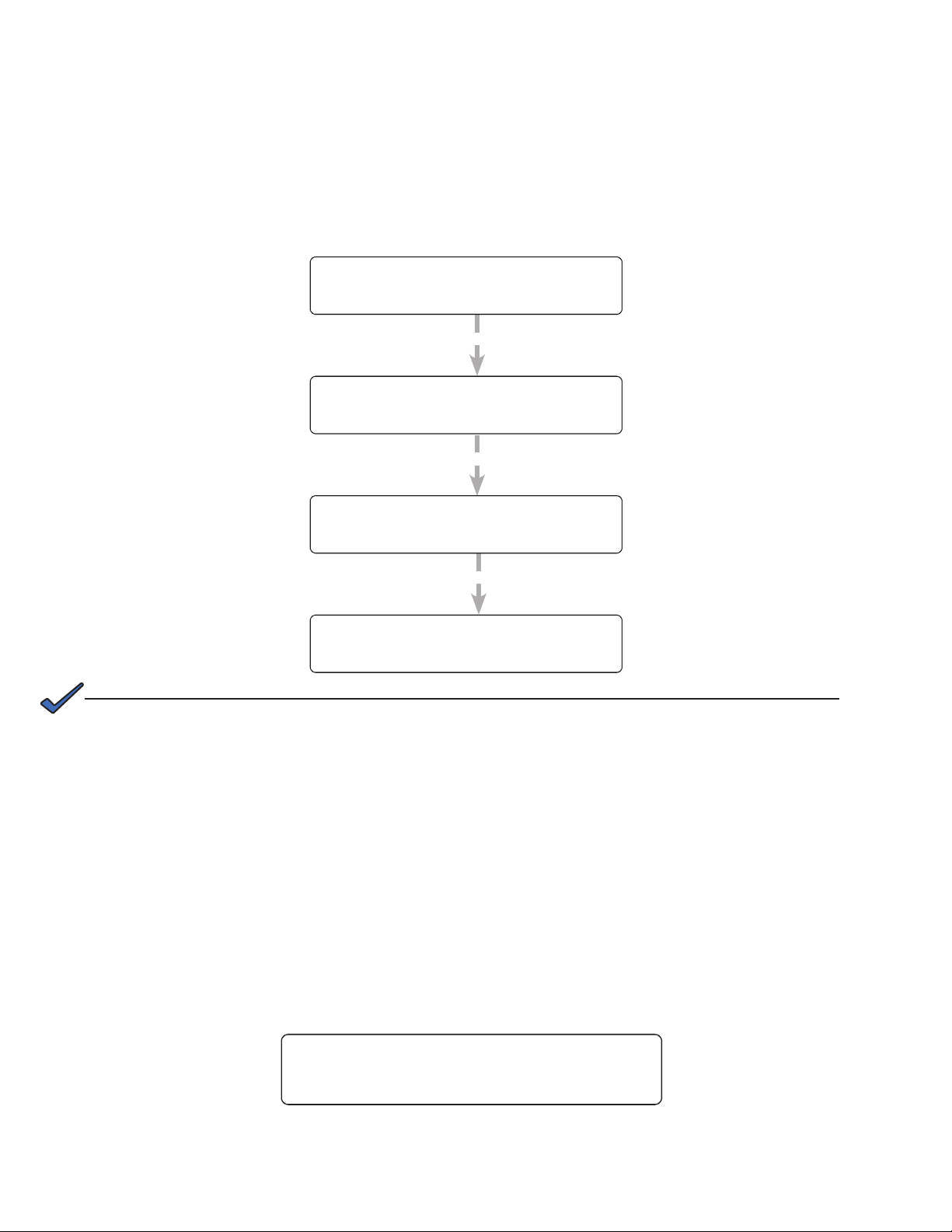
1. Put the unit in STANDBY mode before starting this procedure.
2. Use a combination of the SCROLL and SELECT keys on the control panel interface to select
CHARGER in the Control menu.
3. Select Standard to charge the batteries in AUTO or Constant mode.
CONTROL
MENUS
SELECT
120/60/N
STANDBY
BATT FLOAT
Constant
When BATT FLOAT is set to Constant, the default max
charge voltage is 54.6V and float is 54.2V, both at 25°C.
Temperature compensation will be active.
120/60/N
STANDBY
26
CHARGER
Standard
120/60/N
STANDBY
BATT FLOAT
AUTO
When BATT FLOAT is set to AUTO, the float voltage is set to
1.8V below the max charge voltage. The default max charge
voltage is 54.6V and default float is 52.8V, both at 25°C.
120/60/N
STANDBY
017-230-B4 Rev B
Bulk Battery Charging
Selecting Bulk allows programming of the max voltage and the float voltage. For more information on bulk battery
charging, refer to the web GUI description "UPS Maintenance > Battery" on page 38.
1. Put the unit in STANDBY mode before starting this procedure.
2. Use a combination of the SCROLL and SELECT keys on the control panel interface to select
CHARGER in the Control menu.
3. Select Bulk to set the max charge voltage and float voltage for charging the batteries (selectable in 0.1V
increments).
CONTROL
MENUS
CHARGER
Bulk
Selecting Bulk allows
programming of the
max charge voltage
and the float voltage.
MAX VOLT
53.5V
FLOAT VOLT
52.5V
NOTE:
Temperature compensation defaults to 0 mv/ °C/ cell in this mode, but can be changed
to non-zero values.
120/60/N
STANDBY
120/60/N
STANDBY
120/60/N
STANDBY
120/60/N
STANDBY
Selectable in 0.1V steps: from
52 to 56V. (Default is 53.5V)
Selectable in 0.1V steps: from
52V to less than or equal to max
charge voltage. (Default is 53.5V)
If you set the max charging voltage to a value lower than currently set oat voltage, oat
voltage will be automatically adjusted to be equal to the new max charging voltage.
6.2.3 Controlling the external fan by temperature triggered dry contact
The Temperature trigger has a user configurable range of +20°C to +55°C (68 to 131 °F). When the battery
temperature (monitored by the Battery Temperature Probe) reaches the threshold, the assigned relay closes and
turns on the external fan.
Procedure
From the Logo screen, navigate to Control Menu > RELAY TEM P. Press the SELECT button and the current
temperature display will start flashing. Use the Scroll button to change the temperature in 5°C increments. Press
SELECT to accept the changes or CANCEL to abort.
RELAY TEMP
55
Dry contact functions are not programmable through the LCD. Use the Web GUI or HyperTerminal instead.
017-230-B4 Rev B
120/60/N
LINE
27
Loading...