


CTE-1200 AT

Celltron Essential
™
Stationary Battery Strings Analyzer
CTE-1200 AT; CTE-2200 AT;
CTE-3200 AT
INSTRUCTION MANUAL


i
Table of Contents
Introduction ..................................................................................................... 1
Safety instructions .................................................................................................1
Important.............................................................................................................1
Guidelines ...........................................................................................................1
About the analyzer .................................................................................................1
Terminology ........................................................................................................1
Chapter 1: Description ................................................................................... 2
Specications .........................................................................................................2
Measurements ....................................................................................................2
Test capability ..................................................................................................... 2
Test range ...........................................................................................................2
Data storage .......................................................................................................2
Parts of the analyzer .............................................................................................3
Panels .................................................................................................................3
Parts on the panels .............................................................................................4
Menu options ..........................................................................................................4
Menus .................................................................................................................4
Main MENU ........................................................................................................4
1. SET PARAMETERS menu .............................................................................5
2. TEST BATTERY option ...................................................................................6
3. VIEW PARAMETERS menu ........................................................................... 6
4. PRINT RESULTS option .................................................................................6
5. VIEW RESULTS menu ...................................................................................6
6. EXPORT DATA option ....................................................................................7
7. CHANGE REF. option .....................................................................................7
8. UTILITIES menu .............................................................................................7
Chapter 2: Pre-testing .................................................................................... 9
Determining a reference value .............................................................................. 9
Reference values ................................................................................................9
Options ...............................................................................................................9
Testing a sample of jars .................................................................................... 10
Using the average in SITE SUMMARY ............................................................10

ii
Setting options in the UTILITIES menu .............................................................. 11
Introduction ....................................................................................................... 11
Options ............................................................................................................. 11
Accessing the UTILITIES menu........................................................................ 11
Setting the language (A. LANGUAGE) .............................................................12
Setting the date and time (B. DATE & TIME) ....................................................12
Setting the date and time format (C. SET DATE FORMAT) .............................12
Editing the site name (D. EDIT SITE NAME) .................................................... 12
Setting percentages for warnings and failings (E. SET WARN/FAIL %) ...........13
Setting the low voltage value (F. LOW VOLTS) ................................................13
Setting auto or manual start (G. AUTO START) ...............................................13
Adjusting the screen contrast (H. CONTRAST)................................................14
Return to the main MENU (I. MAIN MENU) ...................................................... 14
Setting values in the SET PARAMETERS menu ................................................14
Introduction .......................................................................................................14
Options .............................................................................................................14
Accessing the SET PARAMETERS menu ........................................................ 15
Selecting 1. SYSTEM VOLTS ..........................................................................15
Selecting 2. JARS ONLY or JARS AND STRAPS as a test point ....................15
Setting the site temperature (3. TEMP:) ...........................................................16
Setting the reference value (4. REF:) ...............................................................16
Setting the number of volts per jar (5. VOLTS/JAR) ......................................... 16
Selecting the battery to test (6. SELECT BATTERY)........................................17
Selecting the TEST BATTERY option ...............................................................18
Editing a vendor name (EDIT VENDOR NAME) ..............................................18
Adding or editing a model name (EDIT MODEL NAME) ..................................18
Chapter 3: Testing ........................................................................................ 19
Labeling jars and straps ...................................................................................... 19
Recommendations ...............................................................................................20
Recording jar information..................................................................................20
Labels for jars and straps .................................................................................20
Preparing to test ................................................................................................... 20
Introduction .......................................................................................................20
Requirements ...................................................................................................20
Selecting a cable ..............................................................................................20
Attaching the cable to the analyzer...................................................................21

iii
Determining a test pattern ................................................................................... 22
Introduction .......................................................................................................22
Setting the 2. TEST BATTERY option ..............................................................22
Attaching the cables ............................................................................................23
Introduction .......................................................................................................23
General rules ....................................................................................................23
Attaching the cable to jar posts.........................................................................23
Attaching the cable to a strap ...........................................................................24
Retesting jar posts or straps ..............................................................................25
Introduction .......................................................................................................25
Retesting after testing the jar post or strap .......................................................25
Retesting after testing the site ..........................................................................25
Chapter 4: Test Results ................................................................................ 27
Viewing test results .............................................................................................27
Introduction .......................................................................................................27
Viewing test results ...........................................................................................27
Interpreting test results .......................................................................................28
SITE SUMMARY ..............................................................................................28
REVIEW DATA SET .......................................................................................... 28
Using the percentages of the reference value ..................................................28
Archiving test results ..........................................................................................29
Advantages of archiving ...................................................................................29
Printing test results ...........................................................................................29
Downloading Test Results ................................................................................30
Chapter 5: Troubleshooting ......................................................................... 31
Screen does not light during testing .................................................................. 31
Possible causes ................................................................................................31
Replacing the analyzer battery .........................................................................31
Replacing the fuse ............................................................................................31
Probe tip is bent or stops retracting ..................................................................32
Replacing a probe tip ........................................................................................32
Chapter 6: Specications ............................................................................ 33

iv
Guide to Tables and Figures
Table 1. Parts of the panels ...........................................................................4
Table 2. SET PARAMETERS menu options ..................................................5
Table 3. VIEW RESULTS menu options ........................................................6
Table 4. UTILITIES menu options .................................................................8
Table 5. Advantages of cables.....................................................................21
Table 6. Strength of the site.........................................................................29
Figure 1. Front, back, and top panels............................................................3
Figure 2. Test pattern and labels of jars and straps on 2 strings .................19
Figure 3. Attaching the cable to the analyzer ..............................................21
Figure 4. Connection between positive and negative posts ........................22
Figure 5. Attaching the cable to jar posts ....................................................23
Figure 6. Attaching the cable to a strap .......................................................25
Figure 7. REVIEW DATA SET values ......................................................... 28
Figure 8. Top of Analyzer .............................................................................29
Figure 9. Sample of a printout ....................................................................30

1
Introduction
This manual provides descriptions and operating instructions for the Midtronics Celltron Essential
CTE-1200 AT, CTE-2200 AT and CTE-3200 AT stationary battery string analyzers. It helps you
understand the parts of the analyzer and how to use it to test batteries.
Safety instructions
Important
Read the instructions below before you operate the analyzer.
Guidelines
To avoid electric shock when testing batteries, follow your company safety practices and these guidelines:
• Wear safety glasses or a face shield.
• Wear protective rubber gloves.
• Wear a protective apron or shop coat.
• Perform only service work for which you have been trained.
• Do not disconnect battery cables from power systems without authorization
for the length of time needed to complete testing.
• Avoid placing yourself into a circuit.
• While in contact with the battery, avoid contact with frame racks and
adjacent hardware that may be grounded.
About the analyzer
Terminology
The analyzer and manual use the term “jar,” an international term for “battery.”
A string is a series of jars connected together by straps to provide power as a whole.
A site is a location with batteries to be tested. A site can consist of one or more strings.

2
Chapter 1: Description
The Celltron Essential is a stationary battery string analyzer that measures the conductance and
voltage of individual strings of three-cell (6 V) and six-cell (12 V) stationary, lead-acid jars to help
identify those that:
• Are good
• Are serviceable
• Need to be replaced
Specications
Measurements
The analyzer measures the status of a jar in voltage and conductance values. It displays conductance
values in siemens (S). Ampere hours (Ah) are a typical measurement of jar capacity; however, they
are difcult to measure without knowing the load to which the jars supply power.
Midtronics recommends that you use a reference value to compare the conductance value to the test
results. A reference value is a typical conductance value for the type of jars you are testing. For more
information about determining a reference value, refer to “Chapter 2: Pre-testing.”
Test capability
The analyzer tests jars that are providing power to a load (in-service) or those that are not providing
power (not in-service).
Test range
The analyzer has an operating range of 0 to 9999 S. This range includes jars that have about 5 to 2400
Ah of reserve capacity.
Data storage
The analyzer has 12 site partitions for storing data. Each site partition holds data for 4 battery strings
within the site.
3
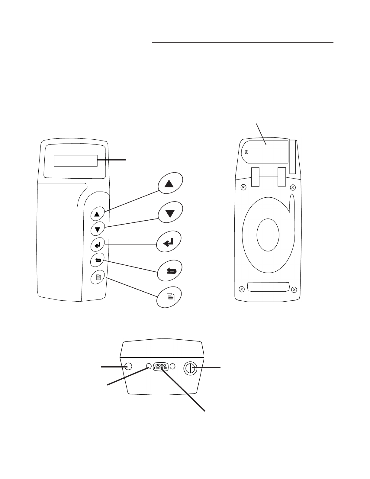
Parts of the analyzer
Panels
The panels allow you to use, care for, and hook up the analyzer. Figure 1 displays the front, back, and
top panels of the analyzer and their parts.
Top
Infrared light
Screw holes
Cable port
Fuse holder
Figure 1. Front, back, and top panels
Screen
Front
D
O
W
N
E
N
T
E
R
M
E
N
U
R
E
T
E
S
T
U
P
UP
DOWN
ENTER
RETEST
MENU
Back
Battery door
D
O
W
N
E
N
T
E
R
M
E
N
U
R
E
T
E
S
T
U
P

4
Parts on the panels
Table 1 describes the parts of the panels.
Table 1. Parts of the panels
Part Description
Screen Displays menus, options, and test results.
UP Enables you to scroll up in a menu or number selections.
DOWN Enables you to scroll down in a menu or number selections.
ENTER Moves to the option you select or enters number selections.
RETEST Opens a menu with options to retest the jar or strap you just tested.
MENU Turns the analyzer on and off.
Battery door Covers the analyzer battery compartment.
Infrared light Transfers data from the analyzer to the printer, or to another IR receiver.
Screw holes Enables screws to anchor the cable to the analyzer.
Cable port Connects the probes or clamps to the analyzer.
Fuse holder Houses the fuse for the analyzer.
Menu options
Menus
The analyzer displays menus on the screen from which you can select options before, during, and
after testing. You can access options from the main MENU.
Main MENU
To access the main MENU, press and hold the MENU button. The main MENU displays these options:
1. SET PARAMETERS
2. TEST BATTERY
3. VIEW PARAMETERS
4. PRINT RESULTS
5. VIEW RESULTS
6. EXPORT DATA
7. CHANGE REF.
8. UTILITIES
NOTE: If the analyzer was last used while
in UTILITIES mode, that will be the rst
menu displayed when you turn the unit
back on. To return to the main MENU,
scroll to I. MAIN MENU and press ENTER.

5
Note: All main MENU choices (except UTILITIES)
lead to a list of sites, from 01. to 12.
Option 13. ALL SITES (available for 1, 4, 6 and 7 only--
SET PARAMETERS, PRINT, EXPORT, or CHANGE REF)
allows you to apply the option to all 12 sites.
1. SET PARAMETERS menu
The SET PARAMETERS menu allows you to set values for a site so it is ready to test. If you do not, the
analyzer tests the string against the last setting used.
The screen displays these options, along with their currently specied values, as described in Table 2:
1. SYSTEM VOLTS 36V
2. JARS ONLY
3. TEMP 25°C
4. REF 1000 S
5. VOLTS/JAR 12
6. SELECT BATTERY
7. MAIN MENU
Table 2. SET PARAMETERS menu options
Option Description
SYSTEM VOLTAGE The nominal number of volts in the system (36 or 48V). The default is 36 V.
JARS ONLY, or
JARS & STRAPS
• Jars (JARS ONLY)
• Cells and inter-cell connections of the site (JARS & STRAPS)
The default is JARS ONLY.
TEMP
Temperature of the site. The analyzer compensates for temperature since
conductance measurements change with jar temperature. The analyzer
measures an absolute conductance value. However, it uses the TEMP
value to adjust the reference value you enter in REF. The percent is
compensated to 25 °C (77 °F). Compensation is adjusted at 0.7% per
degree Celsius between 0 °C and 35 °C.
The default is 25 °C (77 °F).
REF
Reference value in siemens. For more information about reference values,
refer to “Determining a reference value.” The default is 1000 S.
VOLTS/JAR Number of volts for a battery (6 or 12 V). The default is 12 V.
SELECT BATTERY Choose the battery you wish to test.
MAIN MENU Returns to the top menu.
A full description and instructions for the SET PARAMETERS menu is provided in “Chapter 2.
Setting Parameters.”
01. SITE 01
02. SITE 02
03. SITE 03
SELECT SITE

6
2. TEST BATTERY option
The TEST BATTERY option allows you to test a jar after you connect the cables to the jar posts. If you
do not have the cables connected to the jar posts before you select TEST BATTERY, the screen prompts
you to connect to a jar.
3. VIEW PARAMETERS menu
The VIEW PARAMETERS menu displays the values you set up for a site under the SET PARAMETERS
menu. This menu allows you to view the parameters only. For descriptions of these options, refer to
“SET PARAMETERS menu.”
4. PRINT RESULTS option
The PRINT RESULTS option allows you to print test results for a site you tested.
5. VIEW RESULTS menu
The VIEW RESULTS option allows you to view test results
for a site you tested. When you select the site, the screen
displays the following options, described in Table 3:
Table 3. VIEW RESULTS menu options
Option Description
SITE
SUMMARY
Lists these values as a summary of the site you tested:
• AVG. % — Average percentage of the reference value.
• AVG. SIEMENS: — Average conductance value.
• TOTAL JARS: — Total number of jars you tested in the site.
• LOW: — Jar number with the lowest percentage of the reference value.
• HIGH: — Jar number with the highest percentage of the reference value.
• SITE — Average percentage of the site’s strings as compared to the jar in
the site with the highest conductance value.
REVIEW DATA
SET
Gives the following information for each Jar and Strap test:
• voltage
• conductance value
• number of the jar or strap
• percent of the reference value
• warning and failure indicators
The analyzer keeps the test results for a site until you erase the data.
Helpful hint: The RETEST button provides a shortcut to the REVIEW DATA SET screen.
1. SITE SUMMARY
2. REVIEW DATA SET
3. MAIN MENU
03.
SITE 03
 Loading...