


Technical Manual
CE-3x2 5K-T 48Vdc Telecom Generator PN-6x-T 7.5kW 48Vdc Telecom Generator
Effective: May 2008
Alpha Technologies

PowerAlpha Technologies 


 ®
®

TM
CE-3x2 5K-T 48Vdc Telecom Generator PN-6x-T 7.5kW 48Vdc Telecom Generator Technical Manual
042-288-B0-001, Rev. A
Effective Date: May 2008
Copyright © 2008
Alpha Technologies, Inc.
member of The  GroupTM
NOTE:
Photographs contained in this manual are for illustrative purposes only. These photographs may not match your installation.
NOTE:
Operator is cautioned to review the drawings and illustrations contained in this manual before proceeding. If there are questions regarding the safe operation of this powering system, please contact Alpha Technologies or your nearest Alpha representative.
NOTE:
Alpha shall not be held liable for any damage or injury involving its enclosures, power supplies, generators, batteries, or other hardware if used or operated in any manner or subject to any condition not consistent with its intended purpose, or is installed or operated in an unapproved manner, or improperly maintained.
Contacting Alpha Technologies: www.alpha.com
or
For general product information and customer service (7 AM to 5 PM, Pacific Time), call
1-800-863-3930,
For complete technical support, call
1-800-863-3364
7 AM to 5 PM, Pacific Time or 24/7 emergency support
3
Table of Contents
Safety Notes |
.......................................................................................................................... |
|
8 |
|
1.0 |
System ......................................................................................................Overview |
13 |
||
|
1.1 .............................................................................. |
PN - 6x - T System Diagram |
14 |
|
|
1.2 ........................................................................ |
CE3x2 5kW System Diagram |
15 |
|
|
1.3 .............................................................. |
Natural Gas System Block Diagram |
16 |
|
|
1.4 ......................................................... |
Liquid Propane System Block Diagram |
17 |
|
|
1.5 ................................................................................................. |
Speci fi cations |
18 |
|
2.0 |
Site Preparation........................................................................................................ |
21 |
||
|
2.1 ........................................................................................ |
Site Considerations |
21 |
|
|
2.2 ........................................................................................................ |
Acoustics |
21 |
|
|
2.3 .......................................................................... |
Enclosure Impact Protection |
23 |
|
|
2.4 ................................................................. |
Natural Gas Meter Con fi gurations |
25 |
|
|
2.5 ................................................................................ |
Liquid Propane Systems |
27 |
|
|
2.6 ........................................................ |
Grounding Requirements, CE - 3x2 5K - T |
28 |
|
|
2.7 ..................................................... |
Grounding Requirements, PN - 6xT 7.5kW |
29 |
|
3.0 |
Installation................................................................................................................. |
|
30 |
|
|
3.1 ........................ |
Installing the CE - 3x2 5K - T or PN - 6x - T 7.5kW Pad Template |
30 |
|
|
3.2 ............................................................................... |
Installation, CE - 3x2 5K - T |
33 |
|
|
.............................................. |
3.2.1 CE - 3x2 5K - T Transportation and Lifting |
34 |
|
|
................................................... |
3.2.2 Enclosure Installation, CE - 3x2 5K - T |
36 |
|
|
3.3 ........................................................................... |
PN - 6x - T 7.5kW Installation |
37 |
|
|
|
3.3.1 PN - 6x - T 7.5kW Transportation and Lifting, ......................................... 38 |
||
|
.............................. |
3.3.2 Enclosure Installation Procedure, PN - 6x - T 7.5kW |
40 |
|
|
3.4 .............................................................. |
Enclosure Grounding, CE - 3x2 5K - T |
41 |
|
|
3.5 ........................................................... |
Enclosure Grounding, PN - 6x - T 7.5kW |
42 |
|
|
3.6 .............................................. |
Natural Gas Utility Fuel Hookup, CE - 3x2 5K - T |
43 |
|
|
3.7 .......................................... |
Natural Gas Utility Fuel Hookup, PN - 6x - T 7.5kW |
44 |
|
|
3.8 ......................................... |
Liquid Propane Utility Fuel Hookup, CE - 3x2 5K - T |
45 |
|
|
3.9 ..................................... |
Liquid Propane Utility Fuel Hookup, PN - 6x - T 7.5kW |
46 |
|
|
3.10 ......................................... |
Making the DC Output Connection, CE - 3x2 5K - T |
47 |
|
|
3.11 ...................................... |
Making the DC Output Connection, PN - 6x - T 7.5kW |
48 |
|
|
3.12 ............................................... |
Connecting the Ignition Battery, CE - 3x2 5K - T |
49 |
|
|
3.13 ........................................... |
Connecting the Ignition Battery, PN - 6x - T 7.5kW |
50 |
|
|
3.14 ................................. |
Terminal Block 2 (AC Line) Connections, CE - 3x2 5K - T |
51 |
|
|
3.15 ............................. |
Terminal Block 2 (AC Line) Connections, PN - 6x - T 7.5kW |
52 |
|
|
3.16 .............................................................................. |
Final Inspection Checklist |
53 |
|
4.0 The Engine .....................................................................................Control Module |
54 |
|||
|
4.1 ....................................................................................... |
Theory of Operation |
56 |
|
|
.................... |
4.1.1 Standby Operating Condition Less Than Three Minutes |
56 |
|
|
.................... |
4.1.2 Standby Operating Condition More Than Three Minutes |
56 |
|
|
....................................................................... |
4.1.3 |
Normal APU Shutdown |
57 |
|
.................................................................... |
4.1.4 |
Abnormal APU Shutdown |
57 |
|
4.2 .................................................................... |
ECM Operating Mode Summary |
57 |
|
|
4.3 ............................................................................................... |
LED Indicators |
58 |
|
4 |
042-288-B0-001, Rev. A |
|
4.4 |
Control Functions........................................................................................... |
59 |
|
4.5 |
Alarm Classifications...................................................................................... |
60 |
|
4.6 |
ECM Alarm Overview..................................................................................... |
62 |
|
4.7 |
Connecting the Alarm and Control Connections............................................ |
63 |
|
4.8 |
ECM DIP Switch and Fuse Configuration ...................................................... |
64 |
|
4.9 |
ECM Interface Block Diagram and Connectors ............................................. |
66 |
|
4.10 |
ECM Self-test................................................................................................. |
67 |
|
4.11 |
Maintenance Functions ................................................................................. |
68 |
5.0 |
Turn-up and Test....................................................................................................... |
69 |
|
|
5.1 |
Appearance and Condition of Components................................................... |
69 |
|
5.2 |
System Preparation ....................................................................................... |
69 |
|
5.3 |
Performing a Local APU Test ......................................................................... |
70 |
|
5.4 |
Generator System Sensor Verification........................................................... |
71 |
|
|
5.4.1 Enclosure Alarm Verification ............................................................... |
71 |
|
|
5.4.2 AC and DC Line Sense Verification .................................................... |
72 |
6.0 |
Operation.................................................................................................................. |
73 |
|
|
6.1 |
Normal Operating Condition .......................................................................... |
73 |
|
|
6.1.1 AC Line Fail......................................................................................... |
73 |
|
|
6.1.2 Low DC Bus Level............................................................................... |
73 |
|
6.2 |
Alpha Ignition Battery Charger Overview....................................................... |
74 |
7.0 |
Maintenance ............................................................................................................. |
75 |
|
|
7.1 |
Servicing the APU.......................................................................................... |
76 |
|
7.2 |
Filter Cleaning, CE-3x2 5K-T......................................................................... |
77 |
|
7.3 |
Filter Cleaning, PN-6x-T 7.5kW ..................................................................... |
78 |
|
7.4 |
Pad Shear Magnetic Switch Replacement..................................................... |
79 |
|
7.5 |
Replacing Gas Hazard Sensor ...................................................................... |
80 |
|
7.6 |
Replacing Ignition Battery Charger Module Assembly................................... |
81 |
|
7.7 |
Replacing Engine Control Module ................................................................ |
82 |
|
7.8 |
Fuel Conversion, Natural Gas to LP .............................................................. |
83 |
|
|
7.8.1 PN-6x-T Pre-regulator Removal with Low Pressure Switch Installation...... |
83 |
|
|
7.8.2 Switching the LP Port to the NG Port, PN-6x-T .................................. |
84 |
|
|
7.8.3 Switching the NG Port to the LP Port, CE-3X2 ................................... |
85 |
|
7.9 |
Maxitrol Pre-regulator Calibration .................................................................. |
86 |
8.0 |
Interconnection ......................................................................................................... |
89 |
|
|
8.1 |
Gas Hazard Alarm Interface Connector......................................................... |
89 |
|
8.2 |
Low Fuel Pressure Interface Connector ........................................................ |
89 |
|
8.3 |
Gas Solenoid Interface Connector ................................................................ |
92 |
|
8.4 |
Charger Module Control Interface Connector ............................................... |
90 |
|
8.5 |
ECM Enclosure Alarm Interface Connector ................................................... |
91 |
|
8.6 |
Inverter Battery DC Sense Interface Connector ............................................ |
91 |
|
8.7 |
Charger Control Interface Connector............................................................. |
92 |
|
8.8 |
ECM AC Line Sense 120/240V Interface....................................................... |
92 |
|
8.9 |
ECM APU Control Interface ........................................................................... |
93 |
|
8.10 |
ECM Alarm Interface...................................................................................... |
93 |
042-288-B0-001, Rev. A |
5 |
List of Figures |
|
Fig. 1-1, PN-6x-T 7.5kW Telecom Generator ...................................................................... |
13 |
Fig. 1-2, CE-3x2 5K-T Telecom Generator .......................................................................... |
13 |
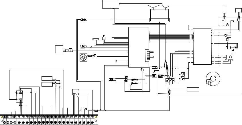
Fig. 1-3, PN-6x-T System Diagram ..................................................................................... |
14 |
Fig. 1-4, CE3x2 System Diagram........................................................................................ |
15 |
Fig. 1-5, Arrangement of Metered, Nominal Pressure (1-2psi) Natural Gas System........... |
16 |
Fig. 1-6, Excess Flow Valve ............................................................................................... |
16 |
Fig. 1-7, LP Propane Vapor Withdrawal Block Diagram...................................................... |
17 |
Fig. 2-1, Generator Sound Levels at 100% Load ................................................................ |
21 |
Fig. 2-2, Acoustical Measurements in Relation to Placement Near Residences................. |
22 |
Fig. 2-3, Vehicular Area Impact Protection for Collocated Natural Gas Meter ................... |
23 |
Fig. 2-4, Vehicular Area Impact Protection for Remote Natural Gas Meter ........................ |
24 |
Fig. 2-5, Collocated Natural Gas Meter Setup for CE-3x2 Generator ................................. |
25 |
Fig. 2-6, Collocated Natural Gas Meter Setup for PN-6x-T 7.5kW System......................... |
25 |
Fig. 2-7, Collocated CE-3x2 5K-T Generator with Remote Natural Gas Meter ................... |
26 |
Fig. 2-8, Remote Natural Gas Meter Setup for PN-6x-T 7.5kW Generator ......................... |
26 |
Fig. 2-9, Liquid Propane Setup, CE-3x2 5K-T..................................................................... |
27 |
Fig. 2-10, Liquid Propane Setup, PN-6x-T 7.5kW ............................................................... |
27 |
Fig. 2-11, Enclosure Grounding, CE-3x2 5K-T .................................................................... |
28 |
Fig. 2-12, Enclosure Grounding, PN-6x-T 7.5kW ................................................................ |
29 |
Fig. 3-1, Pad Frame Template for CE-3x2 5K-T .................................................................. |
30 |
Fig. 3-2, Pad frame and mounting template CE-3x2 5.0 kW .............................................. |
31 |
Fig. 3-3, Cross-section of Sweep Trench ............................................................................ |
32 |
Fig. 3-4, Pad Bolt Location, CE-3x2 5K-T ........................................................................... |
34 |
Fig. 3-5, Lifting Ear Attachment ........................................................................................... |
35 |
Fig. 3-6, Enclosure with Lifting Ears Installed, CE-3x2 5K-T............................................... |
36 |
Fig. 3-7, Water Intrusion Alarm (1), Pad Shear Sensor (2), and Pad Shear Magnet (3) ..... |
36 |
Fig. 3-8, PN-6x-T 7.5kW Sweep Dimensions (in inches) .................................................... |
37 |
Fig. 3-9, Pallet Bolt Locations, PN-6x-T 7.5kW ................................................................... |
38 |
Fig. 3-10, Enclosure with Lifting Ears Installed, PN-6x-T 7.5kW ......................................... |
39 |
Fig. 3-11, Installation Location of Pad Shear/Magnet Assembly ......................................... |
40 |
Fig. 3-12, Enclosure Grounding, CE-3x2 5K-T.................................................................... |
41 |
Fig. 3-13, Enclosure Grounding, PN-6x-T 7.5kW ............................................................... |
42 |
Fig. 3-14, Utility Gas Service Input, CE-3x2 5K-T ............................................................... |
43 |
Fig. 3-15, Utility Gas Service Input, PN-6x-T 7.5kW ........................................................... |
44 |
Fig. 3-16, Propane Fuel Hookup, CE-3x2 5K-T................................................................... |
45 |
Fig. 3-17, Propane Fuel Hookup, PN-6x-T 7.5kW............................................................... |
46 |
Fig, 3-18, DC Output, CE-3x2 5K-T..................................................................................... |
47 |
Fig. 3-19, DC Output Safety Shroud.................................................................................... |
48 |
Fig. 3-20, DC Output Connections, PN-6x-T 7.5kW............................................................ |
48 |
Fig. 3-21, Terminal Block 2 (TB2) Position 1, 5kW .............................................................. |
51 |
Fig. 3-22, Terminal Block 2 (TB2), PN-6x-T7.5kW .............................................................. |
52 |
6 |
042-288-B0-001, Rev. A |
Fig. 4-1, Location of Engine Control Module (ECM) ........................................................... |
54 |
Fig. 4-2 (a), ECM LED Indicators, Switches, and Interface Connections............................ |
55 |
Fig. 4-2 (b), ECM Printed Circuit Boards ............................................................................ |
55 |
Fig. 4-3, LED Indicators and Control Functions................................................................... |
59 |
Fig. 4-4, Terminal Block 1 .................................................................................................... |
63 |
Fig. 4-5, SW5 and Fuse Locations ...................................................................................... |
64 |
Fig. 4-6, SW5 Settings......................................................................................................... |
65 |
Fig. 4-7, ECM/APU Interconnection ................................................................................... |
66 |
Fig. 5-1, Generator Set Master Switch and Run/Auto/Stop (RAS) Switch .......................... |
70 |
Fig. 6-1, Ignition Battery Charger LED ................................................................................ |
74 |
Fig. 6-2, Wiring for ECM, Ignition Battery Charger, and Ignition Battery ............................. |
74 |
Fig. 7-1, Captive Fastener Location, CE-3x2 5K-T.............................................................. |
77 |
Fig. 7-2, Air Filter Removal, CE-3x2 5K-T ........................................................................... |
77 |
Fig. 7-3, Filter Replacement, PN-6x-T 7.5kW...................................................................... |
78 |
Fig. 7-4, Pad Shear Sensor................................................................................................. |
79 |
Fig. 7-5, Gas Hazard Sensor Location (Alpha P/N 744-891-20) ......................................... |
80 |
Fig. 7-6, Ignition Battery Charger ........................................................................................ |
81 |
Fig. 7-7, ECM ...................................................................................................................... |
82 |
Fig. 7-8, PN-6x-T Pre-regulator Removal............................................................................ |
83 |
Fig. 7-9, PN-6x-T Switch Assembly Installed....................................................................... |
83 |
Fig. 7-10, Load Block, PN-6x-T 7.5kW ................................................................................ |
84 |
Fig. 7-11, Changing Load Block Configuration, PN-6x-T 7.5kW ......................................... |
84 |
Fig. 7-12, Changing Load Block Configuration, CE-3x2 5K-T............................................. |
85 |
Fig. 7-13, Primary Fuel Regulator ....................................................................................... |
86 |
Fig. 7-14, Pre-regulator Calibration ..................................................................................... |
87 |
Fig. 7-15, Secondary Demand Regulator............................................................................ |
87 |
Fig. 7-16, Manometer Connection....................................................................................... |
88 |
Fig. 8-1, Gas Hazard Detector Interface Connector............................................................ |
89 |
Fig. 8-2, Low Fuel Pressure Interface Connector................................................................ |
89 |
Fig. 8-3, Gas Solenoid Interface Connector ........................................................................ |
90 |
Fig. 8-4, Charger Control Interface Connector .................................................................... |
90 |
Fig. 8-5, ECM Enclosure Alarm Interface Connector........................................................... |
91 |
Fig. 8-6, Inverter Battery DC Sense Interface Connector.................................................... |
91 |
Fig. 8-7, Charger Control Interface Connector .................................................................... |
92 |
Fig. 8-8, ECM AC Line Sense, 120/240V Interface ............................................................. |
92 |
Fig. 8-9, APU Control Interface............................................................................................ |
93 |
Fig. 8-10, ECM Connector Arrangement ............................................................................. |
93 |
042-288-B0-001, Rev. A |
7 |

Safety Notes
Review the drawings and illustrations contained in this manual before proceeding. If there are any questions regarding the safe installation or operation of the system, contact Alpha Technologies or the nearest Alpha representative. Save this document for future reference.
To reduce the risk of injury or death, and to ensure the continued safe operation of this product, the following symbols have been placed throughout this manual. Where these symbols appear, use extra care and attention.
ATTENTION:
The use of ATTENTION indicates specific regulatory/code requirements that may affect the placement of equipment and installation procedures.
NOTE:
A NOTE provides additional information to help complete a specific task or procedure.
CAUTION!
The use of CAUTION indicates safety information intended to PREVENT DAMAGE to material or equipment.
 WARNING!
A WARNING presents safety information to PREVENT INJURY OR DEATH to the technician or user.
8 |
042-288-B0-001, Rev. A |
General Safety Precautions
To avoid injury:
•This enclosure and its associated hardware must be serviced only by authorized personnel.
•Enclosure must remain locked at all times, except when authorized service personnel are present.
•Remove all conductive jewelry or personal equipment prior to servicing equipment, parts, connectors, wiring, or batteries.
•Read and follow all installation, equipment grounding, usage, and service instructions included in this manual.
•Use proper lifting techniques whenever handling enclosure, equipment, parts, or batteries.
•Batteries contain dangerous voltages, currents and corrosive material. Battery installation, maintenance, service and replacement must be performed by authorized personnel only.
•Never use uninsulated tools or other conductive materials when installing, maintaining, servicing or replacing batteries.
•Use special caution when connecting or adjusting battery cabling. An improperly connected battery cable, or unconnected battery cable, can result in arcing, fire, or possible explosion.
•A battery that shows signs of cracking, leaking or swelling must be replaced by authorized personnel immediately using a battery of identical type and rating.
•Avoid any contact with gelled or liquid emissions from a valve-regulated lead-acid (VRLA) battery. Emissions contain dilute sulfuric acid that is harmful to the skin and eyes. Emissions are electrolytic, and are electrically conductive and are corrosive. Follow the Chemical Hazards notes if contact occurs.
•Do not smoke or introduce sparks in the vicinity of the batteries or natural gas/propane connections.
•Under certain overcharging conditions, lead-acid batteries can vent a mixture of hydrogen gas that is explosive. Proper venting of the enclosure is required.
•Follow the battery manufacturer’s approved transportation and storage instructions.
To avoid damage:
•Prior to installation, verify that the AC input voltage to the enclosure and its equipment match with respect to voltage and frequency.
•Prior to installation, verify that the output voltage from the enclosure or its equipment match the voltage requirements of the connected equipment (load).
•Prior to installation, verify that the enclosure’s utility service panel is equipped with a properly rated circuit breaker for use with the equipment inside. Refer to manufacturer’s recommendations.
•Review and upgrade utility service panel circuit breaker requirements whenever the equipment within the enclosure is changed.
•Prior to installation, contact local utilities, local building maintenance departments, and cable/piping locator services to ensure that installation does not interfere with existing utility or building cables/piping.
•Do not exceed the output rating of equipment. Verify load requirements prior and during connection process.
•Prior to handling the batteries, touch a grounded metal object to dissipate any static charge that may have developed in your body.
042-288-B0-001, Rev. A |
9 |

Battery Safety Notes
 WARNING!
Lead-acid batteries contain dangerous voltages, currents, and corrosive material. Battery installation, maintenance, service, and replacement must only be performed by authorized personnel.
Chemical Hazards
Any gelled or liquid emissions from a valve-regulated lead-acid (VRLA) battery contain dilute sulfuric acid, which is harmful to the skin and eyes. Emissions are electrolytic, and are electrically conductive and corrosive.
To avoid injury:
•Servicing and connection of batteries shall be performed by, or under the direct supervision of, personnel knowledgeable of batteries and the required safety precautions.
•Always wear eye protection, rubber gloves, and a protective vest when working near batteries. Remove all metallic objects from hands and neck.
•Batteries produce explosive gases. Keep all open flames and sparks away from batteries.
•Use tools with insulated handles. Do not rest any tools on top of batteries.
•Batteries contain or emit chemicals known to the State of California to cause cancer and birth defects, or other reproductive harm. Battery post terminals and related accessories contain lead and lead compounds. Wash hands after handling (California Proposition 65).
•Wear protective clothing (insulated gloves, eye protection, etc.) when installing, maintaining, servicing, or replacing batteries.
•If any battery emission contacts the skin, wash immediately and thoroughly with water. Follow your company’s approved chemical exposure procedures.
•Neutralize any spilled battery emission with the special solution contained in an approved spill kit or with a solution of one pound Bicarbonate of soda to one gallon of water. Report chemical spill using your company’s spill reporting structure and seek medical attention if necessary.
•Always replace batteries with those of an identical type and rating. Never install old or untested batteries.
•Do not charge batteries in a sealed container. Each individual battery should have at least 0.5 inches of space between it and all surrounding surfaces to allow for convection cooling.
•All battery compartments must have adequate ventilation to prevent an accumulation of potentially dangerous gas.
•Prior to handling the batteries, touch a grounded metal object to dissipate any static charge that may have developed on your body.
•Never use uninsulated tools or other conductive materials when installing, maintaining, servicing, or replacing batteries.
•Use special caution when connecting or adjusting battery cabling. An improperly connected battery cable or an unconnected battery cable can make contact with an unintended surface and can result in arcing, fire, or possible explosion.
•A battery showing signs of cracking, leaking, or swelling should be replaced immediately by Authorized Personnel using a battery of identical type and rating.
10 |
042-288-B0-001, Rev. A |
Battery Maintenance Guidelines
The battery maintenance instructions listed below are for reference only. Battery manufacturer’s instructions for transportation, installation, storage, or maintenance take precedence over these instructions.
•To prevent damage, inspect batteries every 3 months for:
Signs of battery cracking, leaking or swelling. The battery should be replaced immediately by authorized personnel using a battery of the identical type and rating.
Signs of battery cable damage. Battery cables should be replaced immediately by authorized personnel using replacement parts specified by vendor.
Loose battery connection hardware. Refer to battery manufacturer’s documentation for the correct torque and connection hardware for the application.
•Apply battery manufacturer’s specified antioxidant compound on all exposed connections.
•Verify battery terminals and/or exposed connection hardware is not within 2 inches of a conductive surface. Reposition batteries as necessary to maintain adequate clearance.
•Clean up any electrolyte (battery emission) in accordance with all federal, state, and local regulations or codes.
•Proper venting of the enclosure is recommended. Follow the Battery Manufacturer’s approved transportation and storage instructions.
•Always replace batteries with those of an identical type and rating. Never install old or untested batteries.
•Do not charge batteries in a sealed container. Each individual battery should have at least 0.5 inches of space between it and all surrounding surfaces to allow for convection cooling.
•All battery compartments must have adequate ventilation to prevent an accumulation of potentially dangerous gas.
Recycling and Disposal Instructions
Spent or damaged batteries are considered environmentally unsafe. Always recycle used batteries or dispose of the batteries in accordance with all federal, state and local regulations.
Electrical Safety
•Lethal voltages are present within the power supply and electrical boxes. Never assume that an electrical connection or conductor is not energized. Check the circuit with a volt meter with respect to the grounded portion of the enclosure (both AC and DC) prior to any installation or removal procedure.
•Always use the buddy system when working under hazardous conditions.
•A licensed electrician is required to install permanently wired equipment.
•Input voltages can range up to 240Vac. Ensure that utility power is disabled before beginning installation or removal.
•Ensure no liquids or wet clothes contact internal components.
•Hazardous electrically live parts inside this unit are energized from batteries even when the AC input power is disconnected.
Gas Safety
•Do not smoke or use any source of flame around gas lines. Propane and natural gas are extremely flammable, and explosive at high concentrations. Large releases can create a flammable vapor cloud.
•In high concentrations gas is an asphyxiant that displaces oxygen from the breathing atmosphere.
•Contact with liquid may cause skin and eye burns.
042-288-B0-001, Rev. A |
11 |
Auxiliary Power Unit (APU) Notes
•While the engine is stopping, a small amount of unburned fuel may be present. Fans are used to expel these fumes from the enclosure, but fumes may be detected outside the enclosure for a short period of time after engine shutdown. This is a normal condition and does not present a hazard.
•Most utilities add a chemical agent to the gas which produces a strong odor so leaks can be detected before they reach a dangerous or explosive level. It may be possible to detect this gas additive odor even though the gas hazard sensor does not issue an alarm. The gas sensor will issue an alarm when the detected levels of gas reaches 10% to 20% of the Lower Explosive Limit (LEL). The gas hazard sensor has a 10 minute delay for periods of purging and power up. During the purge phase, the Green alarm light will flash. When the purge phase is completed, the light will glow steadily. In the event the detector has been disconnected from power for more than 24 hours, it may require a period of more than 10 minutes to complete its purge phase. In that event, push the reset button to disable the alarm for repeated purge cycles. The reset button may be used to disable the alarm for 10 minutes at any time.
•If gas fumes are detected before running the engine, or more than 10 minutes after running the engine, check the system for leaks and correct as necessary.
12 |
042-288-B0-001, Rev. A |

1.0 System Overview
AlphaGen Telecom curb-side generator systems power outside plant communication networks. Every AlphaGen system incorporates industry leading power technology, including natural gas or propane fueling, exclusive audible noise baffling, remote status monitoring features, and a durable, weather resistant enclosure construction.
This document describes the installation, operation, and maintenance of the CE-3x2 5K-T and PN-6x-T 7.5kW Telecom generators.
Features:
•Cost effective extended runtime solution for outdoor powering applications
•Quiet operation, small size, and low profile provides for easier installation in populated areas
•Eliminates large quantities of batteries otherwise required for extended runtime
•Telecom-grade 48Vdc output
•Built-in safeguards to protect the system, operator, and public
•Safe unattended operation designed to UL2200, NFPA 37, 54, 58 & 70 standards
Fig. 1-1, PN-6x-T 7.5kW Telecom Generator |
Fig. 1-2, CE-3x2 5K-T Telecom Generator |
042-288-B0-001, Rev. A |
13 |

14
A .Rev 001,-B0-288-042
BATTERY |
|
1 |
||
CHARGER |
J1 |
|||
2 |
||||
|
J2 |
|
|
|
1 |
2 |
3 |
4 |
|
BLACK
RED
|
|
|
|
|
|
|
|
|
|
|
|
|
|
|
WATER |
|
|
|
|
|
||
|
|
|
|
|
|
|
|
|
|
PAD SHEAR |
|
INTRUSION |
|
|
|
|
|
|||||
|
|
|
|
|
|
|
|
|
|
|
|
|
|
|
|
YELLOW |
|
|||||
|
|
|
|
|
|
|
|
|
|
|
|
|
|
|
|
|
|
|
|
ORANGE |
|
|
Fig |
|
|
|
|
|
LOW FUEL |
|
|
|
|
|
|
|
|
WHITE |
|
|
|
|
|
||
|
|
|
|
|
PRESSURE SW |
|
|
|
|
RED |
|
|
WHITE |
|
|
|
|
|
||||
. |
|
|
LPG MODEL |
|
|
|
|
|
|
|
BLACK |
|
|
|
|
|
|
|
|
|||
1 |
|
|
|
|
|
|
|
|
|
|
|
|
|
|
|
|
|
|||||
|
|
ONLY |
|
|
|
|
|
|
1 |
|
BLACK |
|
|
|
|
|
|
|
|
|||
- |
|
|
|
|
|
|
|
|
|
|
|
|
|
WHITE |
|
|
|
|
|
|
|
|
3, |
|
|
|
|
|
|
|
|
|
|
2 |
GREEN |
|
|
|
|
|
|
|
|
|
|
-PN |
|
|
|
|
|
|
|
|
|
|
|
BLACK |
|
|
|
|
|
|
|
|
|
|
|
|
|
|
|
|
|
|
|
|
|
ORANGE |
|
|
|
|
|
|
|
|
|
|
|
6x |
|
|
|
|
|
|
|
|
|
1 23 |
|
|
|
|
|
|
|
|
|
|
|
|
|
|
|
|
|
|
|
|
|
|
|
|
|
|
|
|
|
|
|
|
TB2-8 |
|
|
|
|
|
|
|
|
|
|
|
|
|
|
|
|
|
|
|
|
|
|
|
TB2-7 |
|
T- |
|
|
|
|
|
|
|
|
|
DOOR SW |
|
|
|
|
|
|
|
|
|
|
|
|
DiagramSystem |
|
|
|
|
|
|
|
|
|
|
|
|
|
|
|
|
|
|
|
|
||
|
|
|
|
|
|
|
|
|
|
GAS |
|
|
|
|
|
|
|
|
|
|
|
|
|
|
|
|
|
|
|
|
|
|
HAZARD |
|
|
|
|
|
|
|
|
|
|
|
|
|
|
|
|
|
|
|
|
|
|
SENSOR |
|
|
|
|
|
|
|
|
|
|
|
|
|
|
|
|
|
|
|
|
|
|
|
|
|
|
|
|
|
|
|
|
|
TB2-1 |
|
|
|
|
|
|
|
|
|
|
|
|
|
|
|
|
|
|
|
|
|
|
TB2-2 |
|
|
|
|
|
ALARM |
|
|
|
|
|
|
|
|
|
|
|
|
|
|
|
|
|
|
|
|
|
|
BYPASS |
|
|
|
|
|
|
|
|
|
|
|
|
|
|
|
|
|
|
|
|
|
|
RELAY |
|
|
|
|
DOOR SW |
|
|
|
|
|
|
|
|
|
|
|
||
|
|
|
|
|
|
|
|
|
|
OUTPUT CB |
|
|
|
|
|
|
|
|
AC FAIL |
|||
|
|
|
|
|
|
|
|
|
|
AUX SW |
|
|
|
|
|
|
|
|
|
|||
|
|
|
1 |
6 8 7 |
|
|
|
|
|
|
|
|
|
|
|
|
|
|
|
RELAY |
||
|
|
|
|
|
|
|
|
|
|
NO |
|
COM |
|
|
|
|
|
|
|
|
|
|
|
|
|
|
|
|
|
|
|
|
|
|
|
|
|
|
|
|
|
|
|
NC |
|
|
|
|
0 |
2 4 3 |
|
|
|
|
|
|
|
|
|
|
|
|
|
|
|
|
||
|
|
|
|
|
|
|
|
|
|
|
|
|
|
|
|
|
|
|
|
|
|
NO |
|
|
|
|
|
|
|
|
|
|
NC |
|
|
|
|
|
|
|
|
|
|
COM |
|
|
|
|
|
|
|
|
|
|
|
|
|
|
|
|
|
|
|
|
N |
L |
||
|
|
|
|
|
|
|
|
|
|
|
|
|
|
|
|
|
|
|
|
|
||
ECM |
ECM |
ECM |
ECM |
|
|
|
|
|
|
|
|
|
|
|
|
|
|
|
|
|
|
|
TB1-6 TB1-5 |
TB1-4 TB1-9 |
|
|
|
|
|
|
|
|
|
|
|
|
|
|
|
|
|
|
|
||
23 22 21 20 19 18 17 16 15 14 13 12 11 10 |
9 |
8 |
7 |
6 |
5 |
4 |
3 |
2 |
1 |
|||||||||||||
MAJOR MAJOR MAJOR MINOR |
ALM |
ALM |
ALM |
ENG |
ENG |
ENG |
MINOR |
MINOR |
MINOR |
Door |
Door |
LPG |
LPG |
AC/ |
AC/ |
AC/ |
AC |
AC |
AC |
|||
ALARM ALARM ALARM ALARM BY |
BY |
BY |
RUN |
RUN |
RUN |
ALARM |
ALARM |
ALARM |
NO |
COM |
( - ) |
(12V ) |
FAIL |
FAIL |
FAIL |
G |
N |
L |
||||
NC |
NO |
COM |
NC |
COM |
NO |
NC |
COM |
NO |
NC |
NO |
NC |
NO |
|
|
|
|
NC |
NO |
COM |
|
|
|
|
|
|
COM |
|
|
|
|
|
|
|
|
COM |
|
|
|
|
|
|
|
|
|
|
RED
BLACK
- +
IGNITION
BATTERY
4 |
ECM |
|
|
|
J9 |
|
|
|
|
3 |
|
J4 |
|
|
|
|
|
||
2 |
|
2 |
|
|
1 |
|
6 |
|
|
|
|
1 |
|
|
J9 |
|
9 |
|
|
|
5 |
|
||
1 |
|
|
||
|
3 |
|
||
2 |
|
7 |
|
|
J10 |
|
10 |
|
|
|
4 |
|
||
1 |
WATER INTRUSION |
8 |
|
|
11 |
NC |
|||
2 |
|
|||
|
12 |
NC |
||
3 |
PADSHEAR |
|||
|
|
|||
4 |
|
|
|
|
5 |
LOW FUELPRESS. |
1 |
|
|
6 |
|
3 |
|
|
7 |
GAS HAZARD |
TB 1 |
|
|
8 |
|
|
||
9 |
GAS HAZARDP OWER |
1 |
|
|
10 |
DOOR OPEN |
|
||
2 |
|
|||
11 |
|
|
||
NC |
3 |
|
||
12 |
4 |
|
||
13 |
12 V |
|
||
5 |
|
|||
14 |
GROUND |
|
||
6 |
|
|||
|
|
|
||
|
|
7 |
|
|
|
(See Fig. 3-12 for details) |
|||
|
|
8 |
|
|
|
|
9 |
|
|
|
|
10 |
|
|
11
12
1
2 AC SENSE
TB2-20
TB2-13
TB2-11
- B |
+ |
A |
E |
D |
C |
|
RECT
200 AMP CB
NEG
POS
120VAC
TB 2
Battery Charging |
BCA |
|
|
|
|
|
||
Regulator |
|
|
|
|
|
|
||
|
|
|
|
|
|
|
||
P |
|
SS |
|
|
|
|
|
|
|
|
SR |
|
|
|
|
|
|
P |
|
SM |
|
|
|
|
|
|
|
|
SS |
|
|
|
|
|
|
|
|
|
|
|
|
|
|
HR |
P |
P3-5 |
BATTERY + |
GROUND P2-2 |
N |
|
|
|
|
|
|
|
|
|
|
|||
N |
P1-1 |
GROUND |
FUEL |
P2-10 |
70 |
|
|
|
N |
P1-2 |
GROUND |
|
|
|
|||
P |
P1-3 |
BATTERY + |
|
|
|
|
|
|
OVC |
P1-4 |
OVER CRANK |
|
|
|
|
|
|
STT |
P1-6 |
START |
CRANK |
P2-1 |
71 |
|
|
SR |
LOP |
P1-7 |
LOW OILPRESS. |
|
|
|
|
|
STARTER RELAY |
STP |
|
|
|
|
|
|||
P1-9 |
STOP |
|
|
|
|
|
|
|
RUN |
|
|
|
|
|
|
||
P1-10 ENGINE RUNNING |
|
|
|
|
|
|
||
OVT |
P1-11 OVER TEMP. |
|
|
|
|
|
|
|
OVS |
P1-12 OVERSPEED |
|
|
|
QCON1 |
|
|
|
|
|
|
|
|
|
|||
|
|
|
|
|
IGN |
|
|
|
|
|
|
IGNITION |
P2-13 |
|
|
IGNITION MODULE |
|
|
|
CONTROL |
|
|
|
|
IGNITION MODULE |
|
|
|
|
|
|
|
|
||
|
|
PCB |
|
|
|
|
|
|
AC1 |
P3-4 |
SPEED SENSING |
GAUGES |
P2-6 |
70 |
|
|
|
AC2 |
|
|
|
HR |
|
|
||
P3-3 |
|
|
|
|
|
|
||
DCN |
P3-1 |
|
BAT ( -) |
P2-3 |
N |
|
|
|
DCOUTPUT |
|
|
|
P7-3 |
|
|
||
DCP |
P3-2 |
|
|
|
|
|
||
SENSING |
|
P2-12 |
M3 |
|
|
|||
|
|
|
|
|
|
|||
|
|
|
|
P2-16 |
M4 |
P7-2 |
YEL |
STM |
37 |
|
|
|
|
||||
P2-17 |
|
|
|
|||||
|
|
|
|
|
|
|||
|
INHIBIT FOR |
THROTTLE |
|
|
|
|
|
|
|
30SECONDS AFTER |
CONTROL |
|
|
P7-4 |
|
|
|
|
START, THEN 5 |
|
P2-20 |
M2 |
RED |
|
||
|
SECOND SHUTDOWN |
|
|
|
||||
13 |
|
|
|
|
|
|
||
P2-18 |
|
|
|
P7-1 |
|
|
||
|
|
|
|
P2-19 |
M1 |
|
WHT |
|
|
ENGINE |
|
|
|
|
|
|
|
HIGH OIL TEMPSW |
COMPARTMENT |
|
|
|
|
|
|
|
HOT |
|
|
|
|
|
|
|
|
LOP |
|
|
|
|
|
|
|
|
|
|
|
|
|
3LEAD |
|
|
|
|
|
|
|
|
STATOR |
|
|
|
LOW OIL PRESSURE SWITCH |
|
|
|
|
|
|
|
|
BLOCK HEATER
CARBURETOR
HEATER
Diagram System T-6x-PN 1.1
continued Overview, System 0.1
B0-288-042 |
|
|
|
|
|
|
|
|
|
|
|
|
|
|
|
|
|
|
|
|
|
|
|
|
|
|
|
|
|
|
|
|
|
|
|
|
|
|
0.1 |
- |
|
|
|
|
|
|
|
|
|
|
|
|
|
|
|
|
|
|
|
|
|
|
|
|
|
|
|
|
|
|
|
|
|
|
|
|
|
|
|
A .Rev 001, |
|
|
|
|
|
|
|
|
|
|
|
|
|
BATTERY |
J1 |
RED |
|
|
|
|
|
|
|
|
|
|
|
|
|
|
|
|
|
|
|
|
Diagram System 5kW CE3x2 2.1 |
continued Overview, System |
|
|
|
|
|
|
|
|
|
|
|
|
|
|
1 |
|
|
|
|
|
|
|
|
|
|
|
|
|
|
|
|
|
|
|
|
||||||
Diagram System CE3x2 4,-1 .Fig |
|
|
|
|
|
|
|
|
|
|
|
|
CHARGER |
2 |
BLACK |
|
|
|
|
|
|
|
|
|
|
|
|
|
|
|
|
|
|
|
|||||
|
|
|
|
|
|
|
|
|
|
|
|
|
J2 |
|
|
|
|
|
|
|
+ |
|
|
|
|
|
|
|
|
|
|
|
|
|
|
||||
|
|
|
|
|
|
|
|
|
|
|
|
1 |
2 3 4 |
|
|
|
|
|
|
- |
|
|
|
|
|
|
|
|
|
|
|
|
|
|
|||||
|
|
|
|
|
|
|
|
|
|
|
|
|
|
|
|
|
|
|
|
|
|
|
|
|
|
|
|
|
|
|
|
|
FUEL |
||||||
|
|
|
|
|
|
|
|
|
|
|
|
|
|
|
|
|
|
|
|
IGNITION |
|
|
|
|
|
|
|
|
|
|
|
|
|
SOLENOID |
|||||
|
|
|
|
|
|
|
|
|
|
|
|
|
|
|
|
|
|
|
|
|
|
|
|
|
|
|
|
|
|
|
|
|
|
||||||
|
|
|
|
|
|
|
|
|
|
|
|
|
|
|
|
|
|
|
|
BATTERY |
|
|
|
|
|
|
|
|
|
RED |
BLK |
P8 |
|
|
|||||
|
|
|
|
|
|
|
|
|
|
|
|
|
|
|
|
|
|
|
|
|
|
|
|
|
|
|
|
|
|
|
|
||||||||
|
|
|
|
|
|
|
|
|
|
|
|
|
|
|
|
|
|
|
|
BATTERY HEATER MAT (OPTIONAL) |
|
|
|
|
|
|
|
|
|
RED |
|
BLACK |
P5 |
||||||
|
|
|
|
|
|
|
|
|
|
|
|
|
|
|
|
|
|
|
|
|
|
|
|
|
|
|
|
|
|
|
|
||||||||
|
|
|
|
|
|
|
|
|
|
|
|
|
|
|
|
|
|
|
|
|
|
|
|
|
|
|
|
|
|
|
|
|
|||||||
|
|
|
|
|
|
|
|
|
|
|
|
|
BLACK |
|
|
|
|
|
|
|
|
|
|
|
|
|
|
|
|
|
|
|
|
|
|||||
|
|
|
|
|
|
|
|
|
|
|
|
|
RED |
|
|
|
|
|
|
|
|
|
|
|
|
|
|
|
P4-5 |
|
|
SM |
|
|
|||||
|
|
|
|
|
|
|
|
|
|
|
|
|
|
|
|
|
|
|
|
|
|
|
|
|
|
|
|
|
CR |
|
|
|
|||||||
|
|
|
|
|
|
|
|
|
|
|
|
|
|
|
|
|
|
|
|
|
|
|
|
|
|
|
|
|
|
|
|
|
|
|
|||||
|
|
|
|
|
|
|
|
|
|
|
|
|
|
|
|
|
ECM |
J4 |
|
|
|
|
|
P |
P3-5 BATTERY + |
FUEL P3-9 |
70 |
|
|
|
|
|
|
||||||
|
|
|
|
|
|
|
|
|
|
|
|
WATER |
|
|
|
|
|
|
|
|
|
|
|
|
CONTROL P3-4 |
N |
P4-2 |
|
|
|
|
|
|||||||
|
|
|
|
|
|
|
|
|
|
|
|
|
|
|
|
2 |
|
|
|
|
|
N |
P1-1GROUND |
|
|
|
|
|
|||||||||||
|
|
|
|
|
|
|
|
|
|
|
|
|
|
|
|
|
|
|
|
|
GROUND P3-2 |
N |
|
|
|
N |
|
||||||||||||
|
|
|
|
|
|
|
|
|
|
|
|
|
|
|
|
|
|
6 |
|
|
|
|
|
N |
P1-2GROUND |
|
|
|
|
|
|||||||||
|
|
|
|
|
|
|
|
|
|
|
|
INTRUSION |
|
|
|
|
|
|
1 |
|
|
|
|
|
P |
P1-3BATTERY + |
|
|
P4-1 |
|
|
|
|
|
|||||
|
|
|
|
|
|
|
|
|
|
|
|
|
|
|
J9 |
|
9 |
|
|
|
|
|
OVC |
P1-4OVER CRANK |
CRANK P3-1 |
71 |
|
CR |
|
N |
|
||||||||
|
|
|
|
|
|
|
|
|
|
|
PAD SHEAR |
YELLOW |
|
|
|
|
|
|
|
STT |
|
|
|
|
|||||||||||||||
|
|
|
|
|
|
|
|
|
|
|
|
|
5 |
|
|
|
|
|
P1-6START |
|
|
|
|
|
|
N |
|
||||||||||||
|
|
|
|
|
|
|
|
|
|
|
ORANGE |
|
1 |
CHARGER CONTROL |
3 |
|
|
|
|
|
LOP |
P1-7LOW OIL PRESS. |
|
|
|
|
|
|
|||||||||||
|
|
|
|
|
|
|
|
|
|
|
|
|
|
2 |
7 |
|
|
|
|
|
STP |
P1-9STOP |
|
|
|
|
|
HR |
|
|
|||||||||
|
|
|
|
|
|
|
|
|
|
|
|
|
|
|
|
J10 |
|
10 |
|
|
|
|
|
RUN |
P1-10ENGINE RUNNING |
|
|
|
|
|
|
||||||||
|
|
|
|
|
|
|
|
|
LOW FUEL |
|
|
|
|
|
4 |
|
|
|
|
|
OVT |
P1-11OVER TEMP. |
|
|
|
|
|
|
|
|
|||||||||
|
|
|
|
|
|
|
|
|
|
|
|
|
1 |
WATER INTRUSION |
8 |
|
|
|
|
|
OVS |
P1-12OVER SPEED |
|
|
P4-6 |
|
|
70 |
|
|
|||||||||
|
|
|
|
|
|
|
|
|
PRESSURE |
|
|
|
|
2 |
WATER INTRUSION COM |
11 |
NC |
|
|
|
|
|
|
|
RUN P3-6 |
70 |
|
|
|
|
|
|
|||||||
|
|
|
|
|
|
|
|
|
|
|
|
|
|
|
|
3 |
PAD SHEAR |
|
12 |
NC |
|
|
|
|
|
CONTROL |
|
|
|
|
B |
|
IGNITION |
||||||
|
|
|
|
|
|
|
|
|
|
|
|
1 |
|
|
|
4 |
PAD SHEAR COM |
|
|
|
|
|
|
|
|
|
|
C |
|
MODULE |
|||||||||
|
|
|
GAS |
|
|
|
|
|
|
|
|
|
|
|
|
5 |
LOW FUEL PRESS. |
|
|
|
|
|
|
|
|
|
|
|
|
|
|
||||||||
|
|
|
|
|
|
GREEN |
|
|
|
2 |
|
|
|
6 |
LOW FUEL PRESS. COM |
|
|
|
|
|
|
|
PCB |
|
|
|
|
|
|
|
|
||||||||
|
|
|
HAZARD |
|
|
|
|
|
|
|
|
|
7 |
GAS HAZARD ALARM |
|
|
|
|
|
|
|
|
|
|
|
|
|
|
BLK |
||||||||||
|
|
|
|
|
|
BLACK |
|
|
|
|
|
|
|
|
|
|
|
|
|
AC1 |
|
|
|
|
IGNC |
|
WHT |
||||||||||||
|
|
|
|
|
|
ORANGE |
|
|
|
|
|
|
|
8 |
GAS HAZARD PWR/ALRM COM |
TB 1 |
|
|
|
|
|
P2-4 |
|
|
|
|
|
|
|
||||||||||
|
|
|
DETECT |
|
|
|
|
|
|
|
|
|
|
9 |
|
|
TB2-7 |
|
|
|
|
AC2 |
|
|
|
|
|
|
|
|
|
||||||||
|
|
|
|
|
|
|
|
|
|
|
|
|
|
|
GAS HAZARD PWR (+12vFUSED) |
1 |
|
|
|
|
P2-3 SPEED SENSING |
|
|
|
|
|
|
|
|||||||||||
|
|
|
|
|
|
|
|
|
|
|
|
|
|
NOT USED |
10 |
DOOR OPEN |
|
2 |
ALARM |
|
|
|
|
DCN |
P2-1 |
|
|
|
|
|
|
|
|
|
|||||
|
|
|
|
|
|
|
|
|
|
|
|
|
|
11 |
DOOR OPEN COM |
|
3 |
|
|
|
|
DC OUTPUT |
|
|
|
|
|
|
|
TRIGGER |
|||||||||
|
|
|
|
|
|
|
|
|
|
|
|
|
|
|
|
12 |
NO CONNECTION |
|
4 |
BYPASS |
|
|
|
|
DCP |
P2-2 |
P3-12 |
M3 |
P7-3 BLK |
|
|
|
|||||||
|
|
|
|
|
|
|
|
|
|
|
+ |
|
|
|
|
FAN |
5 |
RELAY |
|
|
|
|
SENSING |
|
|
|
COIL |
||||||||||||
|
|
|
|
|
|
|
|
|
|
|
|
|
|
|
13 |
12 VDC APU |
6 |
POS#1 |
|
|
|
|
|
|
|
|
|
|
|
|
|
|
|
||||||
|
|
|
|
|
|
|
|
|
|
|
|
|
|
|
|
14 |
GROUND |
|
7 |
TB2-11 |
|
|
|
|
|
|
|
P3-16 |
M4 |
P7-2 |
YEL |
|
|
STM |
|||||
|
|
|
|
|
|
|
|
|
|
|
|
|
|
|
|
|
8 |
TB2-13 |
|
|
|
|
37 |
|
|
|
|
||||||||||||
|
|
|
|
|
|
123 |
|
|
|
|
|
123 |
|
|
|
|
|
|
9 |
TB2-20 |
|
|
|
|
P3-17 |
|
|
|
|
|
|
|
|
1 2 |
|||||
|
|
|
|
|
|
|
|
|
|
|
|
|
|
|
|
|
10 |
|
|
|
|
|
|
|
THROTTLE |
|
|
|
|
|
|
||||||||
|
|
|
|
|
|
|
|
|
|
|
|
|
|
J5 |
|
11 |
|
(CATV) |
|
|
|
|
|
|
|
|
|
|
|
|
|||||||||
|
|
|
|
|
|
|
|
|
|
|
|
|
|
|
12 |
|
|
|
|
|
|
|
CONTROL |
|
|
|
|
|
|
||||||||||
|
|
|
|
|
|
|
|
|
|
|
|
|
|
5 |
TB2 PWR (+12 VDC ) |
|
|
20869874-- |
|
|
|
|
|
|
P3-20 |
M2 |
P7-4 |
RED |
|
|
|
||||||||
|
|
|
|
|
|
|
|
|
|
|
|
|
|
TB2-7 |
|
|
6 |
GROUND |
|
|
|
|
|
|
|
|
|
|
|
|
|
|
|
|
|
||||
|
|
|
|
|
|
|
|
|
|
|
APU |
|
TB2-8 |
|
|
|
|
|
(TELCOM) |
|
|
|
13 |
P3-18 |
|
|
M1 |
P7-1 |
WHT |
|
|
|
|
|
|
||||
|
|
|
|
|
|
|
|
|
|
|
|
|
|
J6 |
|
|
|
|
|
|
|
P3-19 |
|
|
|
|
|
|
|||||||||||
|
|
|
|
|
|
|
|
|
|
|
ENCLOSURE FAN |
|
|
|
J8 |
|
|
|
|
|
|
|
|
|
|
|
|
|
|
|
|
|
|
||||||
|
|
|
|
|
|
|
|
|
|
|
|
|
|
|
|
|
|
|
|
|
|
|
|
|
|
|
|
|
|
|
|
|
|||||||
|
|
|
|
|
|
|
|
|
|
|
|
|
|
|
|
|
|
1 AC SENSE |
DC SENSE |
123 |
P4-10 |
|
P4-8 |
7 |
|
|
|
|
|
|
|
|
|
|
|
|
|
||
|
|
|
|
|
|
|
|
|
|
|
|
|
|
|
|
|
|
2 |
|
1 3 |
|
P4-9 |
- |
|
|
|
|
|
|
|
|
|
|
|
|
|
|||
|
|
|
|
|
|
|
|
|
|
|
|
|
|
|
|
|
|
|
|
|
|
P4 |
|
APU COMPARTMENT |
|
|
|
|
|
|
|
|
|||||||
|
|
|
|
|
|
|
|
|
|
|
|
|
|
|
|
|
|
|
|
|
|
|
2 1 |
|
|
|
|
|
|
|
|
|
|
|
|
||||
|
|
|
|
|
|
|
|
|
|
|
|
|
|
|
|
|
|
|
|
|
|
|
|
|
|
|
|
|
|
|
|
|
|
|
|
|
|
|
|
|
|
|
|
|
|
|
|
|
|
|
|
|
|
|
|
|
|
|
|
|
|
|
150 AMP |
|
|
HET |
high |
engine |
temp |
|
|
|
|
|
|
|
|
|
|
|
|
|
|
|
|
|
|
|
|
|
|
|
|
CUSTOMER OUPUT CABLE CONNECTION |
|
|
|
|
|
Fuse |
|
|
|
|
|
|
|
|
|
|
|
|
|
||||||
|
|
|
|
|
|
|
|
|
|
|
|
|
|
|
|
|
|
|
|
|
|
|
|
|
|
|
|
|
|
|
|
|
|
|
|
||||
|
|
|
|
DOOR SW |
|
|
|
|
|
|
|
|
|
|
|
|
|
|
|
|
SMH |
|
|
|
LOP |
|
|
|
|
|
|
|
|
|
|
|
|
|
|
|
|
|
ALARM |
|
|
|
|
|
|
|
|
|
|
|
|
|
|
|
|
|
|
|
|
|
|
|
|
|
|
|
|
|
|
|
|
|
|||
|
|
|
|
|
|
|
|
|
|
|
|
|
|
|
|
|
|
|
|
|
|
|
|
low oil pressure |
3 LEAD |
|
|
|
|
|
|
|
|
||||||
|
|
|
|
|
|
|
|
|
|
|
|
|
|
|
|
|
|
|
|
|
|
|
|
|
|
|
|
|
STATOR |
|
|
|
|
|
|
|
|
||
|
|
|
BYPASS |
|
|
|
|
|
|
|
|
|
|
|
|
|
|
|
|
|
|
|
|
|
|
|
|
|
|
|
|
|
|
|
|
|
|
|
|
|
|
|
RELAY |
DOOR SW |
|
|
AC FAIL |
|
|
|
|
|
|
|
|
|
|
|
RECTIFIER |
|
|
|
|
|
|
|
|
|
|
|
|
|
|
|
|
||||
|
|
|
|
|
|
|
|
|
|
|
|
|
|
|
|
|
|
|
|
|
|
|
|
|
|
|
|
|
|
|
|
|
|
||||||
|
|
|
|
|
|
|
|
|
|
|
|
|
|
|
|
|
|
|
|
|
|
|
|
|
|
|
|
|
|
|
|
|
|
|
|
||||
|
|
|
|
|
|
|
|
RELAY |
|
|
|
|
|
|
|
|
|
|
|
|
|
|
|
BLOCK HEATER |
|
|
|
|
|
|
|
|
|
|
|||||
|
|
|
|
|
|
|
|
|
NC NO |
COM |
L |
|
|
|
|
|
|
|
|
|
|
|
|
|
|
|
|
|
|
|
|
|
|
|
|
|
|||
|
|
ECM |
|
|
|
|
|
|
|
|
|
|
|
|
|
|
|
|
|
|
|
|
|
|
|
|
|
|
|
|
|
|
|
|
|
|
|||
|
|
TB1-2 |
6 8 7 |
|
|
|
|
|
|
|
N |
|
|
|
|
|
|
|
|
|
|
|
|
|
|
|
|
|
|
|
|
|
|
|
|
|
|
|
|
|
|
1 |
|
|
|
|
|
|
|
|
|
|
|
|
|
|
|
|
|
|
|
|
|
|
|
|
|
|
|
|
|
|
|
|
|
|
|
||
|
|
0 |
2 4 3 |
|
|
|
|
|
|
|
|
|
|
|
|
|
|
|
|
|
|
|
|
|
|
|
|
|
|
|
|
|
|
|
|
|
|
|
|
|
|
|
|
ECM |
ECM |
|
|
|
|
|
|
|
|
|
|
|
|
|
|
|
|
|
|
|
|
|
|
|
|
|
|
|
|
|
|
|
|
|
|
|
|
|
|
TB1-8 |
TB1-7 |
|
ECM |
|
|
|
|
|
|
|
|
|
|
|
|
|
|
|
|
|
|
|
|
|
|
|
|
|
|
|
|
|
|
|
|
|
|
|
|
|
ECM |
|
|
|
|
|
|
|
|
|
|
|
|
|
|
|
|
|
|
|
|
|
|
|
|
|
|
|
|
|
|
|
|
|
|
|
|
|
|
|
J5-6 |
J5-5 |
|
|
|
|
|
|
|
|
|
|
|
|
|
|
|
|
|
|
|
|
|
|
|
|
|
|
|
|
|
|
|
||
|
ECM ECM |
ECM ECM |
|
|
|
|
ECM |
|
|
|
|
|
|
|
|
|
|
|
|
|
|
|
|
|
|
|
|
|
|
|
|
|
|
|
|
|
|
|
|
|
TB1-6 TB1-5 |
TB1-4 TB1-9 |
|
|
|
|
TB1-9 |
|
|
|
|
|
|
|
|
|
|
|
|
|
|
|
|
|
|
|
|
|
|
|
|
|
|
|
|
|
|
||
|
23222120 1918 171615141312 1110 9 |
8 |
7 |
6 |
5 4 |
3 |
2 |
1 |
|
|
|
|
|
|
|
|
|
|
|
|
|
|
|
|
|
|
|
|
|
|
|
|
|
||||||
MAJOR |
MAJOR MAJOR |
MINOR |
ALM |
ALM |
ALM |
ENG |
ENG |
ALARM |
ALARM ALARM |
ALARM |
BY |
BY |
BY |
RUN |
RUN |
NC |
NO COM |
NC |
COM |
NO |
NC |
|
|
|
|
COM |
COM |
NO |
ENG |
MINOR MINOR MINOR |
Door |
Door LPG |
LPG |
AC/ |
AC/ |
AC/ |
|||
RUN |
ALARM ALARM ALARM |
NO |
COM |
MON. |
MON. |
FAIL FAIL |
FAIL |
|||
NC |
NO |
NC |
NO |
|
|
(12VDC) (12VDC) |
NO |
COM |
||
|
|
COM |
|
|
(NEG) |
(POS) |
NC |
|||
AC AC AC G N L
15

1.0System Overview, continued
1.3Natural Gas System Block Diagram
CAUTION!
Do not include the generator system as part of a local gas piping system test. Damage to the generator pre-regulator may result. The generator system is pressure tested in accordance with NFPA standards prior to shipment.
|
ENGINE |
Demand |
|
Low-pressure |
CONTROLS |
Regulator |
14" WC |
CONTROL |
|
(max.) |
||
APU |
Solenoid |
|
S |
||
Enclosure |
Flare Coupling (Quick-Disconnect)
Engine must have
7" to 11" WC and 156 cubic feet/Hr. to operate
Pre-Regulator
 Maxitrol 325-3
10 psi max input
Low pressure excess |
Meter |
Manual |
|
flow valve (optional) |
|
|
|
|
|
|
|
NOTE: 1 psi = 28" WC |
|
|
|
0.5 psi (min.) |
|
Shutoff |
|
1 psi (nominal) |
|
|
|
|
|
|
|
10 psi (max) |
|
|
High pressure excess flow valve |
|
|
|
|
|
WC = Water Column H2O |
(optional) |
|
|
|
||
Fig. 1-5, Arrangement of Metered, Nominal Pressure (1-2psi) Natural Gas System
NOTE:
For added safety, a low pressure and high pressure excess flow valve may be installed.
ATTENTION:
Federal DOT Regulation 49 CFR Part 192.383, Excess Flow Valve Customer Notification, requires gas utilities to either voluntarily install Excess Flow Valves (EFVs) on all new home service lines or to notify builders about EFVs’ benefits and availability. EFVs are installed on gas service lines during pre-construction site work, and automatically activate when a gas line is ruptured. Excess flow valves should never be used as in-line regulators. They cannot perform this function and may damage equipment.
Fig. 1-6, Excess Flow Valve
(above ground ¾" x 4" NPT nipple)
Alpha P/N 042-146-10
16 |
042-288-B0-001, Rev. A |

1.0System Overview, continued
1.4 Liquid Propane System Block Diagram
LP PROPANE - VAPOR WITHDRAWAL
|
|
BLOCK DIAGRAM |
|
|
|
ENGINE |
|
DEMAND |
|
|
|
LOW PRESSURE |
CONTROLS |
||
REGULATOR |
|
|
|
|
8oz |
|
|
|
MAX |
SOLENOID |
|
|
|
|
|
|
|
S |
CONTROL |
APU |
11"WC |
LOW FUEL ALM |
|
|
|
|
|
ENCLOSURE |
|
|
|
|
|
LOW FUEL |
|
SENSOR |
PRESSURE |
|
|
|
|
SWITCH |
|
11"WC
OUTLET PROPANE POST-REG
PROPANE
ENCLOSURE
LPG TANK
Fig. 1-7, LP Propane Vapor Withdrawal Block Diagram
042-288-B0-001, Rev. A |
17 |

1.0System Overview, continued
1.5 Specifications
Model |
CE-3x2 5.0kW |
PN-6x-T 7.5kW |
DC Output Voltage: |
-51.5 to -52V @ no load |
-51.5 to -52V @ no load |
|
|
|
DC Output Load Regulation: |
0.5V |
0.5V |
|
|
|
Output Current: |
52V @96A max. |
52V @ 144A max. |
|
|
|
|
|
|
Noise |
|
|
Voiceband: |
<54dBrnc |
<54dBrnc |
|
|
|
Wideband: |
<100mVrms in any 3kHz bandwidth from 10k to 20mHz |
<100mVrms in any 3kHz bandwidth from 10k to 20mHz |
|
|
|
Broadband: |
<250mVp-p from 20 to 100mHz |
<250mVp-p from 20 to 100mHz |
|
|
|
Engine: |
398cc, air-cooled, single OHV |
624cc, air-cooled, twin OHV |
|
10.5hp (using natural gas fuel) |
13.1hp (using natural gas fuel) |
|
|
|
RPM (Variable Speed): |
2800 to 3600RPM |
2100 to 3450RPM |
|
|
|
|
|
|
Acoustic Noise |
|
|
dBA 10' @ 100% rated load: |
68.5 avg. |
70.3 avg. |
dBA 20' @ 100% rated load: |
62.5 avg. |
64.3 avg. |
|
|
|
dBA 10' @ 70% rated load: |
66.9 avg. |
66.4 avg. |
|
|
|
dBA 20' @ 70% rated load: |
60.9 avg. |
60.4 avg. |
|
|
|
|
|
|
System Size: |
CE-3x |
PN-6x |
Height (in/cm): |
44/111.8 |
36/99.1 |
|
|
|
Width (in/cm): |
26/66 |
39.25/99.7 |
|
|
|
Depth (in/cm): |
24/61 |
24/61 |
|
|
|
Weight (lb/kg): |
395/179.2 |
338/153.3 |
|
|
|
|
|
|
Fuel Consumption |
|
|
Natural Gas: 1000BTU/ft3 |
80ft3/hr |
156ft3/hr |
Propane Gas: 2520 BTU/ft3 |
1.1gal/hr |
1.48gal/hr |
|
40ft3/hr |
54ft3/hr |
|
4.62lb/hr |
6.24lb/hr |
|
|
|
Gas Inlet Pressure: |
0.5 to 2 PSI Inlet pressure |
0.5 to 2 PSI Inlet pressure |
|
(Please contact Alpha Technologies for low pressure) |
(Please contact Alpha Technologies for low pressure) |
Ignition Charger Voltage: |
13.5Vdc |
13.5Vdc |
|
|
|
Ignition Charger Current: |
6A max. |
6A max |
|
|
|
Remote Interface Length: |
50ft. max |
25ft. max |
|
Distance depends upon proper installation, de-rating, |
Distance depends upon proper installation, de-rating, and |
|
and wire gauge. Please contact Alpha Technologies for |
wire gauge. Please contact Alpha Technologies for remote |
|
remote interface length usage. |
interface length usage. |
|
|
|
Agency Compliance: |
UL2200, NFPA 37/54/58 and 70, CSA 22.2, FCC Class A |
UL2200, NFPA 37/54/58 and 70, CSA 22.2, FCC Class A |
|
|
|
|
|
|
Common to All Models |
|
|
Fuel System, Controls & Monitoring: |
The controls and fuel system meet applicable sections of NFPA 37, 54, and 58 for automatic unattended operation of |
|
|
remotely located generators. Full system control and status monitoring included |
|
Sensors: |
Gas hazard, pad shear, water intrusion & tamper |
|
|
|
|
Safety shutdowns: |
Low oil pressure |
Over speed |
|
Water intrusion |
Over crank |
|
Pad shear |
Over temp |
|
Gas hazard (propane or Natural Gas) |
Low fuel pressure shutdown (Propane only) |
|
|
|
Optional Features |
|
|
Optional Integrated Propane |
For locations where gas is not available, Alpha offers the CE-G propane enclosure for use with the 5kW APU system. |
|
Storage: (5kW APU only) |
Contact local propane supplier for proper tank sizing. Fully CSA & NFPA compliant, and designed for curbside |
|
|
applications. |
|
18 |
042-288-B0-001, Rev. A |

1.0System Overview, continued 1.5 Specifications, continued
Engine Specifications, PN-6x-T 7.5kW
Manufacturer: |
Kohler |
|
|
Make/model: |
CH20 |
Cycle: |
4 |
|
|
Compression Ratio: |
8:5:1 |
|
|
Displacement, cu. in. (cc): |
38 (624) |
|
|
Rated Horsepower: |
13.1 |
(using natural gas fuel) |
|
Engine Speed (rpm): |
2100-3450 |
Bore, in. (mm): |
3.08 (77) |
|
|
Stroke, in. (mm): |
2.64 (67) |
Valve Train: |
Overhead valve |
Valve Material: |
|
Intake |
Steel |
Exhaust |
Stellite® face |
Number of Cylinders: |
2 |
|
|
Cylinder Block Material: |
Aluminum with cast iron liners |
Cylinder Head Material: |
Aluminum |
|
|
Cylinder Head Tightening Torque, |
30 (41) |
ft. lb (Nm): |
|
Piston Rings: |
2 compression, 1 oil |
Crankshaft Material: |
Heat treated, ductile iron casting |
|
|
Bearings: |
|
Number |
2 |
Type |
Replaceable sleeve |
Governor: |
Electronic |
Starter Motor: |
Electric, 12Vdc, solenoid shift |
|
|
Lubrication System: |
Full pressure |
Oil Capacity: |
|
(with filter and cooler), qt. (L) |
2 (1.9 ) |
Oil Filter Tightening Torque |
1/2 turn |
|
|
Oil Pressure, psi (kPa): |
25-35 (172-241) |
Low Oil Pressure, psi (kPa): |
3.5±1.5 (24.1±13.8) |
|
|
Fuel Type: |
Natural gas or propane |
Fuel Pressure, kPA (in. water): |
7-11 (1.7-2.7) |
|
|
Battery Voltage: |
12Vdc |
|
|
Battery Ground: |
Negative |
|
|
Battery Recommendation (min.): |
585 CCA @ 0ºF ( -18ºC) |
|
|
Spark Plug Type: |
(Champion RC12YC) |
(Kohler P/N 24 132 02-S) |
|
Spark Plug Gap, in. (mm): |
0.030 (0.75) |
|
|
Spark Plug Tightening Torque, ft. |
18-22 (24.4-29.8) |
lb (Nm): |
|
Ignition System: |
Capacitive discharge |
Cooling System: |
Air cooled |
|
|
High Engine Temperature, ºF (ºC): |
305 (152) |
|
|
Exhaust System: |
USFS approved spark arrestor |
|
|
48Vdc Generator Set Specification
Manufacturer: |
Kohler |
Dimensions (in/mm): |
21.5"L x 20"W x 21.8"H |
|
546 x 508 x 554 |
Weight (lb/kg): |
190/86 |
|
|
Rated* kW: |
7.5 |
|
|
Rated Voltage: |
52 ± 0.5Vdc @ no load |
(after rectifier) |
|
Rated Amps: |
144 @ 52Vdc |
Stator Resistance: |
0.024 |
(ohms) |
|
Stator Type: |
3-phase, 3-lead, |
|
ungrounded |
Excitation Method: |
Permanent magnet, |
|
brushless |
Coupling Type: |
Direct-to-Engine |
Insulation (stator): |
Class 180, |
|
epoxy varnish, |
|
vacuum-impregnated |
Winding Material: |
Copper |
|
|
* Derate approximately 4% per 1000 ft (300m) over 500 ft (153m) above sea level. Derate 1% for each 10ºF (5.5ºC) increase in temperature above 77ºF (25ºC).
042-288-B0-001, Rev. A |
19 |

1.0System Overview, continued 1.5 Specifications, continued
Engine Specifications, CE-3x2 5K-T
Manufacturer: |
Kohler |
|
|
Make/model: |
CV14 |
Cycle: |
4 |
|
|
Compression Ratio: |
8:5:1 |
Displacement, cu. in. (cc): |
24.3 (398) |
|
|
Rated Horsepower: |
10.5 |
(using natural gas fuel) |
|
Engine Speed (rpm): |
2800-3600 |
Bore, in. (mm): |
3.43 (87) |
|
|
Stroke, in. (mm): |
2.64 (67) |
|
|
Valve Train: |
Overhead valve |
Valve Material: |
|
Intake |
Steel |
Exhaust |
Stellite® face |
Number of Cylinders: |
1 |
|
|
Cylinder Block Material: |
Aluminum with cast iron liners |
Cylinder Head Material: |
Aluminum |
|
|
Piston Rings: number/type: |
2 compression, 1 oil |
Crankshaft Material: |
Heat treated, ductile iron casting |
|
|
Bearings: |
|
Number |
2 |
Type |
Replaceable sleeve |
Governor: |
Electronic |
|
|
Starter Motor: |
Electric, solenoid shift |
|
|
Lubrication System: |
Full pressure |
|
|
Oil Capacity: |
|
(with filter and cooler), qt. (L) |
2.1 (2.0) |
Oil Type: summer/winter: |
Synthetic 5W-30 |
|
|
Oil Pressure, psi (kPa): |
25-35 (172-241) |
Low Oil Pressure, psi (kPa): |
2-5 (13.8-34.5) |
|
|
Fuel Type: |
Natural gas or propane |
|
|
Fuel Pressure, kPA (in. water): |
7-11 (1.7-2.7) |
Battery Voltage: |
12Vdc |
|
|
Battery Ground: |
Negative |
Battery Recommendation (min.): |
425 CCA @ 0ºF ( -18ºC) |
|
|
Spark Plug Type: |
Kohler P/N 24 132 03 |
Spark Plug Gap, in. (mm): |
0.75 (0.030) |
|
|
Spark Plug Tightening Torque, ft. |
18-22 (24.4-29.8) |
lb (Nm): |
|
Ignition System: |
Battery/Coil |
Cooling System: |
Integrated air cooled |
|
|
High Engine Temperature, ºF (ºC): |
305 (152) |
|
|
48Vdc Generator Set Specification
Manufacturer: |
Kohler |
|
|
Dimensions (in/mm): |
24"L x 26"W x 44"H |
|
546 x 508 x 554 |
Weight (lb/kg): |
395/179 |
Rated* kW: |
5kW |
|
|
Rated Voltage: |
52 ± 0.5Vdc @ no load |
(after rectifier) |
|
Rated Amps: |
96 @ 52Vdc |
|
|
Stator Resistance: |
0.024 |
(ohms): |
|
Stator Type: |
3-phase, 3-lead, |
|
ungrounded |
Excitation Method: |
Permanent magnet, |
|
brushless |
Coupling Type: |
Direct-to-Engine |
|
|
Insulation (stator): |
Class 155, |
|
epoxy varnish, |
|
vacuum-impregnated |
Winding Material: |
Copper |
* Derate approximately 4% per 1000 ft (300m) over 500 ft (153m) above sea level. Derate 1% for each 10ºF (5.5ºC) increase in temperature above 77ºF (25ºC).
20 |
042-288-B0-001, Rev. A |
2.0Site Preparation
2.1Site Considerations
•Where possible, select a site away from houses, and above the 100-year flood plain.
•Place in a shaded location to minimize the effects of solar loading.
•Avoid locating the enclosure where it obstructs or inhibits visibility.
•Locate the enclosure away from sprinkler systems, or other sources of forced water.
•Locate the enclosure out of the prevailing wind to minimize the buildup of snow or windborne dust.
•Determine if soil conditions are suitable for the appropriate grounding system.
•Verify utility power cabling is terminated at the site.
•Ensure maintenance access and exhaust clearance.
•Locate the enclosure to allow for 36" of clearance around all enclosure door and exhaust openings.
2.2Acoustics
Nuisance noise is of concern to nearby residents. Nuisance noise is a directional noise which can cause discomfort during engine-generator operation to nearby residential occupants (audible levels may vary due to absorption and reflection caused by the immediate surroundings).
Audible impact on neighborhoods is mitigated by recent advances in mufflers, flame resistant sound materials, intake air sound attenuators, along with improved cabinet airflow dynamics. The figures below show the measured audible levels from CE-3x2 5KW and PN-6x-T 7.5kW generators at full load. Note the symmetry of these emissions. Deployment decisions must include noise consideration to minimize nuisance noise.
|
North |
|
|
73.0dBA |
|
North West |
|
North East |
72.8dBA |
|
71.4dBA |
West |
Exhaust |
East |
|
||
71.9dBA |
Intake |
70.0dBA |
5' |
|
|
|
|
|
10' |
|
|
South West |
|
South East |
70.1BA |
|
70.5dBA |
South 72.4dBA
dB a 56. 3
64.3
70.3
10' |
20' |
50' Feet |
CE-3x2 |
PN-6x-T |
|
Fig. 2-1, Generator Sound Levels at 100% Load |
042-288-B0-001, Rev. A |
21 |

2.0Site Preparation, continued 2.2 Acoustics, continued
20 Feet, (64 dBa)
50 Feet (56 dBa)
Fig. 2-2, Acoustical Measurements in Relation to Placement Near Residences (generator sound levels at full load)
22 |
042-288-B0-001, Rev. A |

2.0Site Preparation, continued
2.3Enclosure Impact Protection
The National Fire Protection Agency (NFPA) requires that equipment using natural gas or liquid propane be protected, based on good engineering practices, in areas where
vehicle traffic is normally expected at that location. The required protection is based on the anticipated speed of the vehicles operated in that area. The NFPA does not provide specific guidelines for when protection is needed or the nature of the protection. However, the intent is to provide sufficient protection for the equipment should contact occur by a vehicle operating in the area at a reasonably expected speed.
Alpha Technologies, Inc. cannot anticipate all the ways a vehicle may potentially threaten an installed generator system, or the specific type of protection that is appropriate for a particular location. The determination of the threat to the equipment and the means of protection are the responsibility of the end user of the equipment and the authority having local jurisdiction. The following installation drawings are general recommendations and are not intended to
be specific guidelines for protecting the equipment. The numbers of bollard posts (or other protection devices) depend upon equipment locations, site surveys, and traffic patterns as shown below in a typical installation.
Generator Protection, Vehicular Areas
Several variations of installation are possible. The diagrams provide information on the different configurations and site installations. The collocated natural gas meter shown below may require two to four bollard posts depending on location, site surveys, and traffic patterns. Typical bollard post construction may change based on local codes regarding pipe material, concrete, or stanchion design.
Generator
Fig. 2-3, Vehicular Area Impact Protection for Collocated Natural Gas Meter
042-288-B0-001, Rev. A |
23 |

2.0Site Preparation, continued
2.3Enclosure Impact Protection, continued
Generator Protection, Vehicular Areas, continued
The remote located natural gas meter shown below may require two to four bollard posts depending on location, site survey, and traffic pattern. This is a typical installation design with gas meters supported by dual risers and located near the cabinet.
ATTENTION:
Install enclosure protection in compliance with local codes.
Generator |
Fig. 2-4, Vehicular Area Impact Protection for Remote Natural Gas Meter
24 |
042-288-B0-001, Rev. A |
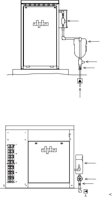
2.0Site Preparation, continued
2.4Natural Gas Meter Configurations
The gas utility company should have the meter installed prior to generator arrival. Meter configurations must comply with local codes. The illustrations provided are for illustrative purposes only.
Gas Utility Box |
Natural Gas Meter |
Street Regulator |
Manual Shutoff |
 Excess Flow Valve
(optional)
Street Pressure
Fig. 2-5, Collocated Natural Gas Meter Setup for CE-3x2 Generator
Natural Gas Meter |
Street Regulator |
Manual Shutoff |
|
|
|
|
|
|
|
|
|
|
|
|
|
|
|
|
|
|
|
|
|
|
|
|
|
|
|
|
|
|
|
|
|
Excess Flow Valve |
|
|
|
|
Street Pressure |
|||||
|
|
|
|
|
|
|
|
|||
(optional) |
|
|
|
|
|
|
|
|
||
|
|
|
|
|
|
|
|
|||
Fig. 2-6, Collocated Natural Gas Meter Setup for PN-6x-T 7.5kW System
042-288-B0-001, Rev. A |
25 |

2.0Site Preparation, continued
2.4Natural Gas Meter Configurations, continued
The gas utility company should have the meter installed prior to generator arrival. Meter configurations must comply with local codes. Examplesz provided are for illustrative purposes only.
Street Regulator
Manual Shutoff
 Gas Utility Box
Natural Gas Meter
Excess Flow Valve
(optional)
Street Pressure
Fig. 2-7, Collocated CE-3x2 5K-T Generator with Remote Natural Gas Meter
Street Regulator
Manual Shutoff
Natural Gas Meter
Manual
shutoff required if meter cannot be seen
Excess Flow Valve
(optional)
Street Pressure
Fig. 2-8, Remote Natural Gas Meter Setup for PN-6x-T 7.5kW Generator
26 |
042-288-B0-001, Rev. A |
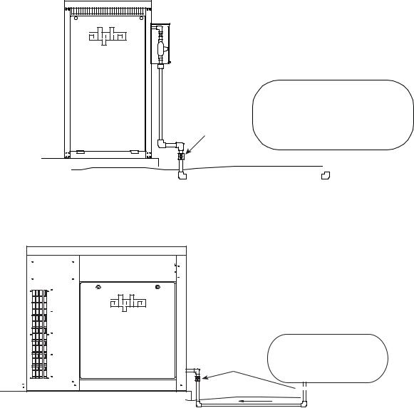
2.0Site Preparation, continued
2.5Liquid Propane Systems
For systems using liquid propane, the end user must provide a suitable LP tank. For collocated propane enclosures, see the CE-G Series Enclosure Installation Manual, Alpha P/N 031-093-C0-001, located at www.alpha.com.
|
Manual |
User-provided LP Tank |
|||
|
Shutoff |
|
|
|
|
|
|
|
|
|
|
|
|
|
|
|
|
|
|
|
|
|
|
Fig. 2-9, Liquid Propane Setup, CE-3x2 5K-T
Manual
Shutoff User-provided LP Tank
Location

 (Most Common)
Fig. 2-10, Liquid Propane Setup, PN-6x-T 7.5kW
042-288-B0-001, Rev. A |
27 |
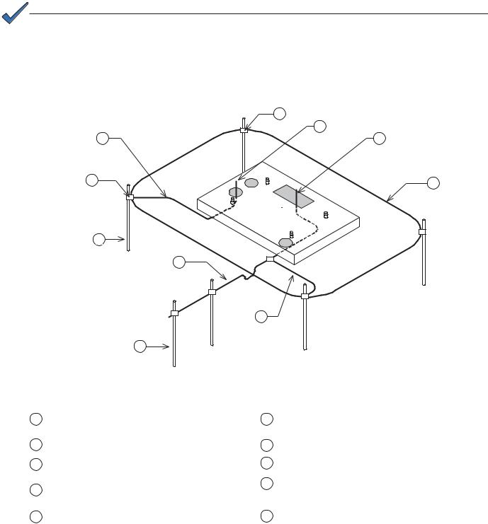
2.0Site Preparation, continued
2.6Grounding Requirements, CE-3x2 5K-T
The ground rod system is typically used in remote applications where the generator is located away from the power supply enclosure and exposed to lightning strikes, or coincidental surges. The wiring interface between the DC Genset and system carries a system ground to ensure common ground between both cabinets and communication devices. The remote APU cabinet ground rod serves only as an alternate discharge path.
NOTE:
Alpha Technologies recommends using the grounding method illustrated below. The grounding method for a particular site will be dependant upon soil type, available space, local codes, NEC (National Electric Code), and other sitespecific characteristics.
Alpha Technologies recommends 5 ohms minimum ground resistance between enclosure and ground rods, in accordance with IEEE 1100-1999 Powering and Grounding Electronic Equipment. NEC minimum grounding standard is 25 ohms.
Alpha Technologies assumes no responsibility or liability for failure of the installer to comply with the requirements of all applicable local and national codes. Where allowed, exothermic welding may be used as an alternative to Burndy clamps and connectors.
|
6 |
5 |
7 |
8 |
|
4 |
9 |
3
1
10
2
1
2
3
4
5
Fig. 2-11, Enclosure Grounding, CE-3x2 5K-T
(for reference only)
Service grounding (required). #6AWG Copper wire from |
6 |
Burndy YGHP58C2W-3 or equivalent compression ground |
|
service entrance ground bar. |
|
tap connector |
|
Two ground rods, 6' apart |
7 |
Terminate at ground bar |
|
Lightning protection (optional). 1/2" x 8' Copper ground |
8 |
Terminate at ground bar |
|
rods, 4 places. |
|
#6 bare copper loop terminated at each ground rod, 30” below |
|
|
9 |
||
Burndy YGHP58C2W-3 or equivalent compression ground |
grade (min). Corrosion-proof (25 yr. life-span) connections |
||
|
|||
tap connector |
|
suitable for direct burial MUST be used |
|
#6 bare copper wire from loop to enclosure ground bar |
10 |
#2 AWG wire |
28 |
042-288-B0-001, Rev. A |

2.0Site Preparation, continued
2.7Grounding Requirements, PN-6xT 7.5kW
The ground rod system is typically used in remote applications where the generator is located away from the power supply enclosure and exposed to lightning strikes, or coincidental surges. The wiring interface between the DC Genset and system carries a system ground to ensure common ground between both cabinets and communication devices. The remote APU cabinet ground rod serves only as an alternate discharge path.
A |
B |
Conduit |
AC In |
DC Out |
Ground |
Front of Enclosure
A
• 8 feet long, 1/2 inch diameter copper electrode.
• To aid in serviceability, place the ground electrode outside the concrete pad’s perimeter. Consult local utility codes for additional cabinet grounding and utility requirements.
B• #6AWG bare copper wire exposed 5 feet above grade (min.) for output ground bus bar.
• Clamp #6AWG bare copper wire exposed 5 feet above grade (min.) for output ground bus bar.
Fig. 2-12, Enclosure Grounding, PN-6x-T 7.5kW
042-288-B0-001, Rev. A |
29 |
 Loading...