


Alpha FXM350/ Micro350 UPS
Installation and Operation Manual
Part # 017-241-B0
Effective 11/11
member of The  Group™
Your Power Solutions Partner

Alpha FXM350 and Micro350 UPS
Installation and Operation Manual
NOTE:
Photographs contained in this manual are for illustrative purposes only. These photographs may not match your installation.
NOTE:
Operator is cautioned to review the drawings and illustrations contained in this manual before proceeding. If there are questions regarding the safe operation of this powering system, contact Alpha Technologies or your nearest Alpha representative.
NOTE:
Alpha shall not be held liable for any damage or injury involving its enclosures, power supplies, generators, batteries, or other hardware if used or operated in any manner or subject to any condition inconsistent with its intended purpose, or if installed or operated in an unapproved manner, or improperly maintained.
For technical support, contact Alpha Technologies:
Canada and USA: 1-888-462-7487 International: +1-604-436-5547
Email: support@alpha.ca
Copyright
Copyright © 2011 Alpha Technologies Ltd. All rights reserved. Alpha is a registered trademark of Alpha Technologies.
No part of this documentation shall be reproduced, stored in a retrieval system, translated, transcribed, or transmitted in any form or by any means manual, electric, electronic, electromechanical, chemical, optical, or otherwise without prior explicit written permission from Alpha Technologies.
This document, the software it describes, and the information and know-how they contain constitute the proprietary, confidential and valuable trade secret information of Alpha Technologies, and may not be used for any unauthorized purpose, or disclosed to others without the prior written permission of Alpha Technologies.
The material contained in this document is for information only and is subject to change without notice. While reasonable efforts have been made in the preparation of this document to assure its accuracy, Alpha Technologies assumes no liability resulting from errors or omissions in this document, or from the use of the information contained herein. Alpha Technologies reserves the right to make changes in the product design without reservation and without notification to its users.
Table of Contents
1. Safety 7
1.1 Safety Symbols 7 1.2 General Warnings 8 1.3 Battery Safety 8 1.4 Work Environment Safety 9 1.5 Certifications and Compliances 10
2. General Description 11
2.1 Alpha FXM350 11 2.2 Micro350/ Alpha FXM350 11 2.3 FXM350 Front Panel 13 2.4 Micro350 Top Panel 16
3. Site Planning 17
3.1 Safety Precautions 17 3.2 Electromagnetic Compatibility (EMC) Requirements 18 3.3 Mounting Options for the Micro350 (XL and XL3) 18 3.4 Options for Communicating with the FXM 22
4. Unpacking the Equipment 23
4.1 Alpha FXM350/Micro350 Configuration 23
4.2 Unpacking 23
4.3 Optional Items 23
5. Installation 24
5.1 Installation of the Micro350 24 5.2 Mounting and Wiring the FXM350 as a standalone device 31 5.3 Wiring the External Batteries and Optional Battery Heater Mats 33 5.4 Start-Up 35
6. Theory of Operation 36
6.1 Block Diagram 36
6.2 Modes of Operation 36
2 |
017-241-B0 Rev B |
7. Operating the FXM350 40
7.1 Switching the Alpha FXM On and Off 40 7.2 Operating from the Control Panel Interface 42 7.3 Operating via the FXM Communication Module (Intranet or Internet) 49 7.4 The Alpha UPS Monitor Interface 73 7.5 HyperTerminal Interface 76
8. Maintenance 89
8.1 Updating the Software 89 8.2 Testing and Replacing the Batteries 92 8.3 Preventive Maintenance 95
9. Troubleshooting 96
9.1 Procedure 96
10. Specifications 98
11. Warranty 101
12. Emergency Shutdown Procedure 102
List of Figures
Figure 1 — Micro350 cabinets 11 Figure 2 — FXM350 mounted in a standard Micro350 cabinet 12 Figure 3 — FXM 350 front panel description 13 Figure 4 — User input layout 14 Figure 5 — Contact Layout (Standard for C1 and C2) 15 Figure 6 — Micro350 Top Panel 16 Figure 7 — Mounting the Micro350 18 Figure 8 — Mounting on optional pedestal 19 Figure 9 — FXM350 Mounting Dimensions 20 Figure 10 — Rack-mount options 20 Figure 11 — FXM350 with ears for rack mounting 21 Figure 12 — Alpha FXM Communication Options 22 Figure 13 — Mounting to a wooden pole 25 Figure 14 — Securing the enclosure to the mounting bracket 25
017-241-B0 Rev B |
3 |
Figure 15 — Attaching the mounting bracket to the wall studs 27 Figure 16 — AC Power distribution terminal blocks 28 Figure 18 — Terminal block wiring 29 Figure 17 — Wiring the Micro350 29 Figure 19 — Ferrite ring installed on RJ45 network cable 30
Figure 20 — FXM350 with rack-mount ears and signal assembly option (wiring box not shown)
31 Figure 21 — FXM350 Electrical Connections 32 Figure 22 — External Battery Wiring (for 48 VDC string (top) and 24 VDC string) 33 Figure 23 — Securing the batteries with the optional restraining bar 34 Figure 24 — FXM 350 block diagram 36 Figure 25 — Battery charging in line mode 38 Figure 26 — Back up power from batteries 38 Figure 27 — LCD Control Panel Logo Screen 42 Figure 28 — LCD Menu Tree 44 Figure 29 — Web GUI (UPS Specification Screen shown) 49 Figure 30 — Alpha UPS Monitor: UPS Communications screen 50 Figure 31 — Web GUI: UPS Specification screen 51 Figure 32 — Web GUI: Input & Output screen 52 Figure 33 — Web GUI: Battery & Inverter screen 52 Figure 35 — Web GUI: User Input Status screen 53 Figure 34 — Web GUI: Relay & Load Shed screen 53 Figure 36 — UPS Maintenance: Unit Configuration screen 54 Figure 37 — Restore all default commands 54 Figure 38 — UPS Maintenance: Battery screen 56 Figure 39 — UPS Maintenance: Inverter screen 57 Figure 40 — UPS Maintenance: Relay & Load Shed screen 58 Figure 41 — Programmable Timer Operation 59 Figure 42 — Time Of Day Action Operation 59 Figure 43 — Time Of Day Configuration 60 Figure 44 — Time Of Day Action Status 60 Figure 45 — Assigning the Temperature trigger function to a dry contact – Alpha UPS Monitor
4 |
017-241-B0 Rev B |
|
61 |
Figure 46 — Setting the Temperature trigger value |
61 |
Figure 47 — UPS Maintenance: Time & Date screen |
62 |
Figure 48 — UPS Maintenance: Password screen |
62 |
Figure 49 — User Input Configuration: Setting the Trigger Type |
63 |
Figure 50 — User Input Configuration: Setting the Logic Level |
63 |
Figure 51 — User Input Configuration: Setting an Action |
64 |
Figure 52 — User Input Current Status |
64 |
Figure 53 — User Input Current Status |
64 |
Figure 54 — Alarms & Faults screen |
65 |
Figure 55 — Event History screen |
65 |
Figure 56 — Event Log Monitor screen |
66 |
Figure 57 — Event Log Monitor, Open Event File window |
67 |
Figure 58 — Alpha UPS Monitor: Upgrade Firmware |
67 |
Figure 59 — Upgrade Communication Module |
68 |
Figure 60 — Alpha UPS Monitor: Configure Site Information |
68 |
Figure 61 — Configure SNMP screen |
69 |
Figure 62 — Email Notification screen |
69 |
Figure 63 — Test email feature |
70 |
Figure 64 — Alpha UPS Monitor (UPS Specification Screen shown) |
73 |
Figure 65 — Add or Remove Programs Window |
74 |
Figure 66 — HyperTerminal communication parameters |
76 |
Figure 67 — Main Menu Screen |
77 |
Figure 68 — Menu Tree |
78 |
Figure 69 — Temperature trigger function via HyperTerminal |
84 |
Figure 70 — Typical Discharge Characteristics for Lead Acid Batteries |
92 |
Figure 71 — Battery string example |
104 |
Figure 72 — Edge Trigger |
106 |
Figure 73 — Level Trigger |
106 |
Figure 74 — Level Alternative |
107 |
017-241-B0 Rev B |
5 |
List of Tables
Table A — UPS Operating Modes 43 Table B — Control Menu 45 Table C — System Status Menu 47 Table D — List of Parameters 55 Table E — Line Status (see Figure 67) 79 Table F — Output Status (see Figure 67) 79 Table G — Faults (see Figure 67) 80 Table H — Alarms (see Figure 67) 80 Table I — Maintenance Submenu 81 Table J — Dry Contact Configuration Settings 82 Table K — Setting the Timer Contact 83 Table L — Setting the Date and Time 85 Table M — Event Codes 87 Table N — Battery Temperature Compensation Values 93 Table O — Alarm Submenu 96 Table P — Fault Submenu 97 Table Q — Problems Not Reported by System 97 Table R — Mechanical Specifications 98 Table S — Electrical Specifications 99 Table T — Boost/Buck/Line Transfer Thresholds 100 Table U — Regulatory 100
6 |
017-241-B0 Rev B |

1. Safety
SAVE THESE INSTRUCTIONS: This manual contains important safety instructions that must be followed during the installation, servicing, and maintenance of the product. Keep it in a safe place. Review the drawings and illustrations contained in this manual before proceeding. If there are any questions regarding the safe installation or operation of this product, contact Alpha Technologies or the nearest Alpha representative. Save this document for future reference.
1.1 Safety Symbols
To reduce the risk of injury or death, and to ensure the continued safe operation of this product, the following symbols have been placed throughout this manual. Where these symbols appear, use extra care and attention.
The use of ATTENTION indicates specific regulatory/code requirements that may affect the placement of equipment and /or installation procedures.
NOTE:
A NOTE provides additional information to help complete a specific task or procedure. Notes are designated with a checkmark, the word NOTE, and a rule beneath which the information appears.
 CAUTION!
CAUTION indicates safety information intended to PREVENT DAMAGE to material or equipment. Cautions are designated with a yellow warning triangle, the word CAUTION, and a rule beneath which the information appears.
WARNING!
WARNING presents safety information to PREVENT INJURY OR DEATH to personnel. Warnings are indicated by a shock hazard icon, the word WARNING, and a rule beneath which the information appears.
HOT!
The use of HOT presents safety information to PREVENT BURNS to the technician or user.
017-241-B0 Rev B |
7 |

1.2 General Warnings
You must read and understand the following warnings before installing the product. Failure to do so could result in personal injury or death.
•Read and follow all instructions included in this manual.
•Only qualified personnel are allowed to install, operate and service this system and its components.
 CAUTION!
Risk of Electric Shock. See Installation Instruction before connecting to the supply.
•The FXM350/ Micro350 is only intended for restricted access locations
•The UPS shall be connected only to a dedicated branch circuit.
 CAUTION!
To reduce the risk of fire, connect only to a maximum branch circuit overcurrent protection in accordance with the National Electrical Code, ANSI/NFPA 70.
•Always assume electrical connections or conductors are live. Switch all circuit breakers and double check connections with a voltmeter before performing installation or maintenance.
•A disconnect switch shall be provided by others for the AC input and AC output circuits.
•The branch circuit overcurrent protection for the AC input and AC output circuit shall be provided in the end installation.
•Place warning label(s) on the utility panel to tell emergency personnel that a UPS is installed.
•Use only proper lifting techniques whenever handling equipment, parts, or batteries.
•Ferules or the equivalent must be used when stranded wire is used on the AC input and output terminal blocks.
WARNING!
The Alpha FXM350/ Micro350 have more than one live input circuit. AC power may be present at the outputs even if the system is disconnected from line or battery power.
 CAUTION!
The Alpha FXM350/ Micro350 metal surfaces can be very hot to the touch.
1.3 Battery Safety
•Battery Installation and servicing should be performed or supervised by personnel knowledgeable about batteries and the required precautions performed.
•Be extra cautious when connecting or adjusting battery cabling. An improperly connected battery cable or an unconnected battery cable can result in arching, fire or explosion.
•Before attaching the batteries to the Alpha FXM350/ Micro350, make sure that the polarity is correct.
•Use new batteries when installing a new unit. Verify that all batteries are the same type with identical date codes.
•When replacing batteries, use sealed lead acid batteries, rated 12 V. Never install old or untested batteries.
•Batteries that show signs of cracking, leaking or swelling must be replaced immediately by authorized personnel using a battery of identical type and rating.
8 |
017-241-B0 Rev B |
 CAUTION!
Never open, damage or mutilate batteries. Released Electrolyte is harmful to the skin and eyes. It may be toxic and hazardous to the environment.
•Never dispose of batteries in a fire. The batteries may explode. Follow the manufacturer’s directions and check with your local jurisdictions for safe battery disposal.
•If electrolyte splashes on your skin, immediately wash the affected area with water. If electrolyte gets into your eyes, wash them for at least 10 minutes with clean running water or special neutralizing eye wash solution. Seek medical attention at once.
•Neutralize spilled electrolyte with special neutralizing solution and a “spill kit” or solution of 1 lbs (0.45KG) of baking soda (bicarbonate of soda) in 1 gallon (3.8 L) of water.
 CAUTION!
A battery can present a risk of electrical shock and high short-circuit current. The following precautions should be observed when working on batteries:
a.Remove watches, rings, or other metal objects.
b.Use tools with insulated handles.
c.Wear rubber gloves and boots.
d.Do not lay tools or metal parts on top of batteries.
e.Disconnect the charging source before connecting or disconnecting battery terminals.
f.Determine if the battery is inadvertently grounded. If inadvertently grounded, remove the source from the ground. Contact with any part of a grounded battery can result in electrical shock. The likelihood of such shock can be reduced if the grounds are removed during installation and maintenance (applicable to equipment and remote battery supplies not having a grounded supply circuit).Never let live battery wires touch the Alpha FXM350/ Micro350, the enclosure or any other metal objects. This can cause a fire or explosion.
•Do not smoke or introduce sparks in the vicinity of a battery.
•If the batteries have been in storage for more than 3 months, recharge them for at least 24 hours and then test them with a load before installation.
•Each AlphaCellTM battery has a date code found on the warning label which must be recorded in the maintenance log. If non-Alpha batteries are used, see the manufacturer’s documentation for date code type and placement.
1.4 Work Environment Safety
•Do not work alone under hazardous conditions.
•Keep the chassis area clear and dust-free during and after the installation.
•Keep tools away from walk areas where you or others could fall over them.
•Wear safety glasses when working under any conditions that might be hazardous to your eyes.
•Do not work on the unit or connect or disconnect cables during periods of lightning activity.
017-241-B0 Rev B |
9 |
1.5 Certifications and Compliances
The Alpha FXM350 and Micro350, has been designed, manufactured, and tested to the requirements of the following national and international safety standards:
•CAN/CSA-C22.2 No. 107.3-05 – Uninterruptible Power Systems; additional requirements (RD): CAN/ CSA-C22.2 No. 60950-1-03 - Information Technology Equipment - Safety.
•UL 1778 (Edition 4) – Uninterruptible Power Systems; additional requirements (RD): UL 60950-1 (Edition
1)- Information Technology Equipment - Safety.
•FCC CFR47 Part 15 Class A – This equipment has been tested and found to comply with the limits for a Class A digital device pursuant to part 15 of the FCC Rules. These limits are designed to provide reasonable protection against harmful interference when the equipment is operated in a commercial environment. This equipment generates, uses, and can radiate radio frequency energy and, if not installed and used in accordance with the instruction manual, may cause harmful interference to radio communications. Operation of this equipment in a residential area is likely to cause harmful interference in which case the user will be required to correct the interference at his own expense.
•Industry Canada - This Class A digital device apparatus complies with Canadian ICES-003.
•Industry Canada - Cet appareil numrique de la Classe A est conformé la norme NMB-003 du Canada.
10 |
017-241-B0 Rev B |

2. General Description
2.1 Alpha FXM350
The Alpha FXM350 is available in 24Vdc and 48Vdc models. It provides up to 350W of regulated AC Power to the load, when utility power is available, and provides back up power from the batteries in case of a utility power failure. Noteworthy features include:
•Local or remote monitoring and control via USB and SNMP communication
•Small footprint for wall, rack or enclosure mounting
•Dependable operation in extreme operating environments (-40 to 74°C or -40 to 165°F)
•Powerful firmware with enhanced features such as battery run-time information
2.2 Micro350/ Alpha FXM350
The Micro350 contains a standard FXM350 along with batteries—Figure 1 shows three options for the enclosure. These enclosures are designed with a NEMA 3R rating for outdoor applications.
Figure 2 shows the FXM350 installed in a standard-sized Micro350 cabinet. Power is distributed through terminal blocks mounted on a DIN rail.
(a)Standard Micro350 |
(b) Micro350 XL |
(c) Micro350 XL3 |
(1 battery tray) |
(2 battery trays) |
(4 battery trays) |
|
Figure 1 — Micro350 cabinets |
|
017-241-B0 Rev B |
11 |

In addition to the FXM350 standard features, the unit also includes the following:
•Three additional user-configurable dry contacts and two additional user inputs (top panel in Figure 2)
•Door sensor switch for increased security
•AC Input and outputs on an easy to install terminal block
•Flexible dual AC and DC output for multiple loads up to 350W with distribution
AC input |
Battery bus voltage |
AC output (dual) |
120Vac |
48V or 24V |
120/24Vac |
230Vac |
24V |
230/24Vac |
Micro350 top panel
FXM350 front panel
AC power distribution terminal blocks
Wire management panel
Attachment holes for

 mounting bracket
Ground stud
Knockouts for wiring
Figure 2 — FXM350 mounted in a standard Micro350 cabinet
12 |
017-241-B0 Rev B |

2.3 FXM350 Front Panel
The following table and Figure 3 identify the main features of the FXM350 which are described in detail in the following pages.
Item |
Description |
Item |
|
Description |
|
|
|
|
|
|
|
1 |
Battery breaker |
8 |
Optically isolated user inputs |
|
|
|
|
|
|
||
2 |
Battery connector |
9 |
Additional user inputs and dry contacts connector |
||
|
|
|
|
|
|
3 |
RJ45 communication module connector |
10 |
Status and alarm LEDs |
|
|
4 |
LCD control panel and menu navigation buttons |
11 |
Configurable dry contacts, C1 and C2 |
||
|
|
|
|
|
|
5 |
USB communication connector |
12 |
Replaceable fan assembly |
|
|
|
|
|
|
|
|
6 |
Battery temperature sensor connector |
13 |
AC input circuit breaker |
|
|
|
|
|
|
|
|
7 |
Battery voltage test points |
14 |
Battery heater mat connector |
|
|
|
|
|
|
|
|
|
|
15 |
AC input/output connections |
|
|
|
|
|
|
|
|
|
1 |
|
|
|
|
|
4 |
|
10 |
12 |
13 |
|
|
|
|||
|
2 |
|
|
|
|
3
7
5
6 |
8 |
9 |
11 |
14 |
15 |
|
|
Figure 3 — FXM 350 front panel description |
|
|
|
1Battery breaker
This circuit breaker provides over-current protection and is used as an on/off switch for the battery power. It must be switched on for proper Alpha FXM operation.
2Battery connector
The battery connector connects the external batteries to the Alpha FXM.
3RJ45 communication module connector
This RJ-45 connector is the Alpha FXM Ethernet connector.
4LCD control panel and menu navigation buttons
The LCD control panel together with the cancel, scroll and select buttons are used to monitor and control the Alpha FXM350.
5USB communication connector
This USB communication connector provides a direct connection to the USB port of a standard computer USB port (USB 2) for remote monitoring.
017-241-B0 Rev B |
13 |

6Battery temperature sensor connector
The battery charging voltage is temperature dependant. A battery temperature sensor connects to the Alpha FXM so that the Alpha FXM microprocessor can adjust the charging voltage for optimum charging.
The sensor MUST be attached to the Alpha FXM for normal operation. If the sensor is not attached, a “Temperature Probe Unplugged” alarm appears on the LCD.
7Battery voltage test points
These test points let you measure the battery voltage. They accept 2 mm diameter test probe tips. The battery circuit breaker must be on to measure the voltage.
The battery voltage test points are not to be used as a power outlet.
8 Optically isolated user inputs
These optically isolated inputs are used to attach an external switch panel for remote control of the Alpha FXM.
The User Input connector has three contacts (Figure 4) that are used to control the Alpha FXM. The default settings for the user inputs are as follows:
1 (S1): Shorting this contact to Common starts the Alpha FXM battery test. See "Battery Test" on page 95.
2 (S2): Shorting this contact to Common activates an alarm. See "7.3.4.9 Maintenance > User Input" on page 63.
3 (SC): Isolated return for contacts S1, and S2.
|
|
|
|
|
|
|
|
|
|
|
|
|
|
|
|
|
|
|
|
|
|
|
|
|
|
|
|
|
|
|
|
|
1 |
|
2 |
|
3 |
|
|||||
S1:Self Test |
S2:Alarm |
SC:Common |
||||||||
Figure 4 — User input layout
9 Additional user inputs and dry contacts connector
Enables connection to 3 dry contacts and 2 user inputs on the Micro350 top panel or to optional rack mounting ears (see Figure 20).
10 Status and Alarm LEDs Status:
Green LED solidly illuminated: the Alpha FXM is in Line mode and line power is provided to the load. Green LED flashing: the unit is in Inverter mode and backup battery power is provided to the load.
Alarm:
Red LED solidly illuminated: fault in the Alpha FXM. (See "Table P — Fault Submenu" on page 97.) Red LED flashing indicates an alarm. ( See "Table O — Alarm Submenu" on page 96.)
14 |
017-241-B0 Rev B |

11 Configurable dry contacts, C1 and C2
Contacts C1 and C2 allow the Alpha FXM to be connected to an external monitoring panel or to traffic control equipment.
The factory default settings can be reprogrammed to meet your requirements. See "7.3.3.3 Monitoring > Relay & Load Shed" on page 53 for web and Alpha UPS Monitor, and "7.5.4 Programming the Dry Contacts" on page 82 for HyperTerminal.
C1: The C1 contact is energized when line power is unqualified and the Alpha FXM provides backup battery power to the load(s). Can be used to generate an “On Battery” alarm.
C2: This contact is energized when the battery drops below a pre-set voltage level. Can be used to generate a “Low Battery” alarm. You can change the pre-programmed level to match the batteries used and the actual operating conditions. See "Adjusting and Controlling the Alpha FXM" on page 81: #35 Low Battery Warning Voltage.
The contacts have a maximum rating of 1A at 250V.
Normally
Open (NO)
Microprocessor
UPS
Interior
Normally
Closed (NC)
Common (C)
Figure 5 — Contact Layout (Standard for C1 and C2)
12 Replaceable fan assembly
This microprocessor-controlled fan regulates the Alpha FXM internal temperature for optimum performance. Microprocessor-control of the fan speed increases the life of the internal electronics and the fan.
Take care that the fan is not blocked. Failure of the fan generates an alarm; the internal fan assembly is designed so it can be replaced if it fails.
13 AC input circuit breaker
This circuit breaker is an on/off switch for the line power into the Alpha FXM ,which also provides input protection. It must be switched on for proper Alpha FXM operation.
14 Battery heater mat connector
This connector plugs into a 55W heater mat (optional). The Alpha FXM senses the battery temperature through the battery temperature sensor (explained in 6 above) and controls the battery heater mat. The heater mat is set to turn on at 5°C or less and turns off at 15°C.
15 AC input/output connections
The terminal blocks provide connections to the AC input and loads for dual outputs.
017-241-B0 Rev B |
15 |
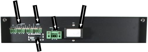
2.4 Micro350 Top Panel
The Micro350 top panel has three additional dry contacts and two user inputs.
The panel also has a door interlock and auxiliary contacts, which can be wired to a user input to generate an alarm when the door is open.
Dry contacts |
User inputs |
|
C3, C4, and C5 |
|
|
|
S3 and S4 |
Door interlock |
|
|
Open door |
|
|
switch signal |
Additional signals connector.
Connects to #9 of figure 3
Figure 6 — Micro350 Top Panel
16 |
017-241-B0 Rev B |

3. Site Planning
 WARNING!
Restricted Access: The Alpha FXM350 and Micro350 must be installed in a restricted area accessible only by qualified service personnel.
The Alpha FXM350 and Micro350 are intended for permanent AC connection only.
The Alpha FXM350 and Micro350 must be correctly grounded for proper operation. Older facilities may have inadequate electrical grounding. Inspection must be performed by a qualified electrician before installation to ensure that grounding meets the local electrical code.
The utility line attached to the Alpha FXM input MUST be protected by a circuit breaker certified for this use in accordance with the local electrical code. The UPS must be connected only to a dedicated branch circuit.
The UPS equipment that is powered by this service panel requires the neutral to be permanently bonded to the ground. Always disconnect the batteries before servicing the circuit breaker panel.
The input and output lines to and from the Alpha FXM MUST have disconnect devices attached.
The Alpha FXM is suitable for installations in network telecommunication facilities and locations where the National Electrical Code applies.
Grounding: The Alpha FXM is suitable both for installation as part of a common bonding network (CBN) and an isolated bonding network.
For installations above 1400 m (4500 ft) elevation, additional cooling may be needed to reduce the operating temperature of the Alpha FXM. The maximum allowable operating temperature must be reduced by 2°C (3.5 °F) for every 300 m (1000 ft) above 1400 m (4500 ft).
3.1 Safety Precautions
•Install the Alpha FXM350 and Micro350 and batteries on a surface that can support the total weight. See Chapter "10. Specifications" on page 98.
•The input wiring must reach a suitably grounded power outlet and the load wiring must reach the Alpha FXM350 and Micro350 output terminal blocks.
•Place the Alpha FXM350 in a properly sheltered location or inside a weather-proof enclosure to protect the electronics from water, dust and other possible contamination.
•Backup Generator (If used)
In Generator mode, the Alpha FXM range of acceptable input frequency and voltage is expanded to accept the fluctuations created by a generator. See "7.2.2 The LCD Control Menu" on page 45, Table B,
Sense Type.
Use a generator with electronic speed and voltage controls which produces less than 10% voltage total harmonic distortion (THD). Mechanical governors can force the Alpha FXM to run continuously in Battery mode. Before installation, make sure the generator’s output voltage is compatible with the Alpha FXM input voltage requirements. To make sure the system runs smoothly, use a generator that supplies twice as much power as drawn by the total load.
017-241-B0 Rev B |
17 |
3.2 Electromagnetic Compatibility (EMC) Requirements
Observe the following EMC requirements when setting up the Alpha FXM and its internal equipment:
•All AC mains and external supply conductors must be enclosed in a metal conduit or raceway when specified by local, national, and/or other applicable government codes and regulations.
•The customer facilities must provide suitable surge protection.
•To meet FCC Class B requirements, follow the instructions in section 5.1.4 to attach a ferrite ring to the connector end of your RJ45 network cable.
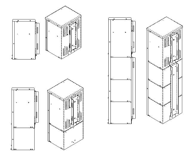
3.3 Mounting Options for the Micro350 (XL and XL3)
Figure 7 shows the mounting hardware for the various configurations of the Micro350. Choose from the following options for mounting the Micro350:
•Mounting to a wooden pole, 5.1.1.1 on page 24.
•Mounting to a steel or concrete pole, 5.1.1.3 on page 26.
•Mounting to a wall, 5.1.1.4 on page 27.
Optional pedestal mounting is shown in Figure 8.
Micro Standard
Micro XL3
NOTE: To install a Micro XL3 enclosure, first attach the XL to an XL3 kit.
Micro XL
Figure 7 — Mounting the Micro350
18 |
017-241-B0 Rev B |
Figure 8 — Mounting on optional pedestal
3.3.1 Battery Heater Mats
The FXM350 and Micro350 allow connection, on its front panel, of a battery heater mat without a thermostat (#14 in Figure 3). Maximum power of the battery heater mat for use with the FXM350 connector is 55W. The FXM turns the heater mat on when the temperature measured by the battery temperature sensor senses a temperature < 5°C. It turns the heater mat off when the temperature raises to >15°C. For the Micro350XL or bigger systems needing more than one heater mat, it is recommended to use the heater mats with built in thermostat and daughter heater mats that can be daisy chained. These heater mats may be wired to the AC in the terminal block on the distribution panel. Ensure that the input breaker is appropriately rated.
017-241-B0 Rev B |
19 |

3.3.2 Mounting options for the FXM350
Figure 9 and Figure 11 provide dimensions for mounting the FXM350 UPS as a standalone device.
198 |
[7.8] |
|
13.7 [0.5] |
88 [3.5]
342 [13.5]
Figure 9 — FXM350 Mounting Dimensions
3.3.2.1 Standalone Configurations:
•Wall mounted, with front access, onto a 19" mounting tray that includes a battery cabinet
•Rack mounted in a 19" or 23" rack with add-on ears and a wiring box (Figure 10). An optional signals assembly can be ordered, which pro-
vides two user inputs and three dry contacts.
Optional signals assembly
Standard ears and wiring box
Figure 10 — Rack-mount options
20 |
017-241-B0 Rev B |

B Rev B0-241-017
TYP. 6.35[0.250] X 9.53[0.375]
OBROUND THRU
566.7 |
22.31 |
584.1 |
23.00 |
43.7 1.72
46.0 1.81
FXM 350 w/RACK MOUNT KIT CONFIGURED FOR A 23" RACK |
FXM 350 w/RACK MOUNT KIT CONFIGURED FOR A 19" RACK |
& OPTIONAL EXTERNAL DRY CONTACTS MODULE |
& OPTIONAL EXTERNAL DRY CONTACTS MODULE |
88.1 |
3.47 |
76.2 |
3.00 |
|
|
|
|
465.1 |
18.31 |
|
|
|
482.5 |
19.00 |
Figure 11 — FXM350 with ears for rack mounting
21
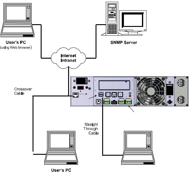
3.4 Options for Communicating with the FXM
There are several ways to communicate with the Alpha FXM UPS:
1.The control panel page 42).
2.Window®’s HyperTerminal or other terminal emulation program to access the UPS command line system over the USB interface (page 76).
3.Alpha UPS Monitor installed on your computer and connected to the FXM over the USB interface . The Alpha UPS Monitor software can be downloaded from www.alpha.ca./downloads/.
4.Factory-installed FXM communication module to communicate with the Alpha FXM using any of the following:
•On site PC
•Company intranet or the internet using a web browser (page 49).
•SNMP communications
Option 4
Option 5
On-Site
Ethernet Connection
FXM350 UPS
Ethernet |
USB Port |
Port |
|
Option 4 |
Option 1:
Control Panel
Options |
2 and 3 |
|
User’s PC |
(Use a Web browser for |
(Use Alpha UPS Monitor |
Ethernet connection |
or HyperTerminal) |
to on-site computer) |
|
Figure 12 — Alpha FXM Communication Options
22 |
017-241-B0 Rev B |

4. Unpacking the Equipment
4.1 Alpha FXM350/Micro350 Configuration
The Alpha FXM is factory installed inside the Micro350 prior to shipping.
 WARNING!
The Alpha FXM350/Micro350 combination is heavy, up to 12 kg (26 lb). Use proper lifting techniques.
4.2 Unpacking
1.Select a suitable area for unpacking.
2.Store all the packing material and boxes for possible equipment returns.
4.2.1 FXM350 Standalone or Micro350 (XL)
1.Check the contents in your product package. The following standard items are shipped together in a plastic bag:
•Terminal blocks and labels for the dry contacts
•Temperature sensor cable
•Battery clip with screws
•AC plate with screws and bushing
•Ferrite ring
•Cable tie
•Operator’s manual
•USB cable
2.Compare the packing slip and the list of parts with the items you received. If the list of parts on your packing slip does not match the items you received, or any items appear damaged, immediately notify your carrier agent and the supplier who prepared your shipment.
4.3 Optional Items
Optional items may include:
•Battery heating mats
•Battery cable kit
•Rack mount ears and wiring box kit for mounting in a 19" or 23" rack (Figure 10)
•Optional signals assembly for FXM350 (Figure 20)
•Distribution panel
Batteries, if ordered from Alpha, will ship separately.
017-241-B0 Rev B |
23 |

5. Installation
 WARNING!
To avoid personal injury or damage to the equipment, always use at least two installation personnel to remove the unit from its container.
.1 Installation of the Micro350
 WARNING!
Batteries or other components (with the exception of factory-installed components) must not be installed until the Micro350 cabinet has been securely set in place at its permanent location. Transporting the unit with batteries installed may cause a short circuit, fire, explosion, and/or damage to the battery pack, enclosure and installed equipment. Damage caused by improper shipping or transporting a unit with batteries installed is not covered by the warranty.
5.1.1 Mounting the Micro350 Enclosure
5.1.1.1 Mounting to a wooden pole
Have the following tools and materials on hand:
•13 mm nut driver for the bolts that attach the cabinet to the mounting bracket.
•Two 5/8 inch diameter machine bolts (UNC tread); SAE (Grade 5 or better), length to suit the pole (not provided).
•Two 5/8 inch diameter zinc-plated flat washers.
•Two 5/8 inch diameter hex nuts (UNC thread).
•Auger or drill for boring 3/4 inch diameter holes in the wood pole.
24 |
017-241-B0 Rev B |
5.1.1.2 Procedure:
1.Using the mounting bracket as a template, drill 2 holes into the pole to accept the machine bolts.
2.Secure the mounting bracket to the pole with the machine bolts as shown in Figure 13.
3.Secure the Micro350 cabinet to the mounting bracket with the supplied bolts (Figure 14).
Front |
Side |
Wood |
|
|
Pole |
|
|
|
Figure 13 — Mounting to a wooden pole
a. Hook the top of the mounting bracket under the case’s attachment fitting.
b. Secure the cabinet to the mounting bracket.
Figure 14 — Securing the enclosure to the mounting bracket
017-241-B0 Rev B |
25 |

5.1.1.3 Mounting to a Steel or Concrete Pole
Have the following tools and materials on hand:
•13 mm nut driver for the bolts that attach the cabinet to the mounting bracket.
•Two pole mount straps that fit the pole. Straps must be stainless or galvanized.
•C001 Band-It tool or equivalent.
•C206 3/4 inch stainless steel Band-It band or equivalent.
•C256 3/4 inch stainless steel Band-It buckles or equivalent.
Procedure: |
|
1. Secure the mounting bracket to the pole with |
Steel or Concrete |
the straps. |
|
|
Pole |
2. Secure the Micro350 cabinet to the mounting bracket with the supplied bolts.
a. Hook the top of the mounting bracket under the case’s attachment fitting.
b. Secure the cabinet to the mounting bracket.
26 |
017-241-B0 Rev B |

5.1.1.4 Mounting to a Wall
Have the following tools and materials on hand:
•13 mm nut driver for the bolts that attach the cabinet to the mounting bracket.
•Four 1/4" x 1-1/8" lag bolts.
•Four 1/4" diameter flat washers.
•Drill with 1/8" bit for drilling pilot holes.
•Assorted sockets and wrenches.
Procedure:
NOTE:
If the wall structure is not strong enough to support the weight of the Micro350 enclosure and batteries, use a wooden backing plate that has a minimum thickness of 1-1/4" and a maximum width of 4" that is securely mounted to a wall stud or studs.
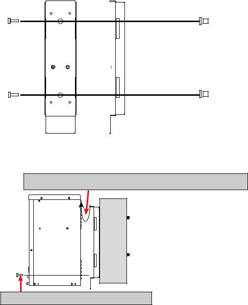
1.Using the mounting bracket as a template, drill 4 pilot holes (indicated by the arrows in the following diagram) into the wall to accept 1/4" bolts.
2.Secure the mounting bracket to the wall with the 4 bolts and washers.
3.Secure the Micro350 enclosure to the mounting bracket with the supplied bolts.
NOTE: |
|
|
|
To install a Micro XL3 enclosure, |
Front |
Side |
|
first attach the XL to an XL3 kit. |
Wall or |
||
|
|
|
|
|
|
|
studs |
Figure 15 — Attaching the mounting bracket to the wall studs
017-241-B0 Rev B |
27 |

5.1.2 Wiring the Micro350
WARNING!
Before starting, disconnect the Line power.
If stranded wires are used for connection at the input terminal block, ferrules or equivalent crimping terminals must be used.
Separate the AC input power cables from the output power cables within the Alpha FXM enclosure. Route them through separate conduit openings in the enclosure.
Separate the DC Battery cable from the AC Input and Output power cables. Route the cable through its own opening.
The AC power distribution terminal blocks in the Micro350 enclosure are located in the below the FXM350 (see Figure 16). Refer to Table S for detailed electrical specifications.
Figure 16 — AC Power distribution terminal blocks
Have the following tools and materials on hand:
•Hammer for removing the knockouts
•Slot head screwdriver, 3/16 or smaller, to attach wires to the terminal blocks for the dry contacts / user inputs on the front panel
•Slot head screwdriver, 1/4 or larger, for removing the knockouts
•DC voltmeter
•Battery terminal corrosion inhibitor such as NOCO Company’s NCP-2 or Sanchem Inc. No-Ox ID Grease “A”
•Maximum of 12 AWG wire for wiring the input and output terminal blocks
•If used, 1/2" conduit connectors to fit the knockouts (7/8" diameter) and armored conduit to fit
•Optional battery heater mats
28 |
017-241-B0 Rev B |
 Loading...