


INEX Inverter System
INEX Inverter System
User Manual
014-114-B2

Argus Technologies Ltd. Visit www.argus.ca
Burnaby, British Columbia. Telephone: 604 436 5900 Fax: 604 436 1233
Argus Technologies reserves the right to make changes to the products and information contained in this document without notice.
Copyright 2008 Argus Technologies Ltd. Argus
®
is a registered trademark of Argus Technologies Ltd. All Rights Reserved.
Printed in Canada.
This page intentionally left blank.

Argus Technologies Ltd. 014-114-B2 Rev D WC
Printed in Canada. © 2008 Argus Technologies Ltd. ARGUS and INEX are registered trademarks of Argus Technologies Ltd. All Rights Reserved.
INEX Inverter System
User Manual
014-114-B2
Applies to inverter modules 014-114-10, 014-115-10, 014-116-10, and 014-117-10.
The following documents and drawings are included in this manual to provide the necessa ry information required for
installation, operation and fault diagnosis of the unit:
• Specifications: 014-114-B1
• Installation and Operation Instructions: 014-114-C0
• Factory Service Information: 048-527-10

Specifications for INEX Inverter System
Argus Technologies Ltd. 014-114-B1 Rev D WC
Printed in Canada. © 2008 Argus Technologies Ltd. ARGUS and INEX are registered trademarks of Argus Technologies Ltd. All Rights Reserved. Page 1 of 4
Inverter Module Input
Nominal Voltage: 48Vdc
Operating Range: 40.5 to 58Vdc within rated limits
Under Voltage Warning Threshold: 45Vdc
Under Voltage Threshold: 40Vdc
Over Voltage Warning Threshold: 58Vdc
Over Voltage Threshold: 60Vdc
Isolation AC-DC: Reinforced isolation (Pri-Sec) 4242Vdc/1min
Inrush current: <2*Irated
Isolation DC-enclosure: 707Vdc (varistors and filter capacitor removed)/1min
Input Protection: Reverse polarity protection
Psophometric Noise Voltage: ≤1.0mV ITU-T O.41 (16.66 to 6000Hz)
Reflected Psophometric Noise Current: <1% according to YD/T 777-2006
Reflected Relative Band Width Current Noise: <10% (0-2MHz) according to YD/T 777-2006
Wide Band Noise: <1.0mV (psophometric, 25Hz to 5kHz)
<20mVrms (25Hz to 20kHz)
Peak to Peak Noise: <150mV up to 100MHz
Inverter Module Output
Power Capacity: 1000VA/800W,
1500VA/1200W
Waveform: Pure sine wave
Power Factor: 0.8
Nominal Output Voltage: 110/115/120Vac or 208/220/230/240Vac
Voltage Regulation: Max ±2%
Output Frequency: 50/60Hz
Frequency Variation: Max ±0.5%
Frequency Setting: Manually, field-selectable
Crest Factor: 3:1
T.H.D. (Current): <3% for linear load, <5% for non-linear load
Capacitive/Inductive Load: -0.8 to +0.8 without exceeding permissible distortion for resistive load
Efficiency: Min 88% at rated load for 48Vdc system

Specifications for INEX Inverter System Continued
Argus Technologies Ltd. 014-114-B1 Rev D WC
Printed in Canada. © 2008 Argus Technologies Ltd. ARGUS and INEX are registered trademarks of Argus Technologies Ltd. All Rights Reserved. Page 2 of 4
Current Limitation: Electronic current limitation at overloads and short circuits
Isolation AC-enclosure: Basic isolation (Pri-Gnd) 2121Vdc/1min
Surge Protection: EN61000-4-5, Telcordia GR-1089 CORE, ANSI/IEEE C62.41, STD 587-
1980
Dynamic Response: Better than ±10% according to IEC 62040-3 Class 1
Over Load Protection: 1.5*Inom >20s
1.25*Inom temperature controlled
Inom = 1000VA/output voltage
Short circuit current = 16A for INV-4810EA and 30A for INV-4810A
Load Sharing: <5%
Inverter Protection
Over Load: When load exceeds 150% of power capacity, inverter will shut down after
20 seconds, and diagnose as overload fault with red LED lit.
When load is 105~150%, inverter continuously delivers output power
with a yellow LED lit for warning.
Output Voltage Fault Detection: When the output RMS (root mean square) voltage is out of operating
voltage range, the inverter unit will diagnose as output voltage high or
low fault.
Inverter Output Short Circuit: When output RMS voltage is below 40VAC and output RMS current is
over 2A, the system will diagnose as inverter output short circuit fault
with red LED on.
Input Voltage Detection: When the DC input voltage is out of operating voltage range, the inverter
system will shut down and release visual and audio alarms.
Over Temperature: When inverte r intern al temperature rises over 100°C (212°F), the system
will diagnose as over temperature fault with red LED flicker.
Maximum Number of INEX Inverter Modules for Parallel Connection
Model With STS-050A Without STS-050A
INV-4810A (1000VA/120Vac) 6 12
INV-4810EA (1000VA/240Vac) 12 12
INV-4815A (1500VA/120Vac) 4 8
INV-4815EA (1500VA/240Vac) 8 12
Note: Static transfer switch (STS)
INEX Controller Module
DC Nominal Voltage: 48Vdc
DC Voltage Range: 30 to 70Vdc
Over Current Protection: 2A fuse
LCD Display: 3” backlit LCD screen with 4 lines by 16 characters
LED Indicators: Green/normal, yellow/warning, and red/fault

Specifications for INEX Inverter System Continued
Argus Technologies Ltd. 014-114-B1 Rev D WC
Printed in Canada. © 2008 Argus Technologies Ltd. ARGUS and INEX are registered trademarks of Argus Technologies Ltd. All Rights Reserved. Page 3 of 4
Function Keys: Esc for cancellation
PgUp
for cursor up movement
PgDn
for cursor down movement
Enter
for selection of comment validation
Buzzer: Audio alarm when inverter, STS, or controller module operates
abnormally. Esc key cancels audible alarm.
System Parameters: BaudRate – setting controller com port baud rate
Keypad tones – setting keypad tones
Time & Date – setting current time and date
Setting Password – setting system password
Brightness – setting LCD brightness
Default – change current system parameters to default values
Bat Calib – calibration battery voltage
INEX Static Transfer Switch Module
AC Input Voltage Range: 89 to 138Vac for 110/115/120Vac system
176 to 276Vac for 208/220/230/240Vac system
Over Voltage Threshold: Adjustable between
117 and 127Vac for 110Vac system, default is 121Vac
122 and 132Vac for 115Vac system, default is 127Vac
127 and 138Vac for 120Vac system, default is 132Vac
220 and 240Vac for 208Vac system, default is 229Vac
233 and 252Vac for 220Vac system, default is 242Vac
244 and 264Vac for 230Vac system, default is 253Vac
254 and 276Vac for 240Vac system, default is 264Vac
Under Voltage Threshold: Adjustable between
89 and 105Vac for 110Vac system, default is 99Vac
93 and 110Vac for 115Vac system, default is 104Vac
100 and 114Vac for 120Vac system, default is 108Vac
176 and 198Vac for 208Vac system, default is 187Vac
176 and 209Vac for 220Vac system, default is 198Vac
185 and 218.5Vac for 230Vac system, default is 207Vac
193 and 228Vac for 240Vac system, default is 216Vac
Redundant Power Supply Design: Startup power-on by priority source o r alternative
Nominal Output Voltage: Same as utility voltage or inverter output
Permissible Frequency Area: Max. ±2.5% (inverter synchronization)
Transfer Time: Typical 1/4 cycle
Rated Power: 50A
Operation Methods: Inverter priority/Mains priority (On-line/Off-line)

Specifications for INEX Inverter System Continued
Argus Technologies Ltd. 014-114-B1 Rev D WC
Printed in Canada. © 2008 Argus Technologies Ltd. ARGUS and INEX are registered trademarks of Argus Technologies Ltd. All Rights Reserved. Page 4 of 4
Mechanical
Inverter Module: Dimensions: 43.8mm H x 215mm W x 270mm D
[1.7" H x 8.5" W x 10.6" D]
Weight: 2.5 kg (5.5 lb.)
STS Module: Dimensions: 43.8mm H x 215mm W x 270mm D
[1.7" H x 8.5" W x 10.6" D]
Weight: 2.1 kg (4.6 lb.)
Controller Module: Dimensions: 43.8mm H x 87.9mm W x 277mm D
[1.7" H x 3.4" W x 10.8" D]
Weight: 0.5 kg (1.1 lb.)
Interface Module: Dimensions: 43.8mm H x 129.5mm W x 79.7mm D
[1.7" H x 5.1" W x 3.1" D]
Weight: 0.25 kg (0.55 lb.)
Inverter Shelf: Dimensions: 43.8mm H x 440mm W x 329.5mm D
[1.7" H x 17.3" W x 13" D]
Weight: 2.7 kg (6 lb.)
Controller/Interface/STS Shelf: Dimensions: 43.8mm H x 440mm W x 329.5mm D
[1.7" H x 17.3" W x 13" D]
Weight: 2.7 kg (6 lb.)
MBSDU Panel: Dimensions: 88mm H x 483mm W x 329.5mm D
[3.5" H x 19" W x 13" D]
Weight: 7.0 kg (15.4 lb.)
Environmental
Operating Temperature: -20 to +70°C (-4 to +158°F)
-5 to +50°C (23 to +122°F) with full performance
Storage Temperature: -40 to +85° C (-40 to +185°F)
Humidity: 0 to 90% non-condensing
Heat Dissipation: Forced air cooling for inverter and STS modules
Operating Altitude: 1500m (4922 feet)
Audible Noise: 55dB ETS 300 753 Class 3.1
Standards
Inverter Module: EN 60950-1, UL-60950-1, IEC 60950-1, CSA C22.2 No. 60950-1
STS Module: EN62040-1-1, IEC 62310-1, CSA C22.2 No. 107.3, ANSI/UL 1778
Controller Module: EN 60950-1
Marking: cULus, CE, RoHS, C-Tick
The above information is valid at the time of publication. Consult factory for up-to-date ordering information. Specifications are subject to change without notice.

IMPORTANT SAFETY INSTRUCTIONS
SAVE THESE INSTRUCTIONS
1. Please read this manual prior to use to become familiar with the product’s numerous features and operating
procedures. To obtain a maximum degree of safety, follow the sequences as outlined.
2. This manual provides warnings and special notes for the user:
a. Points that are vital to the proper operation of the product or the safety of the operator are
indicated by the heading: WARNING.
b. A notation that is in Bold or Italic typeface covers points that are important to the
performance or ease of use of the product.
3. Before using the product, read all instructions and cautionary markings on the product and any equipment
connected to the product.
4. Do not expose the product to rain or snow; install only in a clean, dry environment.
5. CAUTION – Unless otherwise noted, use of an attachment not recommended or sold by the product
manufacturer may result in a risk of fire, electric shock, or injury to persons.
6. CAUTION – Do not operate the product if it has received a sharp blow, it has been dropped, or otherwise
damaged in any way – return it to a qualified service center for repair.
7. CAUTION – Do not disassemble the product – call our qualified service centers for servicing. Incorrect
reassembling may result in a risk of electrical shock or fire.
8. WARNING – The input and output voltages of the product are hazardous. Extreme caution should be
maintained when servicing or touching conductive components connected to the product.

i
TABLE OF CONTENTS
TU1UT TUINTRODUCTIONUT .............................................................................................................................................................1
TU1.1UT TUScope of the ManualUT ..................................................................................................................................... 1
TU1.2UT TUProduct OverviewUT .......................................................................................................................................... 1
TU1.3UT TUModel and Part NumbersUT .............................................................................................................................. 2
TU2UT TUINSPECTIONUT..................................................................................................................................................................3
TU2.1UT TUPacking MaterialsUT.......................................................................................................................................... 3
TU2.2UT TUCheck for DamageUT ........................................................................................................................................ 3
TU3UT TUSHELF INSTALLATIONUT ...................................................................................................................................................4
TU3.1UT TUInverter Shelf Preparation/MountingUT ............................................................................................................. 4
TU3.2UT TUController/Interface/STS Shelf Mounting/PreparationUT................................................................................... 6
TU3.3UT TUMBSDU Panel Mounting/PreparationUT ........................................................................................................... 7
TU4UT TUWIRING AND CONNECTIONSUT ..........................................................................................................................................8
TU4.1UT TUSafety PrecautionsUT ........................................................................................................................................ 8
TU4.2UT TUTools RequiredUT .............................................................................................................................................. 8
TU4.3UT TUWire SelectionUT ............................................................................................................................................... 8
TU4.4UT TUSingle Inverter Shelf SystemUT......................................................................................................................... 9
TU4.5UT TUMulti-Inverter Shelf SystemUT ......................................................................................................................... 11
TU4.6UT TUSTS/Controller ShelfUT ................................................................................................................................... 14
TU4.7UT TUController/Interface ShelfUT ............................................................................................................................ 15
TU4.8UT TUMBSDU PanelUT ............................................................................................................................................. 17
TU5UT TUMODULE INSTALLATION AND REMOVALUT .......................................................................................................................20
TU5.1UT TUInstallation and Removal of STS and Inverter ModulesUT.............................................................................. 20
TU5.2UT TUController Module ImplementationUT .............................................................................................................. 21
TU5.3UT TUInterface Module ImplementationUT................................................................................................................ 22
TU6UT TUOPERATIONUT................................................................................................................................................................23
TU6.1UT TUPre-Operation CheckUT .................................................................................................................................. 23
TU6.2UT TUStatus MonitoringUT ........................................................................................................................................ 23
TU6.3UT TUParameter SettingUT ....................................................................................................................................... 25
TU6.4UT TUModule Parameter SettingsUT ........................................................................................................................ 26
TU7UT TUDEFAULT VALUESUT ......................................................................................................................................................29
TU8UT TUMAINTENANCEUT ........................................................................................................................................................... 31
TU8.1UT TUInverter Fan ReplacementUT .......................................................................................................................... 31
TU8.2UT TUSTS Fan ReplacementUT................................................................................................................................32
TU8.3UT TUReplacement PartsUT...................................................................................................................................... 32
TU9UT TUTROUBLESHOOTINGUT....................................................................................................................................................33
TU10UT TUARGUS CONVENTIONSUT ................................................................................................................................................37
TU10.1UT TUNumbering SystemUT...................................................................................................................................... 37
TU10.2UT TUAcronyms and DefinitionsUT ........................................................................................................................... 37
TU11UT TUOUTLINE DRAWINGSUT...................................................................................................................................................38
TU11.1UT TUMechanical Dimensions of INEX Inverter ModuleUT ...................................................................................... 38
TU11.2UT TUMechanical Dimensions of INEX STS ModuleUT............................................................................................ 39
TU11.3UT TUMechanical Dimensions of INEX Controller ModuleUT ................................................................................... 40

ii
TU11.4UT TUMechanical Dimensions of INEX Interface ModuleUT..................................................................................... 41
TU11.5UT TUMechanical Dimensions of INEX Inverter ShelfUT .......................................................................................... 41
TU11.6UT TUMechanical Dimensions of INEX Controller/Interface/STS ShelfUT ............................................................... 42
TU11.7UT TUMechanical Dimensions of INEX MBSDU ShelfUT ......................................................................................... 43
Argus Technologies Ltd. 014-114-C0 Rev D WC
Printed in Canada. © 2008 Argus Technologies Ltd. ARGUS and INEX are registered trademarks of Argus Technologies Ltd. All Rights Reserved. Page 1 of 43
1 Introduction
1.1 Scope of the Manual
This instruction manual explains the installation, interconnection, and operation of Argus Technologies’ INEX
Inverter System.
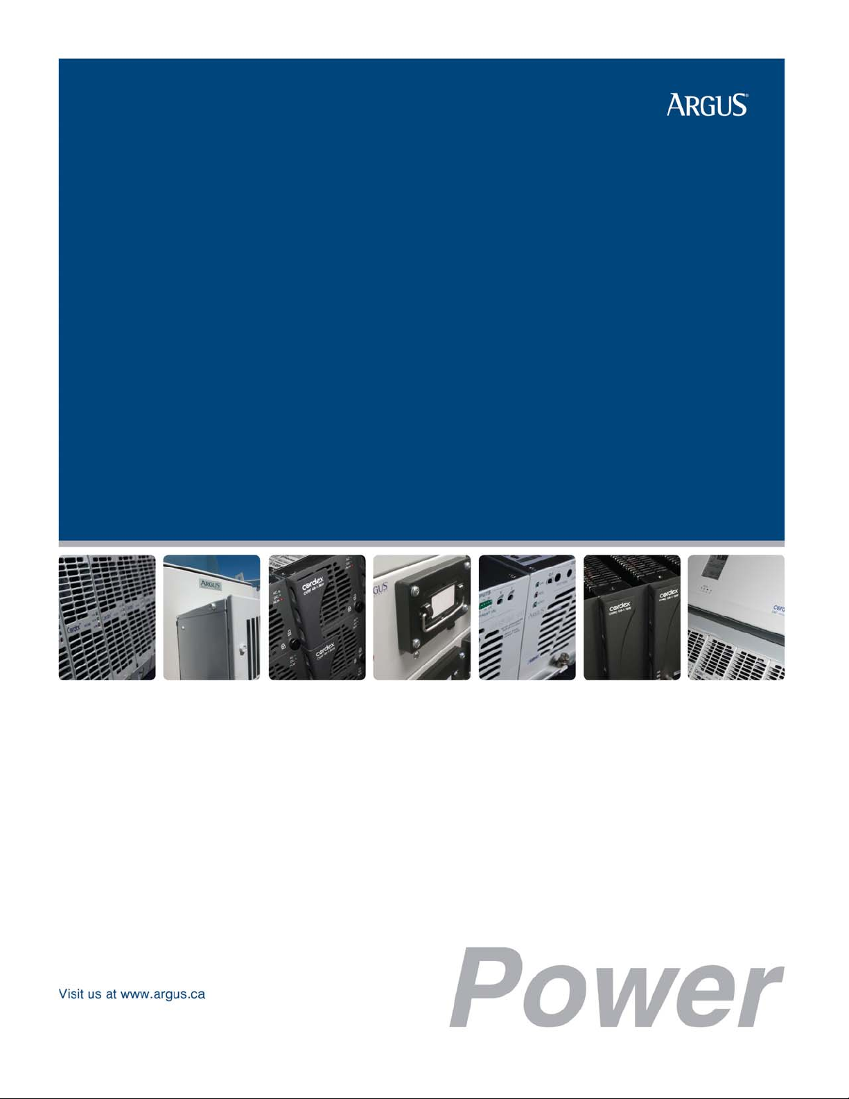
1.2 Product Overview
INEX inverter series is an integrated telecommunication AC power system, including inverter, static switch, LCD
controller, and interface modules. With versatile “building block” design and N+1 redundant configuration, INEX
inverter system facilitates complex telecommunication and industrial power demands.
INEX series DC to AC inverter module is available for 1000VA (800W) or 1500VA (1200W) to convert -48Vdc
input to 120Vac or 230Vac output at 50Hz or 60Hz. The inverter module is “hot swappable” meaning it can be
inserted or removed from the shelf without cutting power to or from the system.
A universal 19” shelf is designed to parallel connect and synchronize all INEX inverter models. With this shelf,
INEX series employs N+1 redundant configuration to output power maximum of 12kVA for 120Vac models and
18kVA for 230Vac models, and to operate in N+1 redundant mode for optimization. INEX “all master” dynamic
mechanisms automatically share and re-organize critical loads to further prevent interruption if one or more
inverter modules fail.
INEX selective static transfer switch (STS) provides automatic instantaneous load transfer, which further secures
uninterrupted operation of sensitive electronic equipment.
The INEX system controller, equipped with a DSP microprocessor, gives real-time system status through
comprehensive LCD/LED indication, and allows program settings through the display panel. A communication
interface module provides local or remote control and monitoring of the system.
Illustrations only and may not match your installation.
INEX Inverter system only
INEX Inverter system with
control/metering
Argus Technologies Ltd. 014-114-C0 Rev D WC
Printed in Canada. © 2008 Argus Technologies Ltd. ARGUS and INEX are registered trademarks of Argus Technologies Ltd. All Rights Reserved. Page 2 of 43
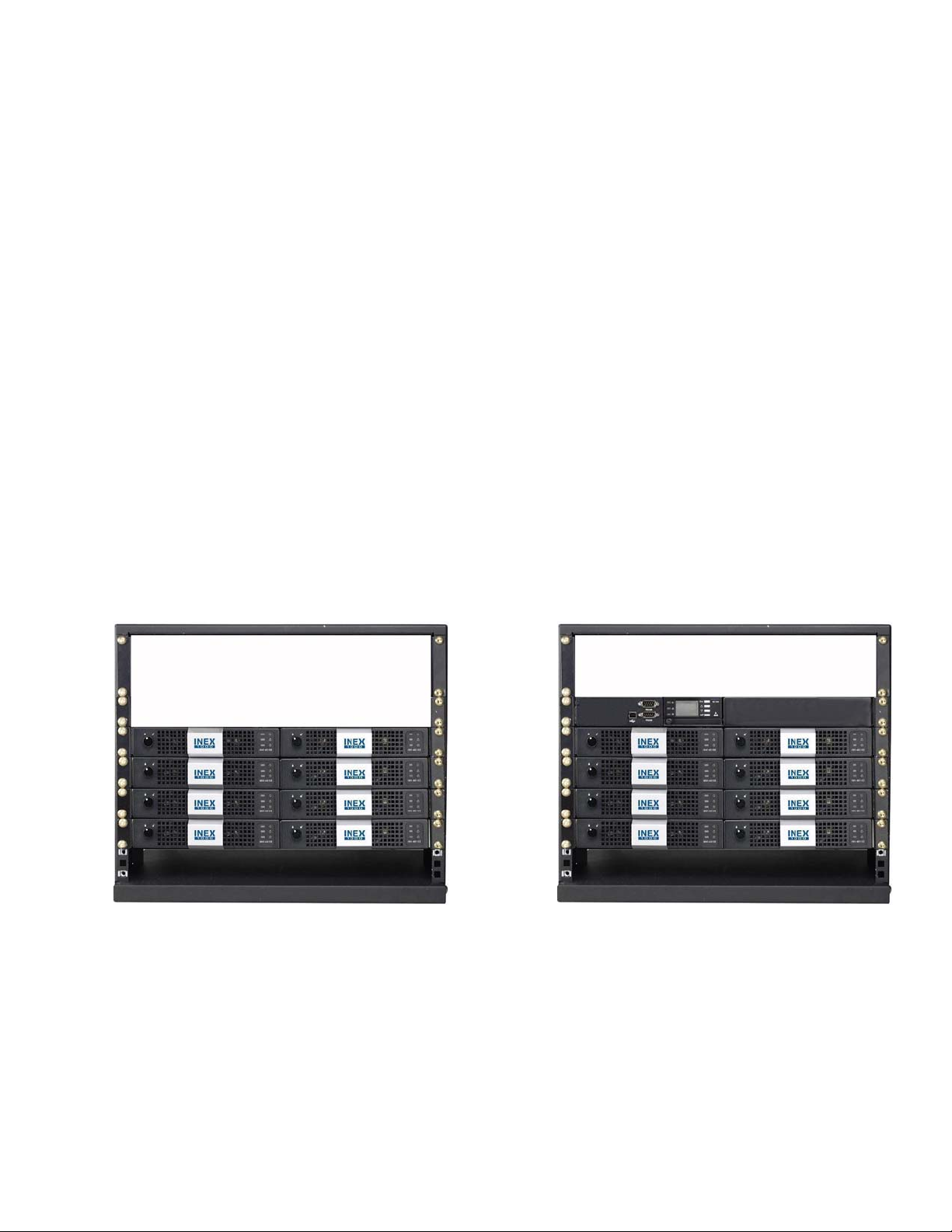
Illustrations only and may not match your installation.
INEX Inverter System features include:
• Pure sine wave output with low distortion
• Versatile module design allows a variety of configurations for different power needs
• Easily expands capacity up to 18kVA with N+1 redundancy
• “All master” dynamic mechanism eliminates single-point failure to optimize reliability
• Hot-pluggable connection allows module addition or removal without cutting power
• Ultimate high power density reducing space demand
• High efficiency (> 88%)
• Comprehensive LCD/LED display provides system status, and user-friendly panel eases program settings.
1.2.1 WinPower Software
WinPower is a power management software specifically designed to monitor and control the INEX inverter system
via a personal computer. It is available to download via the Argus website (www.argusdcpower.com).
To remotely monitor and control INEX inverters, connect the USB cable (A-B type) to the port on the front panel of
the interface module. Then follow instructions stated in the WinPower manual to properly install the software to a
personal computer physically connected to the INEX inverter system.
1.3 Model and Part Numbers
This product is available to order under the following part numbers:
UModel Number Description Part Number
INV-4810A 1000VA/800W inverter module (I/P: 48Vdc, O/P: 120Vac, 60Hz)......................014-114-10
INV-4810EA 1000VA/800W inverter module (I/P: 48Vdc, O/P: 230Vac, 50Hz)......................014-115-10
INV-4815A 1500VA/1200W inverter module (I/P: 48Vdc, O/P: 120Vac, 60Hz)....................014-116-10
INV-4815EA 1500VA/1200W inverter module (I/P: 48Vdc, O/P: 230Vac, 50Hz)....................014-117-10
MC-1000A Controller module................................................................................................018-593-10
STS-050A 50A static transfer switch module .......................................................................019-050-10
SMBSDU-50-2U-19AS Discontinued, see 020-424-10 ............................................................................S020-417-10S
MBSDU-50-2U-19-UA MBS+DU panel (maintenance bypass switch and NEMA AC distribution) ........020-422-10
MBSDU-50-2U-19A MBS+DU panel (maintenance bypass switch and IEC AC distribution).............020-424-10
INVSS-2EA-1U-19A Inverter shelf .......................................................................................................030-419-10
STSSS-I-1EA-1U-19A Controller/STS shelf (includes interface module IFC-1000NSA)........................030-420-10
MC-BLANK Controller blank plate ..........................................................................................614-616-10
IFC-BLANK Interface blank plate............................................................................................614-617-10
INV-BLANK Inverter/STS blank plate .....................................................................................614-618-10
The above information is valid at the time of publication. Consult factory for up-to-date ordering information.
INEX Inverter system with STS and
control/metering
INEX Inverter system with STS,
control/metering, and MBS/distribution

Argus Technologies Ltd. 014-114-C0 Rev D WC
Printed in Canada. © 2008 Argus Technologies Ltd. ARGUS and INEX are registered trademarks of Argus Technologies Ltd. All Rights Reserved. Page 3 of 43
2 Inspection
2.1 Packing Materials
All Argus products are shipped in rugged, double walled boxes and suspended via solid inserts to minimize shock
that may occur during transportation. Packaging assemblies and methods are tested to International Safe Transit
Association standards.
Power systems are also packaged with Cortex. This plastic wrap contains a corrosive-inhibitor that protects the
product from corrosion for up to two years.
2.1.1 Returns for Service
Save the original shipping container. If the product needs to be returned for service, it should be packaged in its
original shipping container. If the original container is unavailable, make sure the product is packed with at least
three inches of shock-absorbing material to prevent shipping damage.
NOTE: Argus Technologies is not responsible for damage caused by the improper packaging of returned products.
2.2 Check for Damage
Prior to unpacking the product, note any damage to the shipping container. Unpack the product and inspect the
exterior for damage. If any damage is observed contact the carrier immediately.
Continue the inspection for any internal damage. In the unlikely event of internal damage, please inform the
carrier and contact Argus Technologies for advice on the impact of any damage.
Verify that you have all the necessary parts per your order for proper assembly.
Argus Technologies Ltd. 014-114-C0 Rev D WC
Printed in Canada. © 2008 Argus Technologies Ltd. ARGUS and INEX are registered trademarks of Argus Technologies Ltd. All Rights Reserved. Page 4 of 43
3 Shelf Installation
This chapter is provided for qualified personnel to install the product.
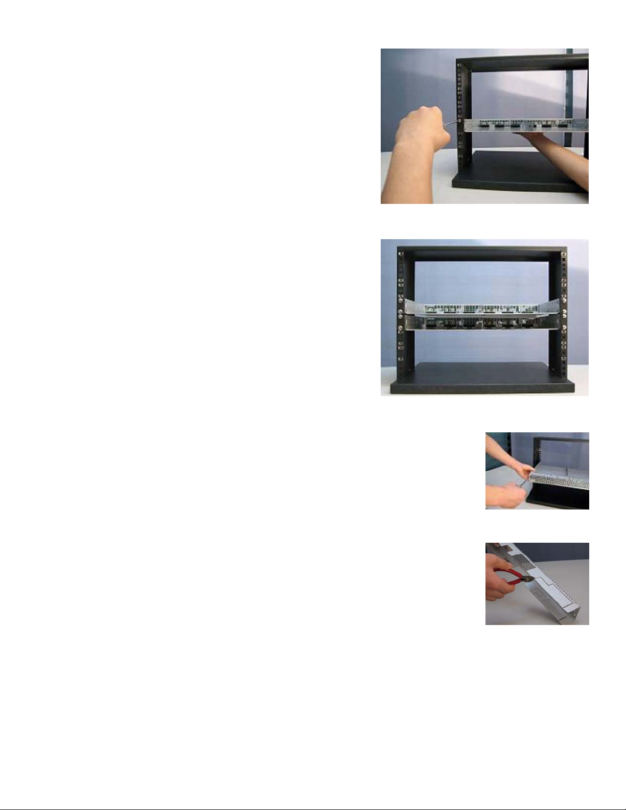
3.1 Inverter Shelf Preparation/Mounting
The inverter shelf has been designed for flush or mid-mounting in a 19” relay rack. Mounting brackets are also
supplied for mounting in a 23” rack.
NOTE: The shelf shall be mounted in a clean and dry environment. Allow at least 1.75” of free space in front of the unit
for unrestricted cooling airflow.
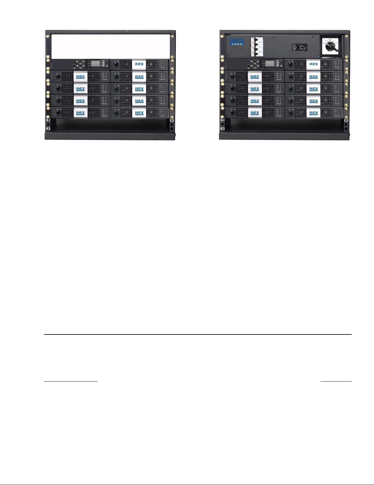
1. There are four holes right above three deck connectors of each inverter slot. Based on inverter model, insert
the supplied nylon guide pin to the corresponding hole:
• Position A for INV-4815A (as shown below)
• Position B for INV-4815EA
• Position C for INV-4810A
• Position D for INV-4810EA
CAUTION
System will fail to operate normally when inverter modules of different specifications are inserted
into inverter shelves. Use supplied nylon guide pins for securing only inverter modules of the
same specifications.
Nylon guide pins shown in Position A
B
C
D
B
C
D
Argus Technologies Ltd. 014-114-C0 Rev D WC
Printed in Canada. © 2008 Argus Technologies Ltd. ARGUS and INEX are registered trademarks of Argus Technologies Ltd. All Rights Reserved. Page 5 of 43
2. The shelf should be mounted to the rack using at least two
#12 – 24 x 1/2” screws in each bracket. Philips-type screws
and screwdriver should be used to eliminate the possibility of
slippage and scratching of the unit’s exterior. Washers (such
as internal tooth) or special screws that are designed to cut
through the painted surface should be used to ensure a good
chassis ground.
3. Put the inverter shelf into the equipment rack horizontally,
and align holes of mounting brackets and rack.
4. Each inverter shelf holds maximum two inverter modules.
Repeat the steps above to install the inverter shelves as
required.
5. All input and output connections are made through the knockouts, located in the top
and the bottom of the shelf rear cover, as well as both side panels.
Remove the rear cover to access the inverter shelf backplane and connectors.
6. Knockouts on top and bottom are for shelf inter-connections and supplementary wire
routing. To remove knockout, snip tabs, move plate up and down until tabs in back
snap apart.
Argus Technologies Ltd. 014-114-C0 Rev D WC
Printed in Canada. © 2008 Argus Technologies Ltd. ARGUS and INEX are registered trademarks of Argus Technologies Ltd. All Rights Reserved. Page 6 of 43
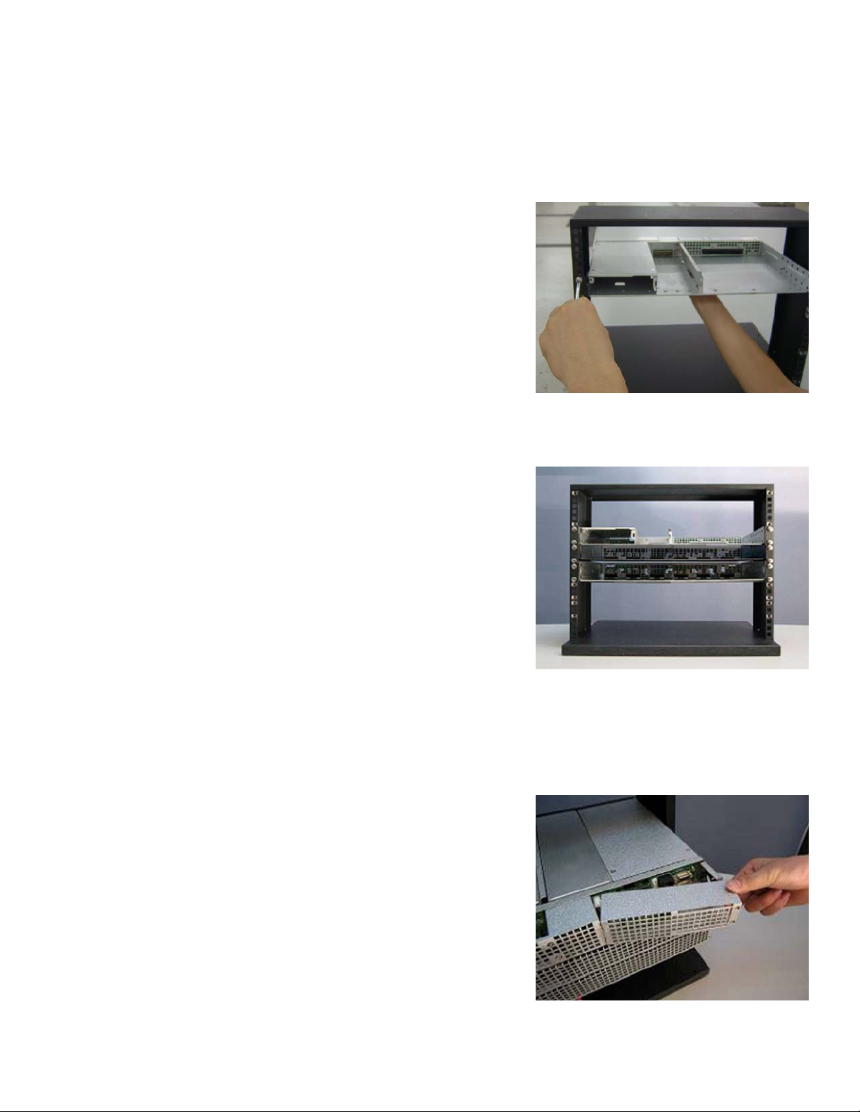
3.2 Controller/Interface/STS Shelf Mounting/Preparation
The shelf has been designed for flush or mid-mounting in a 19” relay rack. Mounting brackets are also supplied
for mounting in a 23” rack.
NOTE: The shelf shall be mounted in a clean and dry environment. Allow at least 1.75” of free space in front of the unit
for unrestricted cooling airflow.
1. The shelf should be mounted to the rack using at least two #12
– 24 x 1/2” screws in each bracket. Philips-type screws and
screwdriver should be used to eliminate the possibility of
slippage and scratching of the unit’s exterior. Washers (such as
internal tooth) or special screws that are designed to cut
through the painted surface should be used to ensure a good
chassis ground.
2. Put the shelf into the equipment rack horizontally, and align
holes of mounting brackets and rack.
NOTE: Each INEX controller module or interface module allows maximum
control of 12 inverter units cascaded. It is recommended to have the
controller/interface/STS shelf installed on top of stacked inverter
shelves to ease inter-connections; however, it may be installed
below the inverter shelves if the MBSDU panel is not required.
All input and output connections are made through the knockouts, located in the top and the bottom of each of the
two rear covers, as well as both side panels. The cover on the right is for the controller/interface section, and the
cover on the left is for the STS section.
3. Remove the rear cover(s) to access the shelf backplane and
connectors.
4. Knockouts on top and bottom are for shelf inter-connections. To
remove knockout, snip tabs, move plate up and down until tabs
in back snap apart.
Argus Technologies Ltd. 014-114-C0 Rev D WC
Printed in Canada. © 2008 Argus Technologies Ltd. ARGUS and INEX are registered trademarks of Argus Technologies Ltd. All Rights Reserved. Page 7 of 43
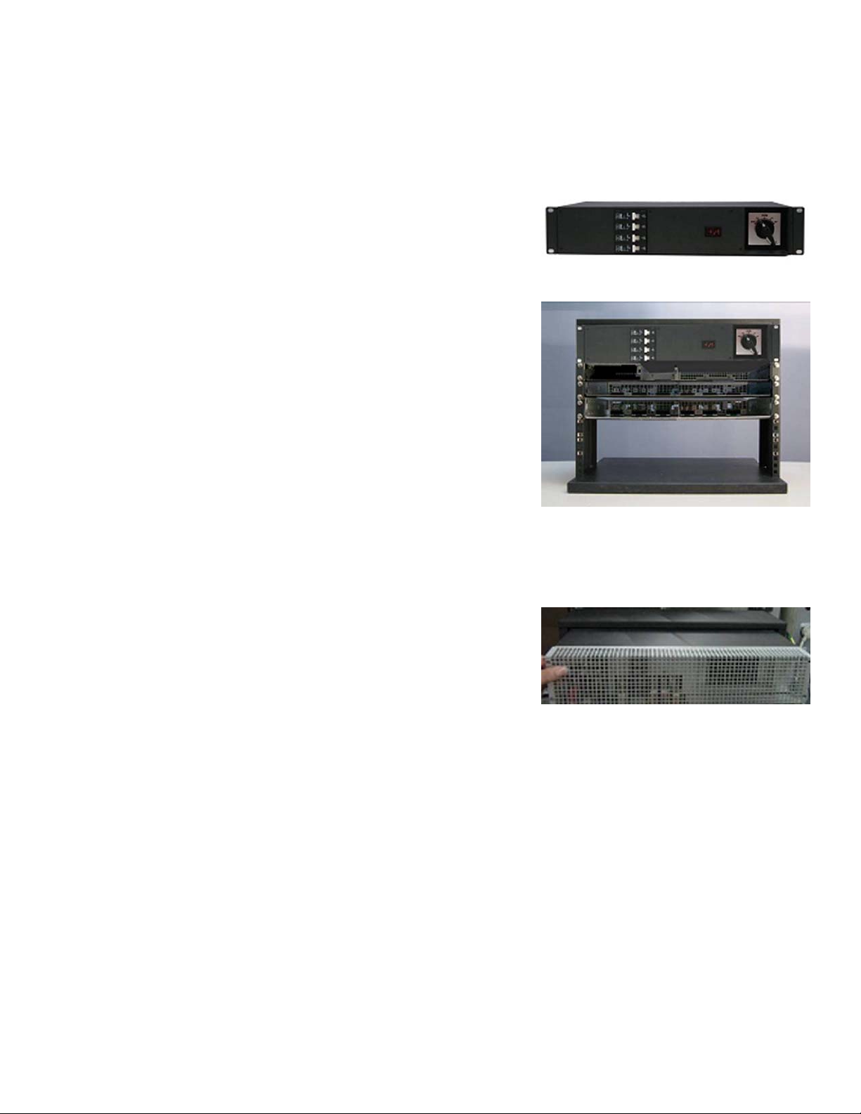
3.3 MBSDU Panel Mounting/Preparation
The panel has been designed for flush or mid-mounting in a 19” relay rack. Mounting brackets are also supplied
for mounting in a 23” rack.
NOTE: The panel shall be mounted in a clean and dry environment.
1. The panel should be mounted to the rack using at least two #12
– 24 x 1/2” screws in each bracket. Philips-type screws and
screwdriver should be used to eliminate the possibility of
slippage and scratching of the unit’s exterior. Washers (such as
internal tooth) or special screws that are designed to cut through
the painted surface should be used to ensure a good chassis
ground.
2. Put the panel into the equipment rack horizontally, and align
holes of mounting brackets and rack. The panel must be
mounted above the controller/interface/STS shelf.
3. All input and output connections are made through the knockouts, located in the bottom of the rear cover and
both side panels. To remove knockout, snip tabs, move plate up and down until tabs in back snap apart.
4. Remove the rear cover to access the backplane and connectors.
 Loading...