


APX Series |
® |
|
Non-standby Power Supply
APX Series
Installation and Operation Manual
Effective: April 2006
Alpha Technologies

PowerAlpha Technologies  ®
®

APX Series
Non-standby Power Supply
016-030-B0-005, Rev C
Effective Date: April 2006
Copyright© 2006
Alpha Technologies, Inc.
A Member of the Alpha Group
NOTE:
Photographs contained in this manual are for illustrative purposes only. These photographs may not match your installation.
NOTE:
Operator is cautioned to review the drawings and illustrations contained in this manual before proceeding. iIf there are questions regarding the safe operation of this powering system, please contact Alpha Technologies or your nearest Alpha representative.
NOTE:
Alpha shall not be held liable for any damage or injury involving its enclosures, power supplies, generators, batteries, or other hardware if used or operated in any manner or subject to any condition not consistent with its intended purpose, or is installed or operated in an unapproved manner, or improperly maintained.
Contacting Alpha Technologies: www.alpha.com
or
For general product information and customer service (7 AM to 5 PM, Pacific Time), call
1-800-863-3930,
For complete technical support, call
1-800-863-3364
7 AM to 5 PM, Pacific Time or 24/7 emergency support
016-030-B0-005, Rev. C |
3 |
Table of Contents
Safety Notes |
.......................................................................................................................... |
7 |
|
1.0 |
Introduction................................................................................................................. |
8 |
|
|
1.1 .......................................................................................... |
Operating Principle |
8 |
|
1.2 ................................................................................ |
Standard Con fi gurations |
10 |
|
1.3 .......................................................................................... |
Optional Features |
12 |
2.0 |
Installation................................................................................................................. |
14 |
|
|
2.1 ................................................................................. |
Pole Mount Installations |
14 |
|
..................................................................................... |
2.1.1 Wooden Poles |
14 |
|
................................................................... |
2.1.2 Concrete and Steel Poles |
15 |
|
2.2 ................................................................................. |
Wall Mount Installations |
16 |
|
2.3 .......................................................................... |
Pedestal Mount Installations |
17 |
|
2.4 ................................................................................ |
Rack Mount Installations |
20 |
|
2.5 ................................................................................ |
Shelf Mount Installations |
23 |
|
2.6 ................................................................................ |
Connecting Utility Power |
24 |
|
.................................................... |
2.6.1 Wiring the Enclosure Utility Service |
24 |
|
2.7 .......................................................................... |
External Service Disconnect |
27 |
|
2.8 .......................................................... |
Modular Transformer Assembly (MTA) |
29 |
|
2.9 ................................................................................... |
AC Output Connection |
31 |
|
2.10 ........................................................................................................... |
Options |
32 |
|
2.11 ............................................................. |
APX Output Voltage Recon fi guration |
39 |
3.0 |
Operation.................................................................................................................. |
40 |
|
|
3.1 ............................................................................................ |
Start - up and Test |
40 |
|
3.2 ......................................................................... |
Shutdown and MTA Removal |
41 |
4.0 |
Troubleshooting .....................................................................................and Repair |
42 |
|
|
4.1 ........................................................................................... |
Return Procedure |
42 |
|
4.2 ........................................................................................ |
Replacement Parts |
43 |
5.0 |
Specifi ............................................................................................................cations |
44 |
|
|
5.1 ............................................................................................ |
APX Schematics |
44 |
|
5.2 .................................................................................... |
Speci fi cations for APX |
46 |
4 |
016-030-B0-005, Rev. C |
|
List of Figures |
|
Fig. 1-1, |
Ferroresonant “Tank” Circuit and Resulting Output Waveform .............................................. |
9 |
Fig. 1-2, |
Pole Mount Enclosure ........................................................................................................... |
11 |
Fig. 1-3, APX Main Transformer Assembly.......................................................................................... |
11 |
|
Fig. 1-4, The Alpha APX (PM) and Installable Options1..................................................................... |
13 |
|
Fig. 2-1, APX Enclosure Pole Mounting ............................................................................................. |
15 |
|
Fig. 2-2, |
Wall Mount Installation ......................................................................................................... |
16 |
Fig. 2-3, |
Stake Mounting Installed in PED.......................................................................................... |
17 |
Fig. 2-4, |
PED Enclosure ..................................................................................................................... |
18 |
Fig. 2-5, |
Soil-mount PED Enclosure Installed in Poured Concrete .................................................... |
18 |
Fig. 2-6, |
Concrete Pad Mounting........................................................................................................ |
19 |
Fig. 2-7, APX Rack Mount (120VAC Version)..................................................................................... |
20 |
|
Fig. 2-8, |
Option Placement and Power Connections.......................................................................... |
21 |
Fig. 2-9, APX-E Rack Mount (230VAC Version) ................................................................................. |
21 |
|
Fig. 2-10, |
Shelf Mount (SM) ............................................................................................................... |
22 |
Fig. 2-11, PED-M, PWE or UPE Enclosure Mounting ....................................................................... |
23 |
|
Fig. 2-12, PED-M, PWE or UPE Enclosure Mounting ....................................................................... |
23 |
|
Fig. 2-13, APX Bottom View ............................................................................................................... |
24 |
|
Fig. 2-14, 120VAC/60Hz Wiring.......................................................................................................... |
25 |
|
Fig. 2-15, APX 230VAC/50Hz Wiring.................................................................................................. |
26 |
|
Fig. 2-16, |
Service Entrance/Meter Connections, 120VAC.................................................................. |
28 |
Fig. 2-17, |
Service Entrance/Meter Connections, 240VAC.................................................................. |
28 |
Fig. 2-18, MTA Mounted on Baseplate Assembly of PM Enclosure ................................................... |
30 |
|
Fig. 2-19, |
Universal Bracket for PED-mount ...................................................................................... |
30 |
Fig. 2-20, |
Cable Connector/Output Port Assembly............................................................................. |
31 |
Fig. 2-21, |
SIL-C Installed in Baseplate ............................................................................................... |
32 |
Fig. 2-22, |
LA-M Inserted into Receptacle Box ................................................................................... |
33 |
Fig. 2-23, |
LA-P Inserted into Receptacle............................................................................................ |
33 |
Fig. 2-24, LA-E Option (230VAC models) Mount Under Receptacle Box........................................... |
34 |
|
Fig. 2-25, |
LA-E Installation ................................................................................................................. |
35 |
016-030-B0-005, Rev. C |
5 |
List of Figures, continued |
|
Fig. 2-26, AMM-C Ammeter Kit .......................................................................................................... |
36 |
Fig. 2-27, AMM-C Install Steps........................................................................................................... |
36 |
Fig. 2-28, AMM-C Installation ............................................................................................................. |
37 |
Fig. 2-29, TDR-M Potentiometer ........................................................................................................ |
37 |
Fig. 2-30, TDR-M and ACAT-3P Options Installed in the APX............................................................ |
38 |
Fig. 2-31, ACAT-3P and TDR-M Installed in the APX Rack Mount..................................................... |
38 |
Fig. 3-1, APX Circuit Breaker and Fuse Location............................................................................... |
40 |
Fig. 3-2, Shutdown and MTA Removal ............................................................................................... |
41 |
Fig. 4-1, APX Schematic..................................................................................................................... |
44 |
Fig. 4-2, APX 90V Schematic ............................................................................................................. |
45 |
|
List of Tables |
|
Table 1-1, |
Standard Features ............................................................................................................. |
10 |
Table 1-2, |
Optional Features .............................................................................................................. |
12 |
Table 2-1, |
High-Magnetic Breakers for Square D Service Entrances................................................. |
27 |
Table 2-2, APX Output Voltage Reconfiguration................................................................................. |
39 |
|
Table 4-1, |
Troubleshooting Guide....................................................................................................... |
42 |
Table 4-2, |
Replacement Parts ............................................................................................................ |
43 |
Table 5-1, APX Series Specifications ................................................................................................. |
46 |
|
6 |
016-030-B0-005, Rev. C |

Safety Notes
Review the drawings and illustrations contained in this manual before proceeding. If there are any questions regarding the safe installation or operation of the system, contact Alpha Technologies or the nearest Alpha representative. Save this document for future reference.
To reduce the risk of injury or death, and to ensure the continued safe operation of this product, the following symbols have been placed throughout this manual. Where these symbols appear, use extra care and attention.
ATTENTION:
The use of ATTENTION indicates specific regulatory/code requirements that may affect the placement of equipment and installation procedures.
NOTE:
A NOTE provides additional information to help complete a specific task or procedure.
CAUTION!
The use of CAUTION indicates safety information intended to PREVENT DAMAGE to material or equipment.
 WARNING!
A WARNING presents safety information to PREVENT INJURY OR DEATH to the technician or user.
016-030-B0-005, Rev. C |
7 |
1.0 Introduction
The Alpha APX Series Non-standby Power Supply provides conditioned power to signal amplifiers in cable television and broadband distribution systems. The modular design, consisting of a baseplate, transformer assembly and enclosure cover, supplies the load with current-limited, regulated AC power, that is free from spikes, surges and other forms of power line transients. The design supports easy upgrades simply by replacing the transformer assembly, saving time and money.
Alpha’s non-standby power supplies are extremely efficient, with a typical efficiency rating of 90% or better.
The versatile APX Series includes an AC input circuit breaker, output fuse, *output receptacle, VSF fitting, and external grounding clamp and can be mounted on poles, walls, racks, shelves, or pedestals. Operator controls are inside the enclosure on the main transformer assembly.
You can equip the APX with various options, including a *Time Delay Relay (TDR-M), Plug-in Lightning Arrestor (LA-M), Status Indicator LED (SIL-C), plug-in *Amp-Clamp (ACAT-3P), *Ammeter (AMM-C), and Enclosure Security Lock (GLK). See Section 1.3 for a complete description of all available options
1.1Operating Principle
The Alpha Modular Transformer Assembly (MTA) contains the ferroresonant transformer, resonant circuit capacitor, and control panel with line input circuit breaker and output fuse assembly.
The Ferroresonant Transformer
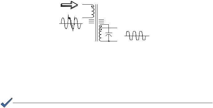
Alpha APX Series uses ferroresonant transformer technology to provide line conditioning and voltage regulation. The primary and secondary windings of the transformer are physically isolated from each other by a large steel core which significantly reduces the capacitive coupling of spikes and noise to the secondary winding. This provides a regulated, currentlimited output with excellent isolation and noise attenuation, (120dB common mode and 60dB transverse mode).
Another unique feature of the ferroresonant transformer is its ability to provide current limiting in the event of a short circuit. This effect is called foldback. The transformer’s output current can typically reach 150% of the nameplate output current rating for a short period of time without damage to the transformer. When the transformer reaches the saturation point, the output current will decrease (foldback on itself) to a minimum value, and thereby provide current limiting. Designs based on ferroresonant transformer are extremely rugged and reliable offering many years of trouble-free operation.
The Resonant Circuit Capacitor
An oil-filled resonant AC capacitor is connected to the resonant (secondary) winding of the transformer forming a tank circuit. This provides the resonant circuit function which
contributes to the voltage regulation of the supply. The advantage of this type of transformer/ capacitor design is the ability of the ferroresonant transformer to regulate its output voltage over a wide range of input voltages and output loading. Typical output voltages may vary
+/- 3% to 5%, with input voltages variations of +/- 15% of nominal line voltage, and output loading of 20% to 100%. This tight regulation is advantageous in cable television applications as the active devices are protected from dangerous voltages fluctuations.
8 |
016-030-B0-005, Rev. C |
1.0Introduction, continued
1.1 Operating Principle, continued
T1
Ferroresonant Transformer and AC Capacitor
Noisy Input Waveform |
C1 |
Clean Output Waveform
Fig. 1-1, Ferroresonant ‘Tank’ circuit and resulting output waveform
AC power enters the module where it is converted to a “quasi” square wave and regulated (at the required output voltage). It is then passed on to the load via the VSF fitting located on the baseplate assembly.
NOTE:
A true RMS voltmeter must be used to correctly measure the output voltages.
016-030-B0-005, Rev. C |
9 |

1.0Introduction, continued
1.2Standard Configurations
The APX Series non-standby power supplies are available in the following configurations:
Available Configurations |
Description |
APX 6008 |
120VAC, 60Hz Input; 8A, 480VA, 60V Output; available in |
|
Pole, Rack, Wall, Shelf, or Pedestal Mount configurations. |
|
Includes: 8A thermal input circuit breaker, 120VAC output |
|
receptacle and 10A output fuse. |
APX 6014 |
120VAC, 60Hz Input; 14A, 840VA, 60V Output; available in |
|
Pole, Rack, Wall, Shelf, or Pedestal Mount configurations. |
|
Includes: 12A thermal input circuit breaker, 120VAC output |
|
receptacle and 15A output fuse. |
APX 6008 E |
230VAC, 50Hz Input; 8A, 480VA, 60 or 48V Output; |
|
available in Pole, Rack, Wall, Shelf, or Pedestal Mount |
|
configurations. Includes: 8A thermal input circuit breaker, |
|
230VAC output receptacle and 10A output fuse |
APX 6014 E |
230VAC, 50Hz Input; 14A, 840VA, 60 or 48V Output; |
|
available in Pole, Rack, Wall, Shelf, or Pedestal Mount |
|
configurations. Includes: 12A thermal input circuit breaker, |
|
230VAC output receptacle and 15A output fuse. |
APX 4808 E |
230VAC, 50Hz Input; 8A, 384 VA, 48V Output; available in |
|
Pole, Rack, Wall, Shelf, or Pedestal Mount configurations. |
|
Includes: 8A thermal input circuit breaker, 230VAC output |
|
receptacle and 10A output fuse. |
APX 6008 P |
220VAC, 60Hz Input; 8A, 480VA, 60V Output; available in |
|
Pole, Rack, Wall, Shelf, or Pedestal Mount configurations. |
|
Includes: 8A thermal input circuit breaker, 120VAC output |
|
receptacle and 10A output fuse. |
APX 6014 P |
220VAC, 60Hz Input; 14A, 840VA, 60V Output; available in |
|
Pole, Rack, Wall, Shelf, or Pedestal Mount configurations. |
|
Includes: 12A thermal input circuit breaker, 120VAC output |
|
receptacle and 15A output fuse |
APX 9015 |
120VAC, 60Hz Input; 15A, 60, 75 or 90V Output; |
|
available in Pole, Rack, Wall, Shelf, or Pedestal Mount |
|
configurations. Includes: 20A thermal input circuit breaker, |
|
120VAC output receptacle and 20A output fuse |
APX 9015 |
240VAC, 60Hz Input; 15A, 60, 75 or 90V Output; available |
|
in available in Pole, Rack, Wall, Shelf, or Pedestal Mount |
|
configurations. Includes: 10A thermal input circuit breaker, |
|
240VAC output receptacle and 20A output fuse. |
Table 1-1, Standard Configurations
10 |
016-030-B0-005, Rev. C |
1.0Introduction, continued
1.2 Standard Configurations, continued
Main Transformer Assembly
(MTA)
Enclosure
 Cover
Cover
Baseplate
Assembly
Holes for 
Padlock
Fig. 1-2, Pole Mount Enclosure
Fig. 1-3, APX Main Transformer Assembly
016-030-B0-005, Rev. C |
11 |

1.0Introduction, continued
1.3Optional Features
You can equip the APX Series with the following options.See Section 2.10, for installation instructions.
Option |
Description |
Part Number |
GLK |
Security lock for pole mount enclosures. PM models are |
GLK-PED: 740-263-22; |
Enclosure Locks |
equipped with a security hole to accomodate a standard |
GLK-PM: 744-229-21 |
|
padlock. |
|
LA-M |
The LA-M is a 350 joule, Metal Oxide Varistor (MOV) for |
LA-L120V: 744-173-20; |
Plug-in Lightning Arrestor |
primary site protection. It provides protection from voltage |
|
|
spikes caused by lightning and other disturbances. The |
LA-E240V: 744-174-20 |
LA-E (230VAC) |
LA-M is enclosed in plastic housing and plugs directly into |
|
|
a dedicated receptacle, eliminating the need for additional |
LA-P+120V:020-098-24 |
|
wiring. |
LA-M120V: 020-116-21 |
|
|
|
|
LA-E housed in an aluminum enclosure and must be hard |
(x2 for 240V) |
|
wired into the APX. |
|
SIL-C |
Indicates that the APX is supplying AC output to the load |
740-239-21 |
Status Indicator LED |
and can be viewed from outside the enclosure. The light |
|
|
(red) remains ON as long as power is present at the |
|
|
modules output. |
|
The following options are available for the APX Series power supplies only |
||
AMM-C |
Displays the output current to the load. It is also useful as a |
10A : |
Ammeter |
status indicator: a zero reading indicates no output current |
740-238-21 |
|
is being drawn by the load, a pegged meter indicates a |
|
|
short circuit condition in the plant. |
15A : |
|
|
740-238-22 |
|
|
15A: |
|
|
(9015 only) |
|
|
744-594-20 |
TDR-M |
In the event of a AC utility line outage and subsequent |
60V: |
Plug-in Time Delay Relay |
voltage return, the TDR-M delays power to the output for 10 |
020-114-21 |
|
to 60 seconds, thereby providing time for the line voltage |
|
|
to stablize and reducing possible noise spikes and other |
90V: |
|
transients. |
020-114-23 |
ACAT-3P |
Protects active and passive equipment from voltage surges |
60V: |
Plug-in Amp Clamp |
and transients. Provides “Crowbar” clamping protection |
020-115-21 |
|
from voltage spikes in excess of 104V. |
|
|
Consists of two rugged SCR’s (silicon controlled rectifiers) |
90V: |
|
020-115-23 |
|
|
connected in an inverse parallel configuration with a steady |
|
|
state current of 35A and a one cycle (8 ms) pulse rating of |
|
|
500A. The SCR’s are triggered into conduction whenever |
|
|
the Amp Clamp’s bidirectional trigger diodes senses the |
|
|
presence of voltage transients exceeding 104-115V peak |
|
|
threshold. The fast response trigger circuit gates the |
|
|
appropriate SCR ON (in nanoseconds) to shunt the surge |
|
|
current to ground, effectively protecting sensitive equipment |
|
|
from transient overvoltage conditions. |
|
|
|
|
Table 1-2, Optional Features
12 |
016-030-B0-005, Rev. C |
1.0Introduction, continued
1.3Optional Features, continued
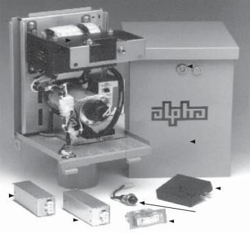
See Table 1-1 for a complete description of these features.
Modular |
|
|
|
|
|
|
|
|
|
|
|
|
|
|
|
|
|
|
|
|
|
Transformer |
|
|
|
|
|
|
|
|
|
|
Assembly (MTA) |
|
|
|
|
|
|
|
|
GLK |
|
|
|
|
|
|
|
|
|
|
|
|
|
|
|
|
|
|
|
|
|
Enclosure |
|
|
|
|
|
|
|
|
|
|
Locks |
|
|
|
® |
|
|
||||||
|
|
|
|
|
|
|
|
|
|
Enclosure |
|
|
|
|
|
|
|
|
|
|
|
|
|
|
|
|
|
|
|
|
|
Cover |
ACAT-3P |
|
|
|
|
|
|
|
|
|
LA-M |
|
|
|
|
|
|
|
|
|
||
|
|
|
|
|
|
|
|
|
SIL-C |
|
TDR-M |
|
|
|
|
|
|
|
|
|
|
|
|
|
|
|
|
|
|
|
||
|
|
|
|
|
|
|
|
|
AMM-C |
|
|
|
|
|
|
|
|
|
|
||
|
|
|
|
|
|
|
|
|||
|
|
|
|
|
|
|
|
|
|
|
|
|
Fig. 1-4, The Alpha APX (PM) and Installable Options |
||||||||
016-030-B0-005, Rev. C |
13 |

2.0Installation
2.1 Pole Mount Installations
The APX-PM can be mounted on wooden, steel, or concrete poles. Most local codes require that the base of the enclosure be at a minimum height from the ground. Always verify height restrictions before proceeding.
NOTE:
Poles are typically the property of the local utility. The utility must approve both the location and the method used to mount the APX before installation.
NOTE:
Before installing the MTA, verify that all options have been installed and properly connected.
2.1.1 Wooden Poles
For wooden poles, use mounting bolts that completely penetrate the pole.
Materials Required:
•Two (2) 5/8" diameter machine bolts (UNC thread) SAE Grade 5 or better, length to suit pole
•Four (4) 5/8" diameter zinc-plated flat washers
•Two (2) 5/8" diameter hex nuts (UNC thread)
Tools Required:
•Auger or drill for boring 3/4" diameter holes through the wooden pole
•Associated sockets or wrenches
Procedure:
1.Remove the APX from the shipping container and set the unit on its back (mounting bracket down).
2.Loosen the enclosure front panel hold-down screw and tilt the cover forward. Remove the cover by sliding it (at the hinges) to the right.
3.Loosen the captive screw at the bottom of the baseplate. Lift the Modular Transformer assembly up and off of the baseplate. Set the MTA aside.
4.Mark the position for the upper mounting bolt on the utility pole. Drill a 3/4" hole completely through the pole.
5.Using the baseplate as a template, align the upper hole in the baseplate with the upper hole in the utility pole. Verify that the spacing between the marks is 4 1/2" center to center. Drill the lower mounting hole.
6.Place a flat washer on each bolt and insert the mounting bolts through the baseplate assembly and pole.
7.Secure both bolts using a 5/8" washer and nut. Tighten nuts until the flanges on the baseplate mounting bracket dig into the wood approximately 1/4".
8.Install the Modular Transformer Assembly (MTA) onto the baseplate (see Section 2.8).
14 |
016-030-B0-005, Rev. C |

2.0Installation, continued
2.1 Pole Mount Installations, continued
Service Drop
5/8" Diameter Bolts and
Associated Hardware
4 1/2” center-center
To Service
Entrance
Enclosure Mounting Bracket
APX Enclosure
NOTE: If mounting to a steel or concrete pole, use these two strap slots
VSF Output Connector
Cable Output
Utility Power Input
(from Service Entrance)
#8 AWG (Minimum)
Copper Ground Wire
Fig. 2-1, APX Enclosure Pole Mounting
2.1.2 Concrete and Steel Poles
Materials Required:
Two (2) 1-1/2" approved mounting straps, length to suit pole.
Tools Required:
Assorted sockets or wrenches
Procedure:
1.Mark the position for the upper mounting strap on the utility pole.
2.Run two approved 1-1/2" mounting straps through the mounting bracket located on the back of the baseplate assembly.
3.Center the baseplate assembly on the pole and tighten the mounting straps.
4.Install the Modular Transformer Assembly (MTA) onto the baseplate (see Section 2.8 for details).
016-030-B0-005, Rev. C |
15 |
 Loading...