


950-265-10 Rev E (02/2010)
Cordex Controller Software
Version 2.0
034-136-B2
The following documents and drawings are included in this manual to provide the necessary information required for routine operation:
• Program License Agreement: |
048-556-10 |
• Operation Instructions: |
034-136-C0 |
Alpha Technologies Ltd. |
034-136-B2 Rev C WC |
Printed in Canada. © 2010 Alpha Technologies Ltd. ALPHA and CORDEX are trademarks of Alpha Technologies Ltd. All Rights Reserved.
CONTENTS
1 |
INTRODUCTION ............................................................................................................................................................. |
4 |
|
|
1.1 |
Scope of the Manual ..................................................................................................................................... |
4 |
|
1.2 |
User Interface (see Chapter 4) ..................................................................................................................... |
4 |
|
1.3 |
Software Overview ........................................................................................................................................ |
5 |
2 |
QUICK START............................................................................................................................................................... |
9 |
|
|
2.1 |
Applying Startup Power................................................................................................................................. |
9 |
|
2.2 |
Remote Communications (see Chapter 9).................................................................................................... |
9 |
|
2.3 |
Trouble-shooting Tips ................................................................................................................................... |
9 |
3 |
STANDARD FEATURES................................................................................................................................................ |
10 |
|
|
3.1 |
Password Security ...................................................................................................................................... |
10 |
|
3.2 |
Software Configuration Loading and Updates ............................................................................................ |
10 |
|
3.3 |
Mixed Rectifier System ............................................................................................................................... |
10 |
|
3.4 |
Safe Voltage................................................................................................................................................ |
10 |
|
3.5 |
Power Save................................................................................................................................................. |
10 |
|
3.6 |
Battery Temperature Compensation........................................................................................................... |
11 |
|
3.7 |
Battery Auto Equalization............................................................................................................................ |
12 |
|
3.8 |
Battery Monitor and Charge Current Control .............................................................................................. |
12 |
|
3.9 |
Low Voltage Disconnect Operation............................................................................................................. |
13 |
|
3.10 |
Signals Management .................................................................................................................................. |
13 |
|
3.11 |
Statistics and Historical Data ...................................................................................................................... |
13 |
4 |
OPERATION................................................................................................................................................................ |
15 |
|
|
4.1 |
Startup and Reset Procedure ..................................................................................................................... |
15 |
|
4.2 |
Normal Operation........................................................................................................................................ |
15 |
|
4.3 |
Mode Status (active area) and Temp Comp Indication .............................................................................. |
17 |
|
4.4 |
Rectifiers (and Converters) Information (active area)................................................................................. |
21 |
|
4.5 |
Analog Signals Display (active area) .......................................................................................................... |
22 |
|
4.6 |
Alarm Indication (active area) ..................................................................................................................... |
23 |
|
4.7 |
Argus Icon (active area).............................................................................................................................. |
24 |
|
4.8 |
Date and Time (active area) ....................................................................................................................... |
26 |
|
4.9 |
Saving Settings ........................................................................................................................................... |
26 |
|
4.10 |
Overview of Web Interface.......................................................................................................................... |
27 |
5 MENU NAVIGATION AND SAMPLE PROGRAMMING ........................................................................................................ |
29 |
||
|
5.1 |
Menu Navigation ......................................................................................................................................... |
29 |
|
5.2 |
Basic Programming Example...................................................................................................................... |
30 |
|
5.3 |
Advanced Programming.............................................................................................................................. |
30 |
i
6 |
MENU STRUCTURE, PROGRAMMING AND ADJUSTMENTS .............................................................................................. |
32 |
|
|
6.1 |
System Info ................................................................................................................................................. |
32 |
|
6.2 |
Converters................................................................................................................................................... |
35 |
|
6.3 |
Rectifiers ..................................................................................................................................................... |
36 |
|
6.4 |
Batteries ...................................................................................................................................................... |
39 |
|
6.5 |
Alarms ......................................................................................................................................................... |
46 |
|
6.6 |
Signals......................................................................................................................................................... |
58 |
|
6.7 |
Controls....................................................................................................................................................... |
78 |
|
6.8 |
Communications ......................................................................................................................................... |
80 |
|
6.9 |
Hardware..................................................................................................................................................... |
83 |
|
6.10 |
Logs & Files (Web Interface only)............................................................................................................... |
84 |
|
6.11 |
Supervisor ................................................................................................................................................... |
86 |
7 |
ADVANCED PROGRAMMING ........................................................................................................................................ |
87 |
|
|
7.1 |
Example: Customize ................................................................................................................................... |
87 |
|
7.2 |
Equation Builder Keypads........................................................................................................................... |
87 |
|
7.3 |
Tips on Programming.................................................................................................................................. |
88 |
8 |
CXC COMMUNICATIONS MENU PARAMETERS.............................................................................................................. |
89 |
|
|
8.1 |
Ethernet Port Configuration ........................................................................................................................ |
89 |
|
8.2 |
PPP Connection Devices............................................................................................................................ |
90 |
|
8.3 |
Rear Port Configuration .............................................................................................................................. |
91 |
9 |
REMOTE COMMUNICATIONS ........................................................................................................................................ |
93 |
|
|
9.1 |
Establishing a Network Connection via a Crossover Cable........................................................................ |
93 |
|
9.2 |
PPP Serial Data Connection....................................................................................................................... |
94 |
|
9.3 |
Modem Connection ................................................................................................................................... |
100 |
10 |
SIMPLE NETWORK MANAGEMENT PROTOCOL (SNMP).............................................................................................. |
102 |
|
|
10.1 |
Overview ................................................................................................................................................... |
102 |
|
10.2 |
Network Manager MIB Files...................................................................................................................... |
104 |
|
10.3 |
Communication Configuration................................................................................................................... |
105 |
11 |
FACTORY RANGES AND DEFAULTS ........................................................................................................................... |
109 |
|
12 |
MODBUS® COMMUNICATIONS PROTOCOL ................................................................................................................. |
114 |
|
13 |
TROUBLE-SHOOTING ................................................................................................................................................ |
120 |
|
|
13.1 |
Technical Support ..................................................................................................................................... |
120 |
14 |
ALPHA CONVENTIONS .............................................................................................................................................. |
121 |
|
|
14.1 |
Numbering System.................................................................................................................................... |
121 |
|
14.2 |
Acronyms and Definitions ......................................................................................................................... |
121 |
INDEX ............................................................................................................................................................................. |
|
122 |
|
ii
TABLES |
|
Table A–Output channel assignments............................................................................................................................ |
48 |
Table B–Digital input channel assignments ................................................................................................................... |
50 |
Table C–Analog input channel assignments .................................................................................................................. |
59 |
Table D–Controller signal default definitions.................................................................................................................. |
62 |
Table E–Rectifiers menu defaults................................................................................................................................. |
109 |
Table F–Signals menu defaults .................................................................................................................................... |
109 |
Table G–Batteries menu defaults ................................................................................................................................. |
110 |
Table H–Converters menu defaults.............................................................................................................................. |
110 |
Table I–Alarms menu defaults...................................................................................................................................... |
111 |
Table J–Controls menu defaults................................................................................................................................... |
112 |
Table K–Communications menu defaults..................................................................................................................... |
113 |
Table L–Hardware menu defaults ................................................................................................................................ |
113 |
Table M–Supervisor menu defaults.............................................................................................................................. |
113 |
Table N–CXC Modbus PDU address definition for function code 0x01 (read coils) .................................................... |
114 |
Table O–CXC Modbus PDU address definition for function code 0x02 (read discrete inputs).................................... |
118 |
Table P–CXC Modbus PDU address definition for function code 0x03 (read holding registers) ................................. |
119 |
Table Q–CXC Modbus PDU address definition for function code 0x04 (read input registers) .................................... |
119 |
Table R–Trouble-shooting guide .................................................................................................................................. |
120 |
iii
Refer to the back of this manual for Factory Service and Technical Support contact information
1 Introduction
1.1Scope of the Manual
This document describes the software features, on-site setup and operation of the Cordex System Controller (CXC) from Alpha Technologies.
Refer to the Installation manual for hardware details.
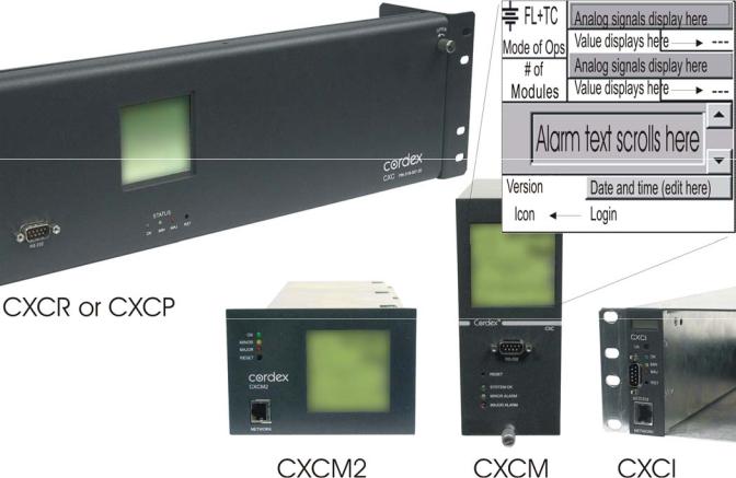
1.2User Interface (see Chapter 4)
Located on the front panel of each CXCM (or CXCP or CXCR) model is a 160-x-160-pixel touch screen liquid crystal display (LCD) similar to that used in a personal digital assistant (PDA), see Figure 1. This graphical user interface (GUI) enables a person to interact with screen selectable items.
For CXC models with a touch screen display, the use of a PDA type stylus is recommended and may be required when accessing the on-screen keyboard for some adjustments.
Figure 1–CXC models showing features of main menu touch screen
The CXC will provide feedback during operation with different audible tones for alarms, invalid password, and menu navigation.
NOTE: Other models, such as the CXCI, only have a 4-digit display for monitoring system voltage and current. Without a touch screen display, system setup and management is performed exclusively with the web interface, see Section 4.10.
CAUTION
Do not connect anything other than the Alpha modem and Alpha-supplied DB-9 cable to the D-sub port on the front of the CXCI.
A step by step connection wizard – provided to establish remote communications with the CXC – is available via the Alpha website (www.alpha.ca).
Alpha Technologies Ltd. |
034-136-C0 Rev B WC |
Printed in Canada. © 2010 Alpha Technologies Ltd. ALPHA and CORDEX are trademarks of Alpha Technologies Ltd. All Rights Reserved. |
Page 4 of 122 |
Visit the Alpha website at www.alpha.ca for the latest manual and product downloads
1.3Software Overview
The CXC software controls the entire DC power system. Features include temperature compensation, auto equalization, remote access, battery diagnostics, and web server and SNMP support.
1.3.1New Features since version 1.2
The following changes/updates have been incorporated into version 1.3 of the CXC software:
Communications Protocol Selection – enables the Supervisor to set the communications protocol for either the Cordex series (CAN) or Pathfinder series (RS-485).
E-mail – enables communication of alarms via Ethernet or modem.
Enhancements to Battery Features – enables live Battery Discharge parameters to be viewable via Battery Log.
Enhancements to Event Logging & Statistics – provides tracking of several parameters on a daily basis, such as battery current information.
Equation Builder for Custom Alarms & Signals – enables the Supervisor to program separate triggering equations into the CXC software. The equations may reference any combination (up to 16) of the analog inputs, digital inputs, virtual inputs, and alarms (such as Fan Fail) utilizing logical and arithmetic arguments that simulate the functionality of a programmable logic controller (PLC).
Modem Support – expanded for web connections via PPP using modem (internal or external) with CXCP or CXCR models.
Third Language Support – provides for multiple language files; which can be uploaded via web interface.
1.3.2New Features since version 1.3
The following changes/updates have been incorporated into version 1.4 of the CXC software:
220Vdc System Support – enables the Supervisor to select the system voltage as 24V, 48V or 220Vdc.
CAN Communications Protocol – expanded to include Alpha’ new Cordex Shunt Multiplexer.
Web Interface Additions – provides submit (changes) button on top of every page, data logging, LVD countdown timer, and relay text labels can be edited.
1.3.3New Features (since version 1.4)
The following changes/updates have been incorporated into version 1.5 of the CXC software:
Urgent AC Mains Fail Alarm – provides indication of alarm condition. This major alarm has a time delay; the default activation value is ten (10) minutes.
AC Phase Voltage Measurement – enables assignment (mapping) of rectifiers to a phase for individual phase voltage readings.
SNMP Trap Dial-out – enables dialup connection from CXC to SNMP manager PC over intranet via corporate intranet RAS (remote access server) port. This setup is similar to an e-mail RAS client.
1.3.4New Features (since version 1.5)
The following changes/updates have been incorporated into version 1.6 of the CXC software:
CXCI Support – enables connectivity with Alpha’ new CXCI (controller used in small power Cordex integrated rectifier systems) where system setup is performed with the CXC web interface alone.
IP Address Reset – provides a means to reset the IP address of a CXC without a touch screen display.
SNTP Support – enables synchronization of device time with an external source (see www.NTP.org).
LCD Touch Screen Calibration – enables user to fine-tune the accuracy of the touch screen on site.
Default Values for Dynamic (Editable) Text Files – may be restored to factory settings.
Calibrate Analog Inputs – feature has been improved for web interface.
Alpha Technologies Ltd. |
034-136-C0 Rev B WC |
Printed in Canada. © 2010 Alpha Technologies Ltd. ALPHA and CORDEX are trademarks of Alpha Technologies Ltd. All Rights Reserved. |
Page 5 of 122 |
Refer to the back of this manual for Factory Service and Technical Support contact information
1.3.5New Features since version 1.6
The following changes/updates have been incorporated into version 1.7 of the CXC software:
12Vdc System Support – enables the Supervisor to select the system voltage as 12, 24, 48, 125 or 220Vdc.
Mixed Rectifier System – enables the use of one type of Alpha Pathfinder model rectifier working in parallel with one type of Alpha Cordex model rectifier; e.g. PFM 48V-10kW with CXRF 48-3.6kW. The menu item Rectifier Protocol is no longer required and has been removed.
Safe Voltage – enables the Supervisor to set the default system voltage (Safe Mode) in the event that communications to Cordex rectifiers should fail.
Site Number – provides an additional line of text under Contact Information for convenient display of the Site Number.
Rectifier Report Enhancements – provides new columns for device name and percentage of maximum output current (per rectifier).
Battery Information – provides an additional window to enter/view the manufacturer’s data for the batteries in the system; e.g., for inventory purposes.
Alarm Configuration Screen Enhancements – provides a list of all alarms in one place (via web browser). The configuration of most alarms may be done on this one screen.
Alarm Tone – enables the Supervisor to enable/disable the audible alarm buzzer (tone). Battery Test Alarm – provides a warning to indicate that a Battery Test is in progress.
Invalid Battery Voltage Alarm – provides for indication of invalid battery charging voltage; e.g., in the event that the sense leads have become disconnected.
SNMP Enhancements – provides SNMP/Severity level (numeric) and enables CXC supervisor to set the scheme.
AC Mains Voltage Correction – provides the means to apply a correction factor to the reading coming from the rectifier.
ADIO Enhancements – enables the Supervisor to configure individual signals for an ADIO (Analog Digital Input Output) Device; i.e., Cordex Smart Peripherals.
Custom Signal Units – enables the Supervisor to set the units value for Custom Signals; e.g., V, AH, mm, etc.
LVD DOD Control – enables the Supervisor to configure each LVD control for activation once the percentage of Depth of Discharge (DOD) has increased above a threshold.
SNMP Community Settings – enables the Supervisor to configure CXC SNMP community settings. SNMP Trap Recovery – enables the CXC SNMP agent to hold traps in a buffer during a network block out.
Event Notifications – Multiple SNMP and SMTP Destinations – enables the Supervisor to add up to eight (8) separate destinations for SNMP and SMTP dial-out or e-mail notifications.
Test Relays – provides a message of warning to the CXC operator before allowing the toggling of an LVD relay and allows the user to cancel the operation.
Argus MIB File Enhancements – provides separate object identifier (OID) for active and cleared alarm traps. Alarm status and signals are reconstructed into tables and sub tables to allow for future expansion while remaining backward compatible with already defined alarms and signals.
Log File Cleanup – provides improved event log file management by filtering and condensing repetitive rectifier events on a daily basis. File retrieval has been updated for sorting by name and by chronological order. The display of log information has also been improved for ease of user navigation.
Passwords for Supervisor and User – provides two levels of password protection – the same password cannot be used for both Supervisor and User.
1.3.6New Features (since version 1.7)
The following changes/updates have been incorporated into version 1.8 of the CXC software:
Configuration File Enhancements – enables the Supervisor to exclude settings and groups of settings when applying changes. A partial configuration file may be generated and sent to CXC (v1.81 and above).
CXCI Modem Support – enables connectivity to the CXCI’s new front D-sub port with the Alpha modem and Alpha-supplied DB-9 cable.
Alpha Technologies Ltd. |
034-136-C0 Rev B WC |
Printed in Canada. © 2010 Alpha Technologies Ltd. ALPHA and CORDEX are trademarks of Alpha Technologies Ltd. All Rights Reserved. |
Page 6 of 122 |
Visit the Alpha website at www.alpha.ca for the latest manual and product downloads
1.3.7New Features (since version 1.8)
The following changes/updates have been incorporated into version 1.9 of the CXC software:
Web Interface Facelift – provides more efficient access to software features. Speed/responsiveness has been improved over previous version (testing has shown up to four times faster). Each page can be accessed individually; for example, users with slow interfaces, such as modem, do not have to navigate to specific pages as before.
Modbus® Support – enables CXC communication of alarms and live signals in RTU encoded data format using Modbus protocol (messaging structure developed by Modicon®) upon query via TCP to any Modbus supervisor or master.
Remote Battery Test Mode – enables the Supervisor to define a condition (custom alarm) that will force a transition to battery test mode once the condition is met. BT mode stays active as long as the condition remains true. This feature is exclusive for the Cordex series of rectifiers.
ADIO Support for 4R/8D I/O Module – allows configuration of this new module in the digital alarms or custom alarm sections of the menus; where the alarm condition can be associated with a digital input and mapped to a relay. The 4R/8D I/O module is a Cordex Smart Peripheral designed to expand the CXC I/O by four output relays and eight digital inputs.
Temp Comp in EQ Mode (enable/disable) – allows the supervisor to enable or disable automatic battery temperature compensation in equalize mode independently from float mode.
Boost Mode – provides the supervisor with the means to equalize charge the battery at a higher voltage relative to the connected load. Activation is manual and certain conditions must be met to prevent damage to the load.
Custom/User Alarms – have increased in number from 5 to 20.
Battery Log – provides support for very slow discharges. This is accomplished by saving intermediate battery log information in the event of controller power loss before battery recharge completes.
1.3.8New Feature for version 1.93
ADIO Support for Cordex Battery Monitor System (BMS) – enables connectivity with Alpha’ new BCMC module – a Cordex Smart Peripheral – designed to monitor a number of voltages, currents and temperatures in battery strings via a number of remote devices that are managed through a ring data network. Configuration is performed in the signals section of the CXC’s menus.
1.3.9New Feature for version 1.95
Simplified BCT EQ Threshold – from rate of change to an absolute current value.
The BC Rate of Change setting used to be the rate of change of battery current in units of A/H. This setting has changed and is now BC Threshold in units of A.
NOTE: When upgrading to v1.95 or later, users of the BCT EQ feature must re-evaluate the BC Threshold setting and enter a new value since the units of the setting has changed.
1.3.10New Feature for version 1.97
Cordex DC-DC Converter (CXD) Support – enables the Supervisor to configure converter settings, display and read analog values; similar to the system controller features applied to the Cordex rectifier series.
The converter defaults will be based on the system voltage if it is either 24 or 48Vdc.
NOTE: At present, the converter software does not support:
Two types of converters simultaneously
12, 125, and 220Vdc systems.
Other features include:
|
Active voltage control |
|
Firmware upgrade |
|
Loadsharing |
|
Converter locate |
|
Inventory update |
|
Major and minor alarms |
Alpha Technologies Ltd. |
034-136-C0 Rev B WC |
Printed in Canada. © 2010 Alpha Technologies Ltd. ALPHA and CORDEX are trademarks of Alpha Technologies Ltd. All Rights Reserved. |
Page 7 of 122 |
Refer to the back of this manual for Factory Service and Technical Support contact information
1.3.11New Features (since version 1.97)
The following changes/updates have been incorporated into version 2.0 of the CXC software:
Counters and Timers – counters enable the Supervisor to monitor the number of times a particular event occurs. Timers are used to measure the amount of time since an event occurred or the amount of time between two events. These features are suitable for general-purpose signals that can be used in Custom Signal or Custom Alarm equations.
Dynamic Current Limit – enables the Supervisor to change the battery current limit based on the status of a digital input; such as, when powering a system with a generator, to limit battery recharge current to prevent the generator from overloading. See Dynamic Charge Current Control (CCC) feature.
ALCO Enhancements – enables the user to silence the alarms for a set duration (in minutes). The user may also enable or disable cutoff of each of the following when ALCO is pressed:
Audible alarm
Alarm relays
SNMP.
Printable Configuration (Config) – enables the user to print the total CXC configuration (for a particular controller) via a Print button on the Logs&Files > Manage Configuration File page.
Equipment Inventory – a new User Inventory page allows the user to enter up to twenty inventory items. Additionally, a System Inventory page enables the user to view a single list of all CAN connected devices, user inventory items and battery information items. Previously, devices would only be shown on the individual category pages; e.g., rectifiers connected shown on the Rectifier section.
SNMP Related Features – is comprised of these new items:
Add Trap Acknowledge (Inform)
CXC will wait for SNMP Manager (software) to acknowledge that it has received a trap. If the manager does not acknowledge within a certain amount of time, the trap will be resent.
Timestamp Varbind
Data added to the SNMP trap to indicate the time of the event that triggered the trap to be sent.
Alarm Trigger Varbind
Data added to the SNMP trap that shows the analog value that triggered an alarm activation or deactivation.
Multiple Community Strings
The user may enter more than one set of SNMP community strings. This is to permit multiple SNMP NMS programs, with different community strings, to connect to the CXC. A company with multiple NMS's, each in a different region, with a different community string, will find it easier to connect to the CXC from various places.
Static Calibration – enables the Supervisor to calibrate Controller analog inputs and ADIO (except BCMC) analog inputs without the need for a live signal at the input; especially useful for calibrating current inputs for systems in the field.
Scheduler – enables the Supervisor to use the system time and date as operands in custom alarm and signal equations.
Modbus® and SNMP – additions were made for converter alarms and signals.
1.3.12New Features since version 2.03
The following changes/updates have been incorporated into version 2.04 of the CXC software:
The battery log will be closed off when 96 hours has elapsed since the start of the recharge cycle. This is in addition to the existing functionality that closes off the log when the returned AH reaches 115% of the rated capacity during the recharge cycle.
Improved response of charge current control when lithium-ion batteries are installed. Lithium-ion batteries are detected by scanning the battery information and looking for the keyword “lithium” or “li-ion” in the model comment fields.
The rectifier start delay algorithm now allows a setting of 0 s instead of the former minimum of 1 s.
Alpha Technologies Ltd. |
034-136-C0 Rev B WC |
Printed in Canada. © 2010 Alpha Technologies Ltd. ALPHA and CORDEX are trademarks of Alpha Technologies Ltd. All Rights Reserved. |
Page 8 of 122 |
Visit the Alpha website at www.alpha.ca for the latest manual and product downloads
2 Quick Start
2.1Applying Startup Power
1.Initiate startup routine by applying power to the CXC; e.g. close battery breaker or close converter and rectifier input and output breakers.
NOTE: The CXC will perform a short self-test as it boots up. Alarm alerts are normal. The LEDs perform a scrolling pattern to indicate there is activity. Please wait.
2.Check and adjust alarms and control levels in the CXC’s submenus.
3.Check and adjust group settings in the CONVERTERS and RECTIFIERS submenus; e.g. float, equalize voltage, etc.
4.Verify COMMUNICATIONS settings as needed.
5.Program the CXC’s TEMP COMP and AUTO EQUALIZE settings as needed.
6.Test relay OUTPUT ALARM\CONTROLS as needed; e.g. Major Alarm, CEMF, etc.
2.2Remote Communications (see Chapter 9)
The CXC can be set up, monitored and tested with a RS-232 serial data connection, ETHERNET 10/100 Base-T or over a phone line using a modem. Some standard scenarios are described below:
Network (TCP/IP secured by user) to CXC rear Ethernet port.
Computer to CXC via RS-232 serial data connection (PPP) using a null modem cable connected to the Craft port (front panel RS-232).
Laptop to CXC via direct Ethernet connection using a standard crossover cable.
External modem to CXC via RS-232 serial data connection using a straight through cable connected to the rear RS-232 port.
Internal modem (see ordering options).
CAN bus (located next to the Ethernet port) is provided for connection to the Cordex series of converters and rectifiers.
RS-485 bus provides a secondary connection for products (e.g., Pathfinder rectifiers) that do not support the CAN bus interface.
2.3Trouble-shooting Tips
See Trouble-shooting chapter for more information.
2.3.1Converter and Rectifier Tips
The Cordex Converter (CXD) Rectifier (CXR) series modules are plug and play. When a CXD or CXR module is added to the system, the CXC will detect and update the inventory automatically.
If CXD or CXR module communication has failed, or a module has been removed from the system, an INVENTORY UPDATE1 must be initiated manually.
For the Pathfinder series of rectifiers, ensure that the:
Rectifiers are in NORMAL OPERATING MODE
REMOTE ACCESS is ENABLED
REMOTE ADJUST is ENABLED
BAUD RATE is set to 9600 baud.
2.3.2Cordex Controller Tips
Use the CXC GUI (Section 4.2) or web interface (4.10) to ensure that the operating levels (e.g. input/output voltage, converter voltage, etc.) are within operating parameters of alarm and control thresholds.
1 Should Inventory Update fail: a) check cable & connections; b) check settings under System Info/System Configuration for correct voltage.
Alpha Technologies Ltd. |
034-136-C0 Rev B WC |
Printed in Canada. © 2010 Alpha Technologies Ltd. ALPHA and CORDEX are trademarks of Alpha Technologies Ltd. All Rights Reserved. |
Page 9 of 122 |
Refer to the back of this manual for Factory Service and Technical Support contact information
3 Standard Features
The CXC provides centralized setup, control and monitoring of a communications power system.
3.1Password Security
Two levels of password security are available: User and Supervisor. The same password cannot be used for both.
User access (Section 4.7.1) enables navigation through menus, but no changes are permitted.
Supervisor access enables navigation and changes to parameters including Supervisor password, see 6.11.1. The Supervisor may change the User password only via the web interface.
3.2Software Configuration Loading and Updates
Factory software updates and adjustments to the configuration file are possible through the RS-232 serial port or Ethernet connection. The Supervisor may exclude settings and groups of settings when applying changes. A partial configuration file may also be generated and sent to CXC (v1.81 and above).
3.3Mixed Rectifier System
The CXC enables the use of one type of Alpha Pathfinder model rectifier working in parallel with one type of Alpha Cordex model rectifier; for example, PFM 48V-10kW or PFM 48V-3kW with CXRF 48-3.6kW. Another example is PFM 24V-3kW with CXRF 24-3.1kW. The menu item Rectifier Protocol is no longer required and has been removed. The load share of each rectifier is based on the percentage of maximum output current of the rectifier; see Rectifier Report (4.4.2). In some cases, e.g. battery test algorithm, the system functionality will be limited to that of the Pathfinder rectifiers while the communications will equal that of the Cordex controller.
NOTE: The Pathfinder rectifiers will not be shown under Upgrade Firmware as that submenu applies to Cordex rectifiers and smart peripherals only.
3.4Safe Voltage
Safe Voltage is the voltage that the rectifiers will default to if the controller fails. In general terms, the open circuit voltage for VRLA batteries is determined to be a point where discharge or over charge will not occur.
The Supervisor can set the default system voltage (Safe Mode) in the event that communications to Cordex rectifiers should fail. This feature has a time delay (a function of the rectifier); the activation value is five (5) minutes. The rectifier manual lists the default parameters.
3.5Power Save
This feature will enable the Supervisor to improve operational efficiency when conditions warrant by running only the necessary number of rectifiers. For example, when the load is significantly less than the available system power, the controller will shut down one or more of the rectifiers so that the remaining rectifiers may operate with greater efficiency at a higher current level. A short (one-minute) time delay or hysteresis is included to avoid nuisance alarming and to eliminate changes if the load is fluctuating.
In addition, with Power Save, rectifiers are rotated into use on a weekly basis to share the service time.
When Power Save is enabled, it takes effect when a minimum discharge or load current (~2.5% of maximum current of one rectifier) is achieved.
Charge or battery current limit calculations are made based on rectifiers that are running.
The Power Save feature is suspended during Battery Test mode, see 4.3.4.6.
NOTE: The remote shutdown setting (Cordex series only) enables the function in the rectifier. The Power Save feature uses this functionality when a Cordex rectifier is commanded to shut down.
The Power Save feature does not work with the Alpha RSM 48/100 series of rectifiers.
Alpha Technologies Ltd. |
034-136-C0 Rev B WC |
Printed in Canada. © 2010 Alpha Technologies Ltd. ALPHA and CORDEX are trademarks of Alpha Technologies Ltd. All Rights Reserved. |
Page 10 of 122 |
Visit the Alpha website at www.alpha.ca for the latest manual and product downloads
3.6Battery Temperature Compensation
The automatic battery temperature compensation (Temp Comp or TC) will function with Cordex series rectifiers that support CAN bus communications and Pathfinder series rectifiers that support RS-485 remote communications.
Temp Comp may be active in either float (4.3.1) or equalize (4.3.2) mode.
Temperature inputs are available on the CXC for monitoring a lead acid battery string. Temperature sensor readings can be displayed on the GUI in either Celsius (°C) or Fahrenheit (°F) scales.
The CXC will have the flexibility to display the breakpoints in voltage as well as temperature, also enabling them to be entered as voltage or temperature.
The detection of thermal runaway will be limited to a programmable Battery Over Temperature Alarm. This will enable the Supervisor to select a temperature that will trigger an alarm.
3.6.1Theory of Battery Temperature Compensation
Battery life expectancy and performance is directly related to battery ambient temperature. The optimum temperature for battery operation is 25°C (77°F). Without compensation, battery life is seriously compromised at temperatures above 25°C, while battery performance is reduced below it.
Adjusting the battery’s float or equalize voltage to correspond with temperature fluctuations will ensure maximum battery performance and life expectancy. With the CXC, this may be accomplished by using the software’s built-in automatic temperature compensation function.
This function works by adjusting the system, every ten minutes, as the temperature changes and provides for a maximum voltage change of 0.1V over this interval.
While this may seem like a small voltage change, even if the battery had a temperature compensation slope as high as 5.5mV per C, the CXC would still be able to track a temperature change in the battery of up to 4.5 C or 8 F per hour. Due to the large thermal mass of the battery string, even an extreme rise or drop in environmental temperature would be very unlikely to cause this kind of temperature change in the battery over a one hour period.
Temp Comp occurs at standard rates commonly referred to as slope-compensation settings. For maximum performance, it’s important to match the battery slope compensation with the setting recommended by the battery manufacturer. This is not to be confused with slope regulation; which refers to the process of regulating current among a group of parallel-operating rectifiers.
The Temp Comp feature has programmable breakpoints. These are the points at which Temp Comp will cease. Further temperature decreases or increases will NOT increase or decrease the output voltage. This protects the connected load from excessive voltage conditions. As Temp Comp is active in either float or equalize mode, breakpoints should be set with this in mind.
The Temp Comp feature also incorporates fail-safe circuitry to prevent it from driving the rectifier system to a voltage higher than is suitable for the load or battery.
3.6.2Operation of Battery Temperature Compensation
The CXC can accommodate up to four sensors for lead acid battery temperature monitoring. If more than one probe is used and the temperature readings are within 5°C (9°F) of one another, the temperature readings will be calculated for the average. If the readings difference exceeds 5°C, it is assumed that thermal runaway is occurring in one battery string and the calculation changes from average to the highest reading. If any reading is suddenly outside the norm (i.e. cut leads or open leads), that reading is discarded and the associated Temp Sensor Fail alarm is issued. The temperature calculation will then return to the average of the remaining sensors, or next highest reading.
Temp Comp has been programmed as a low priority item; all commands and operations will take precedence over Temp Comp. If a command is issued during a Temp Comp cycle, the cycle will be put on hold until the command is completed. If any operation is happening when the Temp Comp cycle occurs, the cycle will be put on hold until the operation is completed. Temp Comp will resume when the command or operation is completed.
The Temp Comp feature can be enabled or disabled in the CXC’s Batteries menu.
Alpha Technologies Ltd. |
034-136-C0 Rev B WC |
Printed in Canada. © 2010 Alpha Technologies Ltd. ALPHA and CORDEX are trademarks of Alpha Technologies Ltd. All Rights Reserved. |
Page 11 of 122 |
Refer to the back of this manual for Factory Service and Technical Support contact information
3.7Battery Auto Equalization
Auto Equalize (Auto-EQ) is a protective feature designed to ensure optimal lead acid battery life and performance. With the CXC, auto equalize is used for two basic purposes: first, for providing a quick battery recharge after an AC power failure, and second, as a long-term battery maintenance solution.
Refer to the battery manufacturer’s recommendations for equalization charging.
3.7.1Battery Charge Auto Equalize
Battery Charge Auto Equalize can be used after a prolonged AC power failure, when the battery voltage has decreased to a low level.
Once the batteries have decreased beyond the auto equalize low voltage threshold, the CXC will enter an armed mode. When AC power returns, the system voltage begins to increase, which charges the batteries.
Once the system voltage increases to the high voltage threshold, the CXC enters the equalize mode and begins to equalize charge the batteries for a period specified by the Supervisor in the AUTO-EQ DURATION submenu. This is done to ensure the EQ duration is not effectively reduced by the time it takes to recharge the battery back to the nominal system voltage.
3.7.2Periodic Auto Equalize
Periodic Auto Equalize can be used for maintaining the long-term integrity of a battery string. Over time, individual battery cell voltages may vary greatly. As a result, to ensure that batteries remain in optimum condition, they should be equalize charged at regular intervals. The CXC enables the Supervisor to program the time between automatic equalize charging of the battery string in the AUTO-EQ INTERVAL submenu.
3.7.3Battery Current Termination (BCT) Equalize
The BCT Equalize feature provides an alternative method of ending EQ mode early to prevent over-charging of the battery. Once enabled, it will only be active when EQ mode is caused by a Charge Auto Equalize.
BCT EQ will terminate Charge Auto EQ when the battery current falls below the BC Threshold setting. Upon initial activation of EQ mode – that is triggered by the Charge Auto EQ feature – the CXC will wait for one minute of system stabilization time before monitoring the battery current for BCT EQ. After one minute, the battery current is checked about once per second to see if the current has fallen below the BC Threshold.
When the battery current falls below the BC Threshold, and remains below the threshold for three seconds, the EQ duration is replaced with the BCT duration. After this time, the system returns to FL mode.
3.8Battery Monitor and Charge Current Control
The Battery Monitor feature enhances the CXC’s capability to provide information about the battery to the User. Charge Current Control will help increase battery longevity by keeping the battery current to within specified limits.
Charge current to the battery during recharge will be limited to a value as programmed by the Supervisor. This value will be derived from the battery manufacturer’s specification sheet and entered by the Supervisor.
A battery run time prediction will be performed while the battery is supplying power to the load. The CXC will collect data to estimate the time it will take the battery to be drained. If the Battery Monitor feature is enabled and the battery is sourcing current to the load, a time estimate appears in the Mode Status screen. Runtime estimate is also available in the Analog Signals display, which can be enabled for display status in (SIGNALS) CONFIGURE SIGNALS\CONTROLLER SIGNALS.
During an AC outage or Battery Test, data will be collected to calculate a capacity prediction. A capacity of 80% means the battery is due to be replaced. The accuracy of this will improve as the battery undergoes more discharge cycles.
Alpha Technologies Ltd. |
034-136-C0 Rev B WC |
Printed in Canada. © 2010 Alpha Technologies Ltd. ALPHA and CORDEX are trademarks of Alpha Technologies Ltd. All Rights Reserved. |
Page 12 of 122 |
Visit the Alpha website at www.alpha.ca for the latest manual and product downloads
3.9Low Voltage Disconnect Operation
Whenever the system parameters require that the LVD be activated, a 60-second countdown and audible warning will commence. When the countdown reaches zero, the LVD will be activated. During this countdown, an icon on the GUI may be pressed to evoke a prompt to inhibit LVD controls – activated by entering the Supervisor password. There is a 10-minute time-out for this. See also LVD Inhibit 6.7.2.
3.10Signals Management
The CXC enables the Supervisor to view and edit a signal equation of the selected signal. The Supervisor may also configure custom signals; properties may be modified or disabled as required. All signals in the system can be selected for a signal equation builder making it possible to combine logic conditions and analog values to generate an alarm.
The Supervisor can select which Temperature Sensor (including any smart peripheral temperature sensors) is enabled for Battery Temp Sensor Signal.
3.11Statistics and Historical Data
The CXC is capable of tracking several statistical parameters on a daily basis; e.g., analog statistics or triggered items (listed below), such as, battery log and event log, see Data Logging (web interface only), Section 6.6.3.
Data is stored in local memory and may be accessed via a web interface. The logged data is comma-delimited such that it can be automatically viewable in rows and columns in MS Excel. The data is stored on a first-in-first- out basis.
3.11.1 Analog Statistics
All statistics, to a maximum of 90 records (one per day) contain a time stamp and date. Daily analog statistics include the minimum, maximum and average of:
Load Voltage |
Load Current |
Battery Voltage |
Battery Current |
AC Mains |
Battery Temperature |
Total Rectifier Current |
Average DC Voltage |
Average AC Voltage |
Number of Acquired Rectifiers |
Number of Sourcing Rectifiers |
Ten Custom Signals |
3.11.2Battery Log
A maximum of 40 records can be logged for battery statistics and events. The Battery Log contains the following:
Event Type |
Capacity Rating |
Battery Test Start Time |
Depth of Discharge |
Discharge Duration Time |
Capacity |
Amp Hours Delivered |
Recharge Duration |
Amp Hours Recharge Return |
Peukert Number |
1-5 Max. Midpoint Deviation Discharge |
Data1 |
1-5 Max. Midpoint Deviation Recharge |
Data2 |
Battery Current/Average Battery Current |
Battery Temperature/Average Battery Temperature |
Battery Voltage/Battery Test End Voltage |
Open Circuit Voltage |
Battery Test Result |
|
During a battery discharge, active battery log information is displayed in a row above the Battery Log. This information is then no longer available after the battery has finished recharging.
The Battery Log also provides support for very slow discharges. This is accomplished by saving intermediate battery log information in the event of controller power loss before battery recharge completes.
When a battery test (BT) is started by the remote BT feature, the battery log will show “Remote BT” in the Event Type column.
Alpha Technologies Ltd. |
034-136-C0 Rev B WC |
Printed in Canada. © 2010 Alpha Technologies Ltd. ALPHA and CORDEX are trademarks of Alpha Technologies Ltd. All Rights Reserved. |
Page 13 of 122 |
Refer to the back of this manual for Factory Service and Technical Support contact information
3.11.3Event Log
In addition, the CXC can record up to 500 events. All events are stamped with the date and time. Some of the events available include the following:
All alarm events (activation and deactivation),
Rectifier alarm details,
Any change of state of the digital inputs,
Other miscellaneous events; such as, rectifiers being turned off or on due to the Power Save feature.
3.11.4Data Logging
This feature of the CXC web interface allows the user to perform complex/custom configurations of the data gathered by the Alpha controller. Various ways of setting the log frequency/limit and start/stop triggers enables greater management of the events for collection.
The data is stored in files showing the records associated with each for easy archiving and retrieval. File Save Option enables a FIFO (first in first out) or “Stop when full” means of data collection.
Recommended size is up to seven signals and a maximum one thousand entries, as very large log files may not be viewable. If the datalog screen comes up blank, the log is too large to be displayed.
Alpha Technologies Ltd. |
034-136-C0 Rev B WC |
Printed in Canada. © 2010 Alpha Technologies Ltd. ALPHA and CORDEX are trademarks of Alpha Technologies Ltd. All Rights Reserved. |
Page 14 of 122 |
Visit the Alpha website at www.alpha.ca for the latest manual and product downloads
4 Operation
4.1Startup and Reset Procedure
When the CXC is powered-up or reset, it will first perform a 15-second self-test before displaying the Cordex logo and various identification messages. The three front-panel LED’s will illuminate temporarily, but will extinguish after the system has finished its self-test. Next, the GUI will display the power system’s parameters during Normal operating mode, see Figure 2.
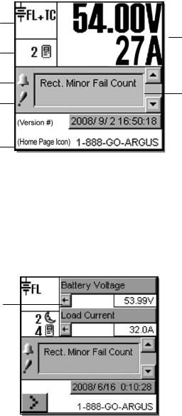
4.2Normal Operation
This is the default-operating mode or “home page.” The GUI displays system status information and monitors all input channels.
Active areas to tap and activate are noted below:
Mode Status
Analog Signals Display
Rectifiers Information Converter Report may also be accessed via this active area
Alarm condition icon
Alarm Indication
Priority icon
Software Version |
|
|
|
Date and Time |
|
||||
|
|
Home Page Icon, tap to login
Figure 2–Sample of CXC default operating screen
4.2.1Activation/Tapping
Each active area is touch sensitive and responds better to a stylus suited for this purpose; i.e. PDA type.
The Analog Signals Display on the home page will show two lines of text for system voltage and current by default (Figure 2). Tap this active area to decrease the font size for four lines of text showing the system values and the corresponding labels (Figure 3). The large font reappears after 20 minutes of inactivity (no user input); otherwise tap again to enter a new window of operation (Figure 10) or select a different active area as required. Refer also to 5.1.3.
The arrows beside the system values enable the user to return to the larger font of the normal (default) home page
The display also returns to the default page when the user logs out from the menu.
A new window of operation will open for the active area selected, whereupon:
Buttons may be tapped to evoke commands.
Lists or pull-down menus enable item selection.
Sliders and scroll bars may be used for navigation.
Pop-up windows may appear from selected items; to be cleared as the user follows the prompts.
Figure 3–Sample of CXC home page with user-activated Analog Signals Display
Alpha Technologies Ltd. |
034-136-C0 Rev B WC |
Printed in Canada. © 2010 Alpha Technologies Ltd. ALPHA and CORDEX are trademarks of Alpha Technologies Ltd. All Rights Reserved. |
Page 15 of 122 |

Refer to the back of this manual for Factory Service and Technical Support contact information
4.2.2LCD Touch Screen Calibration
A touch screen calibration page may be evoked from the user interface default operating screen: Perform a diagonal action or "swipe" from the top right area of the LCD to the bottom left area:
CAUTION: Do not use a pen, pencil or other sharp object to tap on the CXC screen. This will scratch the screen and may void the warranty.
Figure 4–Begin LCD touch screen calibration (default operating screen)
When the calibration screen appears, tap on the center of the first target within 20 seconds to complete this step:
Tap on the center of the first target (top left area of the screen)
Calibration will be ignored if the user does |
|
Count down timer; calibration will be |
|
ignored when time runs out |
|
not tap in the general area of the target |
|
|
|
|
|
(correct area is the size of the target icon) |
|
|
Figure 5– LCD touch screen calibration screen target one
Tap on the center of the second target (bottom right area of the screen) to complete the calibration:
If the user does not tap in the general area of the first target, then calibration will not be saved no matter what happens in the second target
Count down timer; calibration will be ignored when time runs out
Tap on the center of the second target and calibration will be saved automatically
Figure 6– LCD touch screen calibration screen target two
NOTE: Both the targets must be tapped correctly for the calibration to take effect. This is done to prevent the calibration from changing dramatically from the default.
Alpha Technologies Ltd. |
034-136-C0 Rev B WC |
Printed in Canada. © 2010 Alpha Technologies Ltd. ALPHA and CORDEX are trademarks of Alpha Technologies Ltd. All Rights Reserved. |
Page 16 of 122 |

Visit the Alpha website at www.alpha.ca for the latest manual and product downloads
4.3Mode Status (active area) and Temp Comp Indication
The CXC has four modes of operation: float (FL), equalize (EQ), boost (BST) and battery test (BT). The mode, along with temperature compensation (TC or Temp Comp) activation, is indicated in the top left “active area” of the GUI, see Figure 2. The time duration, until the mode changes, will also be shown in that active area.
Tap this active area to enter a new screen, or window of operation, for mode selection, see Figure 7 below:
Mode (+Temp Comp) display
Mode Selection buttons
Additional functions display here; such as, countdowns and status of battery runtime
FL + TC |
|
|
|
|
Battery Voltage and |
54.00V |
250A |
|
|
Load Current display |
|
|
|||||
|
|
|
Alarm Indication
Battery Voltage Mode
FL EQ BT BST
Periodic Auto-EQ Disabled
Auto BT Disabled
Verify action and
return to previous screen
Figure 7–Mode selection screen
4.3.1Float (FL) Mode
This is the CXC’s default mode at start up and during normal system operation. When in this mode, the rectifier’s charge (or output) voltage is driven by the float voltage setting found in the CXC’s Rectifiers menu, see 6.3.2. The icon (message) FL will display on the GUI’s upper left corner (Figure 2) when the CXC is operating in float mode.
Do not adjust the float voltage of the rectifiers when they are in Current Limit.
When operating in a mode other than float mode, tap the FL mode selection button to return to the defaultoperating mode. Tap the “check mark” button in the lower right corner of the GUI to verify the action and return to the previous screen.
4.3.2Equalize (EQ) Mode
The equalize mode is used to equalize charge a battery string. This mode can be selected via the Mode Status active area and by tapping the EQ mode selection button or by sending an external command; e.g., via web interface. When in this mode, the rectifier’s charge (or output) voltage is driven by the equalize voltage setting found in the CXC’s Rectifiers menu, see 6.3.2. The EQ icon will display when the CXC is operating in equalize mode.
A maximum time limit for equalize charging can be programmed to prevent accidental over-charge of a battery string. This limit is determined by the setting found in the EQ Timeout menu, see 6.3.2.10. Do not adjust the equalize level of the rectifiers while they are in current limit.
When operating in EQ mode, the text below the Mode Selection buttons (shown above) will display the time until FL mode in hours. Tap the “check mark” button in the lower right corner of the GUI to verify the action and return to the previous screen.
4.3.3Boost (BST) Mode
This feature (see 0) provides the supervisor with the means to equalize charge the battery at a higher voltage relative to the connected load. Activation is manual and certain conditions must be met to prevent damage to the load.
A custom alarm must be created to include all the desired factors that must be taken into account before activating BST mode. This mode will then only be permitted if the alarm is false.
Once activated, BST mode concludes with a timeout or whenever the status of the custom alarm is true and reverts to FL mode. BST mode can also be cancelled if the conditions that are required in order to activate BST mode have changed.
Alpha Technologies Ltd. |
034-136-C0 Rev B WC |
Printed in Canada. © 2010 Alpha Technologies Ltd. ALPHA and CORDEX are trademarks of Alpha Technologies Ltd. All Rights Reserved. |
Page 17 of 122 |
Refer to the back of this manual for Factory Service and Technical Support contact information
4.3.4Battery Discharge Test or Battery Test (BT) Mode
The battery discharge test is used to update the status of the lead acid battery capacity. BT can be set to run automatically or can be initiated manually (via Mode Selection button).
4.3.4.1Definitions
End/Terminal Voltage — The voltage at which the test will end or terminate.
Timeout — The maximum time the test will be permitted to run before it is aborted.
Period in Days — The time between each Auto-BT.
Battery On Discharge (BOD) Alarm — This alarm will indicate that the battery is discharging.
4.3.4.2Manual Activation
The user can manually activate the test by tapping the BT mode selection button (Figure 7).
4.3.4.3Auto-BT Feature
This feature will enable the CXC to start a test automatically on a periodic basis. The Supervisor may enable or disable the feature in (BATTERIES) BATTERY TEST\AUTO-BT menu, see 6.4.5.2.
4.3.4.4Tips on Using the BT Mode
Use Charge Current Control (6.4.3) to limit the battery recharge current to the battery manufacturer’s specified maximum value.
The resultant battery capacity estimate will be more accurate if the test is started when the battery is fully charged. If a recent discharge has occurred within the last 96 hours, when a mode change to BT is selected, a dialog box will prompt the user to confirm the mode change.
During a test, the runtime hours will be accessible through the Analog Signals display or Mode Status screen. The runtime hours will reflect the time remaining in the test.
The runtime will be displayed after the start of an outage and when a BOD condition is detected; i.e., battery is sourcing current and voltage is below open circuit.
When a test is started by the remote BT feature, the battery log will show “Remote BT” in the Event Type column.
The BT depth of discharge (DOD) can be accessed via the Analog Signals Display; provides an additional indication of test progress.
BT information is available via the CXC’s battery log web page when a test is in progress. In addition, the new battery capacity estimate can be accessed via the Analog Signals display at any time before, during or after the test.
Alpha Technologies Ltd. |
034-136-C0 Rev B WC |
Printed in Canada. © 2010 Alpha Technologies Ltd. ALPHA and CORDEX are trademarks of Alpha Technologies Ltd. All Rights Reserved. |
Page 18 of 122 |
Visit the Alpha website at www.alpha.ca for the latest manual and product downloads
4.3.4.5BT Initiation
When the test begins, an entry will be made in the event log. If enabled, an alarm will provide a warning to indicate that a Battery Test is in progress.
The test will continue, depending on the type of rectifier in use, in accordance with the following algorithms (as applied to lead acid batteries):
Algorithm 1 — For rectifiers that support Battery Test (BT) mode:
1.A command is sent to put the rectifiers into BT mode.
2.BT mode runs for the period set as Timeout or until BT End Voltage is reached.
Algorithm 2 — For (Pathfinder) rectifiers that do not support BT mode:
1.Rectifiers are commanded to go to nominal voltage.
2.The rectifiers are periodically scanned to be sure that they do not begin sourcing current. When 3% DOD is reached and the rectifiers are still not sourcing current, the rectifiers are turned off.
3.The rectifier float setting is reset to the setting stored in the system controller.
4.When the system voltage reaches the end (termination) voltage or a timeout occurs, the system controller will command the rectifiers to turn ON and enter FL mode.
4.3.4.6Activity During BT Mode
Temp Comp and Power Save features are suspended during a battery test. When the battery is discharging, a BOD alarm will be active.
During a test, the mode symbol in the upper left corner of the GUI will be similar to the FL mode symbol except that the letters “FL” will be replaced with “BT.”
Runtime estimate begins at 3% DOD.
Capacity estimate also begins at 3% DOD, but will not be stored unless DOD > 20%; the point at which reasonable accuracy can be assured.
4.3.4.7AC Failure During BT Mode
If the AC fails during a battery test, the test will be aborted. This will place the rectifiers into a state that will enable them to resume providing power to the load when AC returns. If the Runtime is being displayed, it will continue to update.
4.3.4.8Addition of Rectifiers During BT Mode
If rectifiers are added to the system when a battery test is active, they will be placed into the same state as the other rectifiers. They will be:
Placed into BT mode (for rectifiers that support BT mode), or
Placed into remote shutdown, or
Set to the same voltage as the other rectifiers.
4.3.4.9Conditions to Watch for During BT Mode
If the voltage drops below 47V before or when 3% DOD is reached, the test is aborted and the battery capacity is set to 0% (resulting in a Battery Capacity Low alarm). This provides an indication that the battery is very weak2. The battery capacity must be manually reset to 100%, or to the percentage of expected battery capacity before the next battery test is started, in order for the battery monitor to again attempt to compute the battery capacity.
If rectifiers are seen to be sourcing current during the test and the battery ceases to be discharging, the test is aborted.
4.3.4.10Canceling BT Mode
BT mode can be cancelled by changing mode to FL or EQ.
2 In some cases, incorrect battery parameters can cause this condition to occur with a good battery.
Alpha Technologies Ltd. |
034-136-C0 Rev B WC |
Printed in Canada. © 2010 Alpha Technologies Ltd. ALPHA and CORDEX are trademarks of Alpha Technologies Ltd. All Rights Reserved. |
Page 19 of 122 |
Refer to the back of this manual for Factory Service and Technical Support contact information
4.3.4.11Battery Discharge Test Completion
The test is considered complete once the battery begins to charge. This could be due to the test ending from timeout, the system reaching the end (termination) voltage or an abort condition.
Once the battery begins to charge, the recharge cycle begins. Live battery recharge information is available from the battery log web page.
4.3.4.12Remote BT Mode
This feature will force a transition to BT mode when a user-defined condition (custom alarm) is true.
When this condition is true, BT mode is entered regardless of the regular safety checks that are performed during manual or automatic changes to BT mode. BT mode stays active as long as the condition remains true.
A check box is used to enable/disable this feature. The default is disabled. If the condition is true and the check box is disabled, then the system will be put into FL mode.
If the condition becomes false, disabled, invalid, or the (assigned custom alarm) equation is empty, the system will be put into FL mode.
NOTE: This feature is exclusive for the Cordex series of rectifiers. If Remote BT is active and a rectifier other than the Cordex series is added to the system then Remote BT will be aborted.
Alpha Technologies Ltd. |
034-136-C0 Rev B WC |
Printed in Canada. © 2010 Alpha Technologies Ltd. ALPHA and CORDEX are trademarks of Alpha Technologies Ltd. All Rights Reserved. |
Page 20 of 122 |
Visit the Alpha website at www.alpha.ca for the latest manual and product downloads
4.4Rectifiers (and Converters) Information (active area)
Tap this active area, located below Mode Status on the “home” page (Figure 2), to enter a new window of operation for converter/rectifier updates and reports, see Figure 8 below:
Mode (+Temp Comp) display |
|
FL + TC |
|
|
|
|
Battery Volts and |
|
54.00V |
250A |
|
|
|||
|
|
|
Load Current display |
||||
|
|
||||||
|
|
|
|
|
|
|
Alarm Indication
Inventory Update
Select operation here
Rectifier Report
Converter Report
Return to previous screen
Figure 8–Update (inventory) and report selection screen
4.4.1Inventory Update
This button will enable the user to re-acquire all the attached modules to the CXC; to verify the existence of all connected modules. Tap to evoke this command (and return to the home page).
A pop-up window (not shown here) will appear over the home page to show a progress bar of the number of modules acquired during the update that has just been evoked. Tap the “X” button to clear the pop-up from the active area.
Inventory update must be done whenever a module is removed from the system. The system is polled with respect to the following scenarios:
Module has failed and is no longer able to communicate, or
User has removed a module from the system.
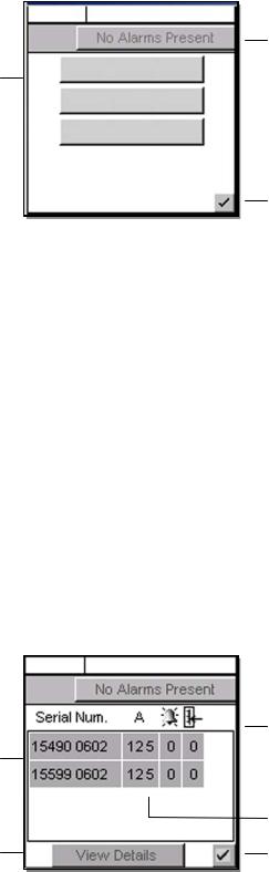
4.4.2Rectifier Report (Converter Report similar)
This button (or menu item in 6.3.1) will enable the user to view, in a list (report), all of the acquired modules in the system. Tap to evoke this command.
A new active area will be displayed, see Figure 9 below. The first column lists the serial numbers of the modules. The report then displays the current output (A) of each module (or toggle for % of maximum output) and the number of active alarms (if that module is issuing an alarm). The rightmost column displays the number of settings out of tolerance (OOT per web interface).
FL + TC |
54.00V |
250A |
Select module to view details
Tap View Details to produce a new window with pull-down menus showing all of the alarms and settings that are out of tolerance
Report headings for serial number, current display (% or A), number of alarms and settings out of tolerance (OOT)
A value of ‘---‘ indicates Comms Lost
Return to previous screen
Figure 9–Rectifier (or Converter) report screen
Rectifier (or Converter) Locate Feature — Once a module is selected, the (module) LED’s will start flashing.
Alpha Technologies Ltd. |
034-136-C0 Rev B WC |
Printed in Canada. © 2010 Alpha Technologies Ltd. ALPHA and CORDEX are trademarks of Alpha Technologies Ltd. All Rights Reserved. |
Page 21 of 122 |

Refer to the back of this manual for Factory Service and Technical Support contact information
4.5Analog Signals Display (active area)
Tap this active area3, top right of the “home” page (Figure 2), to enter a new window of operation for analog signals display and configuration, see Figure 10 below:
Mode (+Temp Comp) display |
|
FL + TC |
|
|
|
|
|
|
Battery Volts and |
|
|
54.00V |
250A |
|
|
||||
|
|
|
|
|
Load Current display |
||||
|
|
|
|||||||
|
|
|
|
|
|
|
|
|
|
Pull-down menu (heading) also includes: |
|
Controller Signals |
|
|
Alarm Indication |
||||
|
|
|
|||||||
|
|
|
|
||||||
Analog Inputs, Digital Inputs, |
|
|
|
|
|||||
|
|
|
|
||||||
|
|
|
|
|
|
|
|
|
|
Rectifier Signals, Custom Signals, |
|
Load Current |
250 |
|
|
|
|
||
Converter Signals, Counter, |
|
|
|
|
Sliders and scroll bars |
||||
Timers, ADIO Signals |
|
|
|
|
|
|
|
|
|
|
Battery Voltage |
54.00 |
|
|
|
are used for navigation |
|||
Change heading to access |
|
|
|
|
|||||
|
|
|
|
||||||
|
|
|
|
Select menu item to configure |
|||||
menu item desired |
|
Battery Current |
5.4 |
|
|
|
|||
|
|
|
|
|
|||||
Tap to edit selected menu item |
|
|
Configure |
|
|
|
|
Accept changes and |
|
User will be prompted for password |
|
|
|
|
|
|
return to previous screen |
||
|
|
|
|
|
|||||
Figure 10–Analog signals display screen
The item selected from the analog signals active area will now be the highlighted item listed in the new window. The pull-down menu enables the user to select the signal group; signal items are listed below the group heading. Navigate the menu list to select the desired item.
4.5.1Controller Signals
Once a menu item is selected, tap the “Configure” button to produce another window and list of items to navigate, see 6.6.2. To edit items, the User will be prompted for a password (via a pop-up window).
4.5.2Analog Inputs
Once a menu item is selected, tap the “Calibrate” button to produce another window and list of items to navigate, see 6.6.1. To edit items, the User will be prompted for a password (via a pop-up window).
4.5.3Digital Inputs
Under this menu heading, the user can view the list of digital inputs, see Table B.
4.5.4Rectifier Signals
Under this menu heading, the user can view the list of rectifier signals, see Table E.
4.5.5Custom Signals
Once a menu item is selected, tap the “Configure” button to produce another window and list of items to navigate. To edit items, the User will be prompted for a password (via a pop-up window).
4.5.6Converter Signals
Under this menu heading, the user can view the list of converter signals, see Table H.
4.5.7Counter
Once a menu item is selected, tap the “Configure” button to produce another window and list of items to navigate. To edit items, the user will be prompted for a password (via a pop-up window).
4.5.8Timers
Once a menu item is selected, tap the “Configure” button to produce another window and list of items to navigate. To edit items, the user will be prompted for a password (via a pop-up window).
4.5.9ADIO Signals
Under this menu heading, the user can view the live data from an ADIO device (i.e., Cordex Smart Peripherals) connected to the CXC. Refer also to Section 6.6.2.6, Example Four.
3 When labels are not shown, digits are displayed two rows high. See Figure 2 for Normal Operation. Tap to minimize (see Figure 1) and tap again to enter new window of operation.
Alpha Technologies Ltd. |
034-136-C0 Rev B WC |
Printed in Canada. © 2010 Alpha Technologies Ltd. ALPHA and CORDEX are trademarks of Alpha Technologies Ltd. All Rights Reserved. |
Page 22 of 122 |

Visit the Alpha website at www.alpha.ca for the latest manual and product downloads
4.6Alarm Indication (active area)
Within the default operating screen, the Alarm Indication window may show icons on the left margin to indicate various alerts (such as an active alarm and priority of the condition). In the middle of the window, text will scroll indicating alarm notification or status. Navigation keys (on the right) aid the user to view the text.
Tap this active area, located below Analog Signals Display on the “home” page (Figure 2), to enter a new window of operation for alarm display and configuration, see Figure 11 below:
Mode (+Temp Comp) display |
|
FL + TC |
|
|
|
|
|
54.00V |
250A |
||
|
|
||||
|
|
|
|||
|
|
Alarm will scroll here... |
|
||
Tap to silence active alarms |
|
Cutoff All Alarms |
|
||
|
|
||||
|
|
|
Scroll Rate |
|
|
1 s
Tap to view alarm history |
Show Alarm History |
|
Battery Volts and
Load Current display
Discard changes and return to previous screen
Use slider to change alarm scroll rate
Accept changes and return to previous screen
Figure 11–Alarm indication display screen
4.6.1Cutoff All Alarms
Tap “Cutoff All Alarms” (button shown above) to silence active alarms. In addition, on any screen where the alarm indication is shown (as in previous figures), the User may tap the alarm indication “button” to display a pulldown menu (Figure 12 below) for alarm cutoff (also known as ALCO, see 6.5.1):
FL + TC |
54.00V |
250A |
Alarm displays here
Cutoff All Alarms
Cancel
Use pull-down menu to cutoff all alarms
Figure 12–Alarm cutoff pull-down menu
Use pull-down menu to select priority, either major, minor, message, or all
Alarms will display here in a list
Verify action and return to previous screen
Alpha Technologies Ltd. |
034-136-C0 Rev B WC |
Printed in Canada. © 2010 Alpha Technologies Ltd. ALPHA and CORDEX are trademarks of Alpha Technologies Ltd. All Rights Reserved. |
Page 23 of 122 |
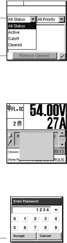
Refer to the back of this manual for Factory Service and Technical Support contact information
4.6.2Alarm History
Tap “Show Alarm History” to enter another screen that will list past alarms. Two pull-down menus enable the user to select which alarms will be displayed according to status and priority, see Figure 13 below:
FL + TC |
54.00V |
250A |
Alarm will scroll here...
Use pull-down menu to select status as shown
Tap to “Remove Cleared” alarms from display
Figure 13–Alarm History screen
4.7Argus Icon (active area)
Tap the Argus icon at the lower left of the “home” page to login (password entry), adjust contrast of display, reset, and select language, see Figure 14 below:
Login
|
|
Contrast |
|
Pop-up window |
|
|
|
||
|
|
Reset |
|
tap to make selection from list of items |
|
|
0: English |
|
|
Argus Icon enables access to menu tree, etc. |
|
1: (Chinese) |
|
|
|
2: Français |
|
|
|
tap to login |
|
|
|
|
|
|
|
|
Figure 14–Argus icon pop-up window on home page
4.7.1Login (password entry)
When the user attempts to login (e.g. tapping the icon and selecting Login from the menu prompt), a pop-up window for password entry will be presented, see Figure 15 below:
Each character of the password entry will |
|
|
Use backspace key |
||
|
|
|
|
|
to erase last entry as needed |
appear in this window for verification |
|
|
|||
|
|
|
|||
|
|
|
|
|
Use number keys to enter password |
|
|
|
|
|
|
Tap to accept or cancel
Figure 15–Password entry pop-up window
NOTE: If the CXC is already being accessed remotely, a pop-up window will appear to notify the local user that she or he will not be able to login and that “Another operator is currently logged in.”
Alpha Technologies Ltd. |
034-136-C0 Rev B WC |
Printed in Canada. © 2010 Alpha Technologies Ltd. ALPHA and CORDEX are trademarks of Alpha Technologies Ltd. All Rights Reserved. |
Page 24 of 122 |

Visit the Alpha website at www.alpha.ca for the latest manual and product downloads
Once the password is verified, appropriate access level will be granted and a pop-up window will provide acknowledgement; e.g., “Supervisor Access Granted.” If no password is entered, the user will be granted User access. In User access mode, the user cannot make changes to parameters but may navigate through menus, see Figure 23.
4.7.2Contrast Adjustment of the GUI
Via the Argus icon, a pop-up window enables the user to access the contrast adjustment of the GUI. Tap “Contrast” on the pop-up window. Figure 16 below shows the contrast adjustment window. Use the slider on the GUI to adjust contrast as desired.
Discard changes and
return to previous screen
Tap slider to increase or decrease contrast of GUI as required
Accept changes and return to previous screen
Figure 16–Contrast adjustment pop-up window
4.7.3Reset
Via the Argus icon, the user can reset the CXC. This enables the CXC to finish saving files to flash memory.
NOTE: The CXCP and CXCR models provide battery backup of time and date; the other CXC models do not.
Tap “Reset” on the pop-up window. A new pop-up window will alert the user “You are about to perform a system reset.”
To abort the operation, tap “Cancel” or the “X” button to clear the pop-up from the active area.
To proceed, tap “Accept” and a pop-up window will notify the user “Performing Reset, please wait…” This window will then be replaced with a window showing a timer counting down from 60 seconds and a button enabling the user to “Reset Now.” A message will also appear in this window to notify the user “It is now safe to reset the system.” The user may then tap the button or wait for the timer to count down and the operation will proceed automatically to completion. The screen will go blank and the LED’s will flash as the CXC performs a short selftest before returning to Normal operating mode.
4.7.4Language Selection
Via the Argus icon, a pop-up window enables the user to select English, French, Portuguese, Spanish or Chinese characters for the display of text labels and messages.
Language files can be uploaded via web interface. The CXC can be set up for a maximum of three language files (default plus two others) at one time pending availability.
Alpha Technologies Ltd. |
034-136-C0 Rev B WC |
Printed in Canada. © 2010 Alpha Technologies Ltd. ALPHA and CORDEX are trademarks of Alpha Technologies Ltd. All Rights Reserved. |
Page 25 of 122 |

Refer to the back of this manual for Factory Service and Technical Support contact information
4.8Date and Time (active area)
On the “home” page (Figure 2), below the Alarm Indication, the date and time are displayed. To change the date (year, month, day) and time (hour, minute, second) settings, tap the active area of the screen to enter a new window of operation, see Figure 17 below:
Tap arrows to increase or decrease values as required
|
|
|
|
|
Discard changes and |
|
Date |
|
|
|
return to previous screen |
2008 |
08 |
|
08 |
|
|
|
Time |
|
|
|
|
09 |
15 |
20 |
|
|
Accept changes and |
|
|
|
|
|
return to previous screen
Figure 17–Date and time setting window
NOTE: The CXCP and CXCR models provide battery backup of time and date; the other CXC models do not.
With the web interface, SNTP (Simple Network Time Protocol) may be used, see 4.10.1. This feature enables synchronization of the CXC device time with an external source; i.e., the user’s network.
4.9Saving Settings
Return to MAIN MENU navigation screen.
1.Press the OPTION button to evoke the SAVE/LOGOUT pop-up window, see 5.1.2.
2.Select SAVE to save the new settings (or select LOGOUT to clear).
A pop-up window will appear for confirmation of the selection.
Alternatively, for the web interface:
1.Click Submit Changes (upper left on web interface window).
2.Click Accept button on the Compare Settings window.
Alpha Technologies Ltd. |
034-136-C0 Rev B WC |
Printed in Canada. © 2010 Alpha Technologies Ltd. ALPHA and CORDEX are trademarks of Alpha Technologies Ltd. All Rights Reserved. |
Page 26 of 122 |

Visit the Alpha website at www.alpha.ca for the latest manual and product downloads
4.10Overview of Web Interface
Refer to Chapter 9 to establish remote communications, then launch Internet Explorer 6 or greater.
Under Tools\Internet Options\Security, add the logon address of the CXC to the “Trusted Sites.”
Logon to address 10.10.10.201
Figure 18–Enter Network Password window
Enter no USER NAME and default PASSWORD. Select OK to proceed to Language Selection window:
Figure 19–Language Selection window
The following images show examples of windows presented when using a desktop browser to set-up or monitor the CXC – contact Alpha for assistance as required.
Figure 20–Web Interface window (sample home page)
Alpha Technologies Ltd. |
034-136-C0 Rev B WC |
Printed in Canada. © 2010 Alpha Technologies Ltd. ALPHA and CORDEX are trademarks of Alpha Technologies Ltd. All Rights Reserved. |
Page 27 of 122 |
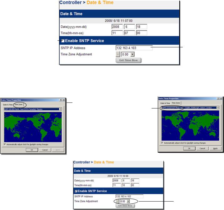
Refer to the back of this manual for Factory Service and Technical Support contact information
4.10.1SNTP (Simple Network Time Protocol)
This feature enables synchronization of the CXC device time with an external source; i.e., the user’s network. SNTP is an adaptation or basic subset of NTP which is used for more comprehensive device time synchronization (see www.NTP.org).
CAUTION
The CXC SNTP client will only accept responses from the external server with the ‘stratum’ parameter set in the range of 1 through 14.
With the web interface, select the Controller page and then the Date & Time window:
Toggle the check box to
Enable SNTP Service
Enter target network address for SNTP source
Figure 21–Date & Time window (Controller page)
To verify the Date/Time properties of the PC, select Start, Settings then Control Panel (Windows® 2000 operating system). Select Date/Time and verify properties with the target network:
Select the tab for Time Zone
Use the pull-down menu to select the correct time zone; e.g. Pacific Time
In this example, the Time Zone
Adjustment for the CXC is –8:00
Use the “-“ button in addition to the pull-down menu to change the Time Zone Adjustment,
then select Get Time Now to
synchronize
Figure 22–Example of time zone adjustment
Select Get Time Now to synchronize.
NOTE: SNTP service will automatically re-synchronize twenty-four hours from the time of the last synchronization.
Alpha Technologies Ltd. |
034-136-C0 Rev B WC |
Printed in Canada. © 2010 Alpha Technologies Ltd. ALPHA and CORDEX are trademarks of Alpha Technologies Ltd. All Rights Reserved. |
Page 28 of 122 |
 Loading...