

Page 1

3000 AND 4000 ELECTRONIC CONTROLS TROUBLESHOOTING MANUAL
PREFACE
Welcome to the TS2973EN Troubleshooting Manual. We make every effort to keep our service
information current and accurate. Because of the time lag involved with writing and printing processes,
the transmission TCM may report a code that has not yet been added to this document. If you encounter
a code that is not yet in this publication, please call the Allison Transmission Technical Assistance Center
at 1-800-252-5283.
Go to the Table of Contents.
Copyright© 2005 General Motors Corp.
Page 2

2005 OCTOBER
Troubleshooting
REV. 1 OCTOBER 2006
Manual
TS2973EN
Allison Transmission
VOCATIONAL MODELS
3000 VOCATIONAL MODELS
3000 HS 3500 RDS B 300(P)(R)
3000 RDS 3500 EVS B 400(P)(R)
3000 EVS T 200
3000 MH T 300
3000 PTS
3000 TRV
3200 SP 3500 SP 3700 SP
3200 TRV
MD 3060 MD 3560 MD 3070PT
MD 3066
4000 VOCATIONAL MODELS
4000 EVS 4500 EVS 4700 EVS 4800 EVS B 500
4000 HS 4500 HS 4700 RDS
4000 MH 4500 RDS
4000 RDS 4500 SP
4000 TRV 4500 TRV
HD 4060 HD 4560 HD 4070 HD 4076 B 500P
HD 4060P HD 4560P HD 4070P B 500R
HD 4060R HD 4560R HD 4070R B 500PR
HD 4060PR HD 4560PR HD 4070PR T 425
T 450
Allison Transmission, General Motors Corporation
P.O. Box 894 Indianapolis, Indiana 46206-0894
www.allisontransmission.com
Printed in USA
Copyright © 2005 General Motors Corporation
Page 3

WTEC III ELECTRONIC CONTROLS TROUBLESHOOTING MANUAL
FOREWORD—How to Use This Manual
This manual provides troubleshooting information for the 3000 and 4000 Product Families Transmissions. Service
Manuals SM2148EN and SM2457EN, plus Parts Catalogs PC2150EN and PC2456EN may be used in conjunction
with this manual.
This manual includes:
•
Description of the WTEC III electronic control system.
•
Description of the electronic control system components.
•
Description of diagnostic codes, system responses to faults, and troubleshooting.
•
Wire, terminal, and connector repair information.
Specific instructions for using many of the available or required service tools and equipment are not included in
this manual. The service tool manufacturer will furnish instructions for using the tools or equipment.
Additional information may be published from time to time in Service Information Letters (SIL) and will be
included in future revisions of this and other manuals. Please use these SILs to obtain up-to-date information
concerning Allison Transmission products.
This publication is revised periodically to include improvements, new models, special tools, and procedures. A
revision is indicated by a new date on the title page and in the lower left corner of the rear cover. Contact your
Allison Transmission service outlet for the currently applicable publication. Additional copies of this publication
may be purchased from authorized Allison Transmission service outlets. Look in your telephone directory under
the heading of Transmissions—Truck, Tractor, etc.
Take time to review the Table of Contents and the manual. Reviewing the Table of Contents will aid you in quickly
locating information.
NOTE: Allison Transmission is providing for service of wiring harnesses and wiring harness components as
follows:
•
Repair parts for the internal wiring harness and for wiring harness components attached to the shift selector
will be available through the Allison Transmission Parts Distribution Center (PDC). Use the P/N from your
appropriate parts catalog or from Appendix E in this manual. Allison Transmission (AT) is responsible for
warranty on these parts.
•
Repair parts for the external harnesses and external harness components must be obtained from St. Clair
Technologies Inc. (SCTI). SCTI provides parts to any Allison customer or OEM and is responsible for
warranty on these parts. SCTI recognizes AT, manufacturers, and SCTI part numbers. SCTI provides a
technical HELPLINE at 519-627-1673 (Wallaceburg). SCTI will have parts catalogs available. The SCTI
addresses and phone numbers for parts outlets are:
St. Clair Technologies, Inc.
920 Old Glass Road
Wallaceburg, Ontario, N8A 4L8
Phone: 519-627-1673
Fax: 519-627-4227
St. Clair Technologies, Inc.
Calle Damanti S/N Col
Guadalupe—Guaymas
Sonora, Mexico CP85440
Phone: 011-526-2222-43834
Fax: 011-526 2222-43553
•
St. Clair Technologies, Inc. stocks a WTEC III external harness repair kit, P/N 29532362, as a source for
some external harness repair parts. SCTI is the source for external harness repair parts.
ii Copyright © 2005 General Motors Corp.
Page 4

WTEC III ELECTRONIC CONTROLS TROUBLESHOOTING MANUAL
IMPORTANT SAFETY NOTICE
IT IS YOUR RESPONSIBILITY to be completely familiar with the warnings and cautions
used in this manual. These warnings and cautions advise against using specific service
procedures that can result in personal injury, equipment damage, or cause the equipment to
become unsafe. These warnings and cautions are not exhaustive. Allison Transmission could
not possibly know, evaluate, or advise the service trade of all conceivable procedures by which
service might be performed or of the possible hazardous consequences of each procedure.
Consequently, Allison Transmission has not undertaken any such broad evaluation.
Accordingly, ANYONE WHO USES A SERVICE PROCEDURE OR TOOL WHICH IS NOT
RECOMMENDED BY ALLISON TRANSMISSION MUST first be thoroughly satisfied
that neither personal safety nor equipment safety will be jeopardized by the service
procedures used.
Also, be sure to review and observe WARNINGS, CAUTIONS, and NOTES provided by the
vehicle manufacturer and/or body builder before servicing the Allison transmission in that
vehicle.
Proper service and repair is important to the safe and reliable operation of the equipment.
The service procedures recommended by Allison Transmission and described in this manual
are effective methods for performing troubleshooting operations. Some procedures require
using specially designed tools. Use special tools when and in the manner recommended.
The WARNINGS, CAUTIONS, and NOTES in this manual apply only to the Allison
transmission and not to other vehicle systems which may interact with the transmission. Be
sure to review and observe any vehicle system information provided by the vehicle
manufacturer and/or body builder at all times the Allison transmission is being serviced.
WARNINGS, CAUTIONS, AND NOTES
Three types of headings are used in this manual to attract your attention:
WARNING!
Is used when an operating procedure, practice, etc., which, if not correctly followed,
could result in injury or loss of life.
CAUTION:
NOTE: Is used when an operating procedure, practice, etc., is essential to highlight.
Is used when an operating procedure, practice, etc., which, if not strictly observed, could
result in damage to or destruction of equipment.
Copyright © 2005 General Motors Corp. iii
Page 5

,
WTEC III ELECTRONIC CONTROLS TROUBLESHOOTING MANUAL
TRADEMARKS USED IN THIS MANUAL
The following trademarks are the property of the companies indicated:
•
Allison DOC
•
DEXRON
®
•
LPS
Cleaner is a registered trademark of LPS Laboratories.
•
Loctite
•
MagiKey
•
•
®
Teflon
TranSynd
TM
is a trademark of General Motors Corporation.
®
is a registered trademark of General Motors Corporation.
®
is a registered trademark of the Loctite Corporation.
®
is a registered trademark of NEXIQ Technologies, Inc.
is a registered trademark of the DuPont Corporation.
TM
is a trademark of Castrol Ltd.
SHIFT SELECTOR TERMS AND DISPLAY INDICATIONS
Shift selector terms and displays are represented in this manual as follows:
Button Names —
•
•
Transmission Ranges— D (Drive), N (Neutral), R (Reverse), 1 (First), 2 (Second), etc.
•
Displays—“ o , L ”; “ o , K ”, etc. (Display occurs one character at a time.)
, “display mode”, MODE , etc.
↑
↓
iv Copyright © 2005 General Motors Corp.
Page 6

WTEC III ELECTRONIC CONTROLS TROUBLESHOOTING MANUAL
3000 AND 4000 ELECTRONIC CONTROLS TROUBLESHOOTING MANUAL
TABLE OF CONTENTS
Foreword. . . . . . . . . . . . . . . . . . . . . . . . . . . . . . . . . . . . . . . . . . . . . . . . . . . . . . . . . . . . . . . . . . . . . . . . . . . . . ii
SAFETY INFORMATION
Important Safety Notice . . . . . . . . . . . . . . . . . . . . . . . . . . . . . . . . . . . . . . . . . . . . . . . . . . . . . . . . . . . .iii
Warnings, Cautions, and Notes. . . . . . . . . . . . . . . . . . . . . . . . . . . . . . . . . . . . . . . . . . . . . . . . . . . . . . .iii
TRADEMARKS USED IN THIS MANUAL . . . . . . . . . . . . . . . . . . . . . . . . . . . . . . . . . . . . . . . . . . . . . .iv
SHIFT SELECYOR TERMS AND DISPLAY INDICATIONS . . . . . . . . . . . . . . . . . . . . . . . . . . . . . .iv
SECTION 1. GENERAL DESCRIPTION
1–1. TRANSMISSION. . . . . . . . . . . . . . . . . . . . . . . . . . . . . . . . . . . . . . . . . . . . . . . . . . . . . . . . . . . . . . . 1–1
1–2. ELECTRONIC CONTROL UNIT (ECU) . . . . . . . . . . . . . . . . . . . . . . . . . . . . . . . . . . . . . . . . . . . . 1–3
1–3. SHIFT SELECTOR . . . . . . . . . . . . . . . . . . . . . . . . . . . . . . . . . . . . . . . . . . . . . . . . . . . . . . . . . . . . . 1–3
A. Pushbutton Shift Selector . . . . . . . . . . . . . . . . . . . . . . . . . . . . . . . . . . . . . . . . . . . . . . . . . . . . . . 1–3
B. Lever Shift Selector . . . . . . . . . . . . . . . . . . . . . . . . . . . . . . . . . . . . . . . . . . . . . . . . . . . . . . . . . . . 1–4
1–4. THROTTLE POSITION SENSOR. . . . . . . . . . . . . . . . . . . . . . . . . . . . . . . . . . . . . . . . . . . . . . . . . . 1–5
1–5. SPEED SENSORS . . . . . . . . . . . . . . . . . . . . . . . . . . . . . . . . . . . . . . . . . . . . . . . . . . . . . . . . . . . . . . 1–5
1–6. CONTROL MODULE . . . . . . . . . . . . . . . . . . . . . . . . . . . . . . . . . . . . . . . . . . . . . . . . . . . . . . . . . . . 1–6
1–7. WIRING HARNESSES . . . . . . . . . . . . . . . . . . . . . . . . . . . . . . . . . . . . . . . . . . . . . . . . . . . . . . . . . . 1–8
A. External Wiring Harness . . . . . . . . . . . . . . . . . . . . . . . . . . . . . . . . . . . . . . . . . . . . . . . . . . . . . . . 1–8
B. Internal Wiring Harness. . . . . . . . . . . . . . . . . . . . . . . . . . . . . . . . . . . . . . . . . . . . . . . . . . . . . . . 1–10
1–8. VEHICLE INTERFACE MODULE. . . . . . . . . . . . . . . . . . . . . . . . . . . . . . . . . . . . . . . . . . . . . . . . 1–10
1–9. AUTODETECT FEATURE (V8, V8A, V9A SOFTWARE) . . . . . . . . . . . . . . . . . . . . . . . . . . . . . 1–11
A. Retarder . . . . . . . . . . . . . . . . . . . . . . . . . . . . . . . . . . . . . . . . . . . . . . . . . . . . . . . . . . . . . . . . . . 1–11
B. Oil Level Sensor . . . . . . . . . . . . . . . . . . . . . . . . . . . . . . . . . . . . . . . . . . . . . . . . . . . . . . . . . . . . 1–11
C. Throttle Source (V8, V8A Software—See Paragraph 1–10C For V9A). . . . . . . . . . . . . . . . . . 1–12
D. Engine Coolant Temperature Sensor Source . . . . . . . . . . . . . . . . . . . . . . . . . . . . . . . . . . . . . . . 1–12
1–10. AUTODETECT FEATURE (V9A, V9B, AND V9C SOFTWARE) . . . . . . . . . . . . . . . . . . . . . . . 1–12
A. Retarder . . . . . . . . . . . . . . . . . . . . . . . . . . . . . . . . . . . . . . . . . . . . . . . . . . . . . . . . . . . . . . . . . . 1–12
B. Oil Level Sensor (OLS) . . . . . . . . . . . . . . . . . . . . . . . . . . . . . . . . . . . . . . . . . . . . . . . . . . . . . . . 1–12
C. Throttle Source (Also Applies to V9 Software). . . . . . . . . . . . . . . . . . . . . . . . . . . . . . . . . . . . . 1–13
D. Engine Coolant Temperature . . . . . . . . . . . . . . . . . . . . . . . . . . . . . . . . . . . . . . . . . . . . . . . . . . 1–13
1–11. TRANSID FEATURE . . . . . . . . . . . . . . . . . . . . . . . . . . . . . . . . . . . . . . . . . . . . . . . . . . . . . . . . . . 1–13
A. General Description . . . . . . . . . . . . . . . . . . . . . . . . . . . . . . . . . . . . . . . . . . . . . . . . . . . . . . . . . 1–13
B. Transmission Changes Versus TransID Number . . . . . . . . . . . . . . . . . . . . . . . . . . . . . . . . . . . 1–14
C. Compatibility Between TransID Level And ECU Calibration Level . . . . . . . . . . . . . . . . . . . . 1–16
Page
Copyright © 2005 General Motors Corp. v
Page 7

WTEC III ELECTRONIC CONTROLS TROUBLESHOOTING MANUAL
3000 AND 4000 ELECTRONIC CONTROLS TROUBLESHOOTING MANUAL
TABLE OF CONTENTS(Cont'd)
SECTION 2. DEFINITIONS AND ABBREVIATIONS
2–1. CHECK TRANS LIGHT . . . . . . . . . . . . . . . . . . . . . . . . . . . . . . . . . . . . . . . . . . . . . . . . . . . . . . . . . 2–1
2–2. ALLISON TRANSMISSION DIAGNOSTIC TOOL . . . . . . . . . . . . . . . . . . . . . . . . . . . . . . . . . . . 2–1
Basic Features . . . . . . . . . . . . . . . . . . . . . . . . . . . . . . . . . . . . . . . . . . . . . . . . . . . . . . . . . . . . . . . . . . 2–1
PC Platform. . . . . . . . . . . . . . . . . . . . . . . . . . . . . . . . . . . . . . . . . . . . . . . . . . . . . . . . . . . . . . . . . . . . 2–2
2–3. ABBREVIATIONS. . . . . . . . . . . . . . . . . . . . . . . . . . . . . . . . . . . . . . . . . . . . . . . . . . . . . . . . . . . . . . 2–3
SECTION 3. BASIC KNOWLEDGE
3–1. BASIC KNOWLEDGE REQUIRED . . . . . . . . . . . . . . . . . . . . . . . . . . . . . . . . . . . . . . . . . . . . . . . . 3–1
3–2. USING THE TROUBLESHOOTING MANUAL . . . . . . . . . . . . . . . . . . . . . . . . . . . . . . . . . . . . . . 3–2
3–3. SYSTEM OVERVIEW. . . . . . . . . . . . . . . . . . . . . . . . . . . . . . . . . . . . . . . . . . . . . . . . . . . . . . . . . . . 3–2
3–4. IMPORTANT INFORMATION IN THE TROUBLESHOOTING PROCESS . . . . . . . . . . . . . . . . 3–2
3–5. BEGINNING THE TROUBLESHOOTING PROCESS . . . . . . . . . . . . . . . . . . . . . . . . . . . . . . . . . 3–3
Page
SECTION 4. WIRE TESTING PROCEDURES
4–1. TESTING FOR OPENS, SHORTS BETWEEN WIRES, AND SHORTS-TO-GROUND . . . . . . . 4–1
4–2. TESTING AT TRANSMISSION CONNECTOR AND THE INTERNAL HARNESS
FOR OPENS, SHORTS BETWEEN WIRES, AND SHORTS-TO-GROUND . . . . . . . . . . . . . . . . 4–3
SECTION 5. OIL LEVEL SENSOR
5–1. INTRODUCTION. . . . . . . . . . . . . . . . . . . . . . . . . . . . . . . . . . . . . . . . . . . . . . . . . . . . . . . . . . . . . . . 5–1
5–2. ELECTRONIC FLUID LEVEL CHECK (SHIFT SELECTOR). . . . . . . . . . . . . . . . . . . . . . . . . . . 5–3
A. Fluid Level Check Procedure . . . . . . . . . . . . . . . . . . . . . . . . . . . . . . . . . . . . . . . . . . . . . . . . . . . 5–3
5–3. ELECTRONIC FLUID LEVEL CHECK (ALLISON DOC™ FOR PC–SERVICE TOOL) . . . . . 5–5
A. Fluid Level Check Procedure . . . . . . . . . . . . . . . . . . . . . . . . . . . . . . . . . . . . . . . . . . . . . . . . . . . 5–5
SECTION 6. DIAGNOSTIC CODES
6–1. DIAGNOSTIC CODE MEMORY . . . . . . . . . . . . . . . . . . . . . . . . . . . . . . . . . . . . . . . . . . . . . . . . . . 6–1
6–2. CODE READING AND CODE CLEARING . . . . . . . . . . . . . . . . . . . . . . . . . . . . . . . . . . . . . . . . . 6–1
6–3. DIAGNOSTIC CODE RESPONSE . . . . . . . . . . . . . . . . . . . . . . . . . . . . . . . . . . . . . . . . . . . . . . . . . 6–3
6–4. SHIFT SELECTOR DISPLAYS RELATED TO ACTIVE CODES . . . . . . . . . . . . . . . . . . . . . . . . 6–4
6–5. DIAGNOSTIC CODE LIST AND DESCRIPTION. . . . . . . . . . . . . . . . . . . . . . . . . . . . . . . . . . . . . 6–4
6–6. DIAGNOSTIC CODE TROUBLESHOOTING. . . . . . . . . . . . . . . . . . . . . . . . . . . . . . . . . . . . . . . 6–16
A. Beginning the Troubleshooting Process . . . . . . . . . . . . . . . . . . . . . . . . . . . . . . . . . . . . . . . . . . 6–16
B. Solenoid Locations . . . . . . . . . . . . . . . . . . . . . . . . . . . . . . . . . . . . . . . . . . . . . . . . . . . . . . . . . . 6–16
C. Diagnostic Code Schematics . . . . . . . . . . . . . . . . . . . . . . . . . . . . . . . . . . . . . . . . . . . . . . . . . . . 6–16
D. Wire/Terminal Numbering Scheme . . . . . . . . . . . . . . . . . . . . . . . . . . . . . . . . . . . . . . . . . . . . . . 6–17
vi Copyright © 2005 General Motors Corp.
Page 8

WTEC III ELECTRONIC CONTROLS TROUBLESHOOTING MANUAL
3000 AND 4000 ELECTRONIC CONTROLS TROUBLESHOOTING MANUAL
TABLE OF CONTENTS(Cont'd)
SECTION 7. INPUT AND OUTPUT FUNCTIONS
7–1. INPUT FUNCTIONS . . . . . . . . . . . . . . . . . . . . . . . . . . . . . . . . . . . . . . . . . . . . . . . . . . . . . . . . . . . 7–1
7–2. OUTPUT FUNCTIONS . . . . . . . . . . . . . . . . . . . . . . . . . . . . . . . . . . . . . . . . . . . . . . . . . . . . . . . . . . 7–3
SECTION 8. GENERAL TROUBLESHOOTING OF PERFORMANCE COMPLAINTS
APPENDICES
A. IDENTIFICATION OF POTENTIAL CIRCUIT PROBLEMS. . . . . . . . . . . . . . . . . . . . . . . . . . . .A–1
B. MEASURING CLUTCH AND RETARDER PRESSURES . . . . . . . . . . . . . . . . . . . . . . . . . . . . . . B–1
C. SOLENOID AND CLUTCH CHART . . . . . . . . . . . . . . . . . . . . . . . . . . . . . . . . . . . . . . . . . . . . . . . C–1
D. WIRE/CONNECTOR CHART. . . . . . . . . . . . . . . . . . . . . . . . . . . . . . . . . . . . . . . . . . . . . . . . . . . . .D–1
E. CONNECTOR PART NUMBERS, TERMINAL PART NUMBERS,
TOOL PART NUMBERS, AND REPAIR INSTRUCTIONS . . . . . . . . . . . . . . . . . . . . . . . . . . . . . E–1
F. THROTTLE POSITION SENSOR ADJUSTMENT . . . . . . . . . . . . . . . . . . . . . . . . . . . . . . . . . . . . F–1
G. WELDING ON VEHICLE/VEHICLE INTERFACE MODULE . . . . . . . . . . . . . . . . . . . . . . . . . .G–1
H. HYDRAULIC SCHEMATICS . . . . . . . . . . . . . . . . . . . . . . . . . . . . . . . . . . . . . . . . . . . . . . . . . . . . .H–1
J. 3000 AND 4000 PRODUCT FAMILIES WIRING SCHEMATIC . . . . . . . . . . . . . . . . . . . . . . . . . J–1
K. TRANSID 1 TEMPERATURE SENSOR AND SOLENOID RESISTANCE CHARTS . . . . . . . .K–1
L. EXTERNALLY-GENERATED ELECTRONIC INTERFERENCE . . . . . . . . . . . . . . . . . . . . . . . . L–1
M. DIAGNOSTIC TREE—HYDRAULIC SYSTEM . . . . . . . . . . . . . . . . . . . . . . . . . . . . . . . . . . . . . M–1
N. DIAGNOSTIC TOOL INFORMATION . . . . . . . . . . . . . . . . . . . . . . . . . . . . . . . . . . . . . . . . . . . . .N–1
P. INPUT/OUTPUT FUNCTIONS . . . . . . . . . . . . . . . . . . . . . . . . . . . . . . . . . . . . . . . . . . . . . . . . . . . P–1
Q. TRANSID 2 AND 3 THERMISTOR TROUBLESHOOTING INFORMATION . . . . . . . . . . . . . .Q–1
R. SAE J1939 COMMUNICATION LINK . . . . . . . . . . . . . . . . . . . . . . . . . . . . . . . . . . . . . . . . . . . . . R–1
Page
Copyright © 2005 General Motors Corp. vii
Page 9

WTEC III ELECTRONIC CONTROLS TROUBLESHOOTING MANUAL
NOTES
viii Copyright © 2005 General Motors Corp.
Page 10
WTEC III ELECTRONIC CONTROLS TROUBLESHOOTING MANUAL
ECTION
S
1—GENERAL DESCRIPTION
1–1. TRANSMISSION
The World Transmission Electronic Controls (WTEC III) system features closed-loop clutch control to provide
superior shift quality over a wide range of operating conditions. The 3000 and 4000 Product Families transmissions
configurations can be programmed to have up to six forward ranges, neutral, and one reverse range. The MD 3070,
3700 SP, HD 4070/4076, 4700 RDS, 4700/4800 EVS, 4700/4800 SP have up to seven forward ranges and one
reverse.
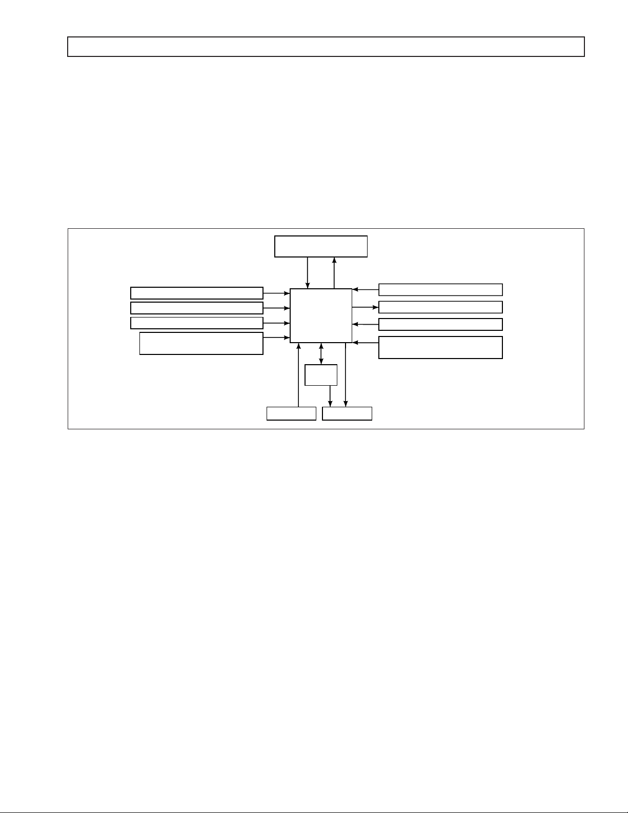
Figure 1–1 is a block diagram of the basic system inputs and outputs.
SHIFT SELECTOR
RANGE AND
MODE SWITCH
SPEED SENSORS
THROTTLE POSITION SENSOR
RETARDER MODULAT ION
VEHICLE/ENGINE
COMMUNICATION LINKS
Figure 1–1. Electronic Control Unit Block Diagram
ECU
VIM
INPUTS OUTPUTS
DISPLAY
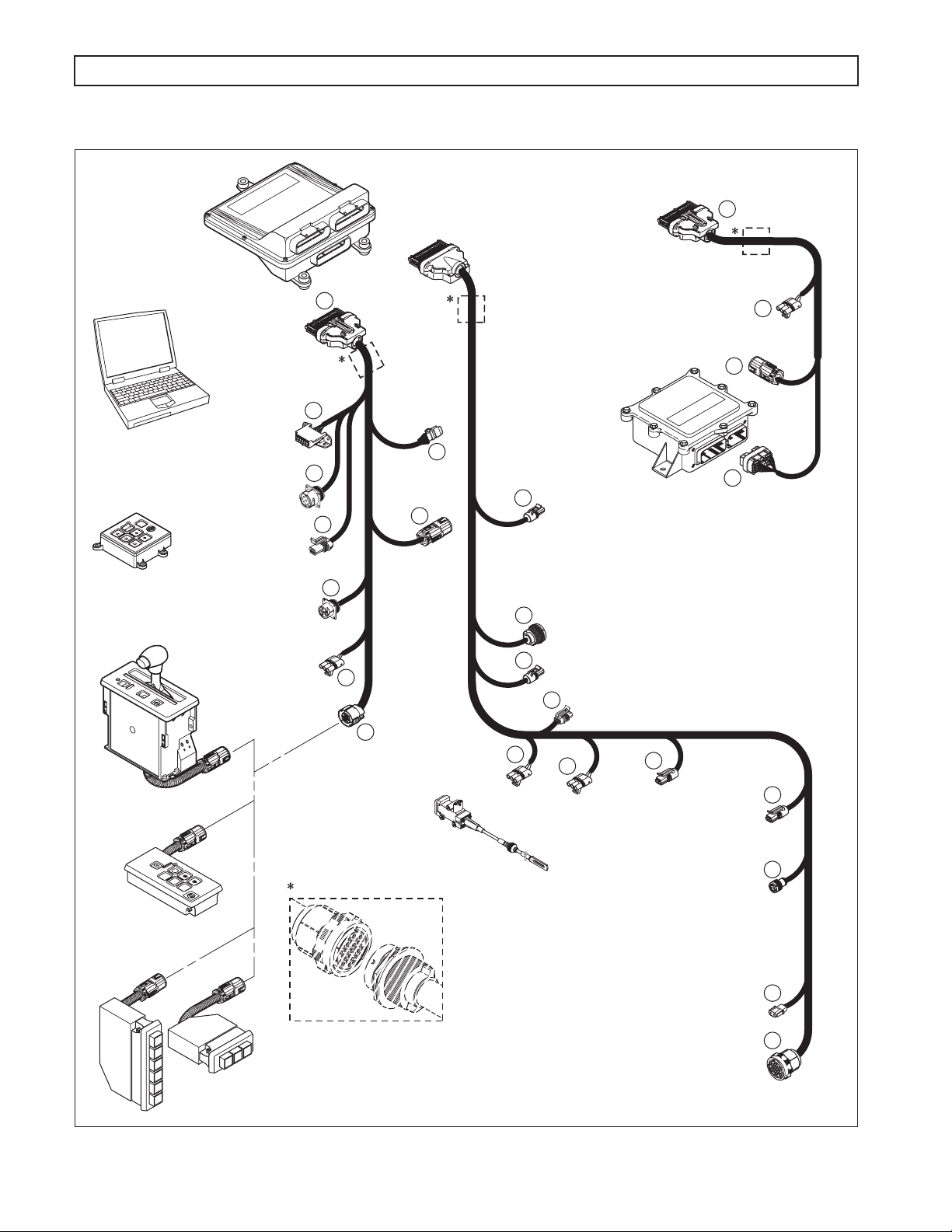
Figure 1–2 shows WTEC III electronic control components.
WTEC III Electronic Controls consist of the following elements:
•
Remote 12/24V Max Feature Sealed Electronic Control Unit (ECU)
Remote Pushbutton or Lever Shift Selector
•
•
Optional Secondary Shift Selector
OIL LEVEL SENSOR
SOLENOIDS
C3 PRESSURE SWITCH
TEMPERATURE SENSOR
(SUMP/RETARDER)
V03469
NOTE:
•
Throttle Position Sensor (TPS) (or electronic engine throttle data or PWM signal)
Engine, Turbine, and Output Speed Sensors
•
Control Module (Electro-Hydraulic Valve Body)
•
•
Wiring Harnesses
Vehicle Interface Module (VIM)
•
•
Autodetect Feature
•
TransID Feature
Optional Retarder Controls
•
•
Optional Engine Coolant Temperature Input.
All external harnesses are OEM supplied
•
•
The VIM is an OEM option
Copyright © 2005 General Motors Corp. 1–1
Page 11
WTEC III ELECTRONIC CONTROLS TROUBLESHOOTING MANUAL
R
MODE
N
D
BLUE
BLUE
BLACK
GRAY
GENERAL DESCRIPTION
ELECTRONIC
CONTROL
UNIT
(ECU)
ALLISON DOC
FOR PC
™
SELECTOR (S)
GRAY
TRANSMISSION (T)
BLACK
BLUE
BLUE
1
HARNESS
“T”
CONNECTOR
(BLUE)
VEHICLE (V)
HARNESS
“V”
CONNECTOR
(GRAY)
1
TPS
CONNECTOR
(OPTIONAL)
4
HARNESS
CONNECTOR
“S”
(BLACK)
VEHICLE
INTERFACE
MODULE
(VIM)
17
COMPACT
PUSHBUTTON
SELECTOR
MODE
REMOTE LEVER
SELECTOR
DIAGNOSTIC
TOOL
CONNECTOR
DEUTSCH 9-PIN
DIAGNOSTIC TOOL
CONNECTOR
SCI (J 1587)
CONNECTOR
(OPTIONAL)
DEUTSCH
DIAGNOSTIC TOOL
CONNECTOR
(OPTIONAL)
RETARDER
MODULATION
REQUEST (RMR)
CONNECTOR
25
17
19
17
18
J 1939
CONNECTOR
(OPTIONAL)
3
VIW
CONNECTOR
6
RETARDER ACCUMULATOR
CONNECTOR
7
SENSOR HARNESS
CONNECTOR (OPTIONAL)
OUTPUT
8
SPEED SENSOR
CONNECTOR
9
RETARDER TEMP. SENSOR CONNECTOR
16
REMOTE
PUSHBUTTON
SELECTOR
SELECT
SHIFT
SELECTOR
CONNECTOR
MODE
R
N
D
Bulkhead Connector (Optional)
THROTTLE POSITION
SENSOR (TPS)
CONNECTOR
THROTTLE
POSITION
SENSOR (TPS)
4
RMR
CONNECTOR
(OPTIONAL)
15
SPEED SENSOR
14
TURBINE
CONNECTOR
(4000 PRODUCT
FAMILY)
RETARDER “H” SOLENOID
(4000 PRODUCT FAMILY)
VIW
CONNECTOR
3
5
VIM
CONNECTOR
ENGINE
SPEED
SENSOR
CONNECTOR
CONNECTOR
13
13
STRIP PUSHBUTTON
SHIFT SELECTORS
(EUROPEAN
OEM)
(4000 PRODUCT FAMILY) PRE-TRANSID & TID 1
1
2
3
D
N
R
.
R
N
D
NOTE: Illustration is not to scale. Actual harness
configuration may differ from this illustration.
Figure 1–2. WTEC III Electronic Control Components
1–2 Copyright © 2005 General Motors Corp.
RETARDER TEMPERATURE
SENSOR CONNECTOR
TRANSMISSION
FEEDTHROUGH
HARNESS
CONNECTOR
11
10
V07347.04.00
Page 12
BLUE BLUE
BLACK GRAY
WTEC III ELECTRONIC CONTROLS TROUBLESHOOTING MANUAL
GENERAL DESCRIPTION
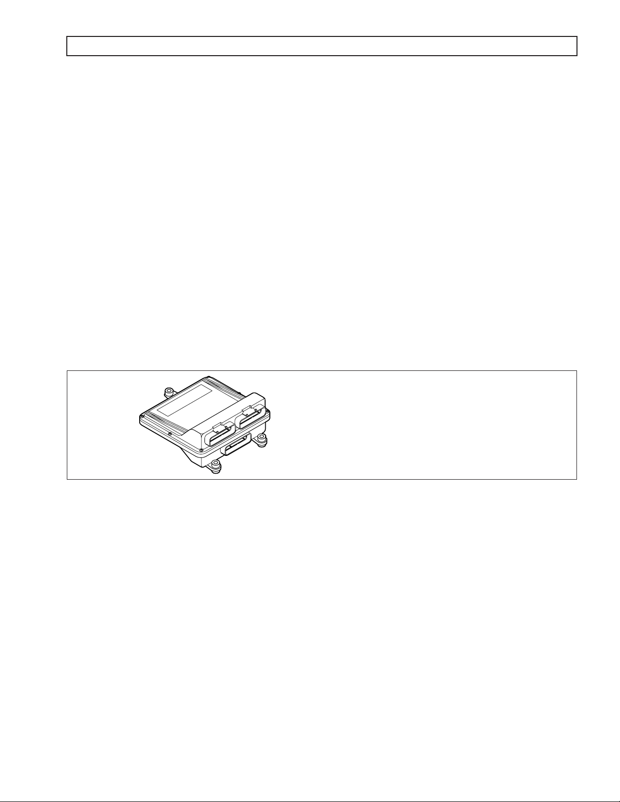
1–2. ELECTRONIC CONTROL UNIT (ECU)
The ECU (Figure 1–3) contains the microcomputer which is the brain of the control system. The ECU receives and
processes information defining:
Shift selector
•
•
Throttle position
•
Sump/retarder temperature
Engine speed
•
Turbine speed
•
•
Transmission output speed.
The ECU uses the information to:
•
Control transmission solenoids and valves
• Supply system status
• Provide diagnostic information.
Each ECU has a date code stamped on the label which is attached to the outer case of the ECU. This is the date
when the ECU passed final testing. This date is commonly used to denote the change configuration level of the
ECU. It is normal for the ECU date displayed electronically to be a few days prior to the date shown on the label.
NOTE: ECU wiring harness connector retainers are individually
keyed and color-coded to ensure that the proper
connector is attachedto the correct ECU socket.
The color of the connector retainer should
match the color of the connector strain relief
BLUE
ECU
Figure 1–3. Electronic Control Unit (ECU)
(see Appendix E, Paragraph 1–1).
V07346.00.01
1–3. SHIFT SELECTOR
Pushbutton and lever shift selectors for the WTEC III Series are remote mounted from the ECU and connected to
the ECU by a wiring harness. All shift selectors except the strip-type pushbutton have a single digit LED display
and a mode indicator (LED). During normal transmission operation, illumination of the LED mode indicator shows
that a secondary or special operating condition has been selected by pressing the MODE button. During diagnostic
display mode, illumination of the LED indicator shows that the displayed diagnostic code is active. Display
brightness is regulated by the same vehicle potentiometer that controls dash light display brightness. More
information on both types of shift selectors is continued below.
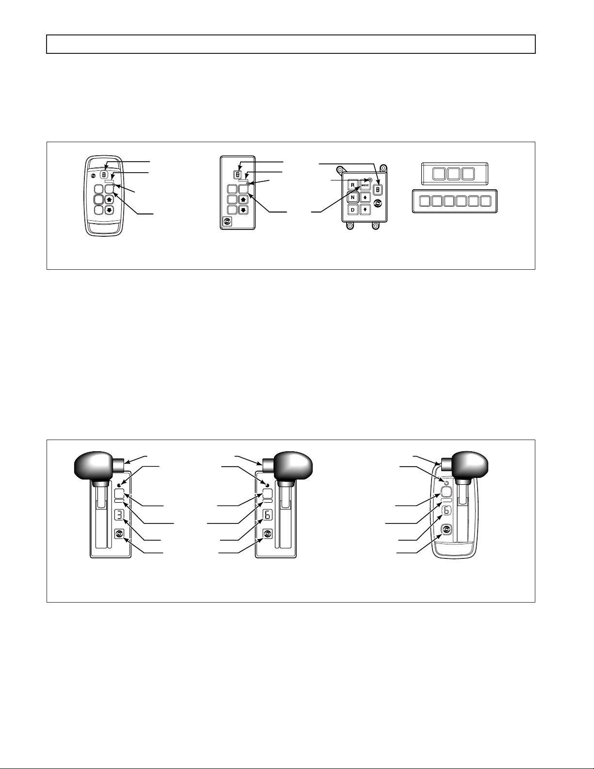
A. Pushbutton Shift Selector (Figure 1–4)
There are three full-function pushbutton shift selectors and a strip pushbutton shift selector. Strip
pushbutton shift selectors are used by European OEMs. A full-function shift selector has a MODE
button and diagnostic display capability through the single digit LED display. The strip pushbutton
shift selector does not have a MODE button, diagnostic capability, or adjustable illumination. The
full-function pushbutton shift selector has six (6) pushbuttons which are R (Reverse), N (Neutral),
D (Drive),
by pressing the
has a raised lip to aid in finding it by touch. The MODE button is pressed to select a secondary or
special operating condition, such as ECONOMY shift schedule. Diagnostic and oil level (if sensor is
present) information is obtained by pressing the
↓ (Down), ↑ (Up), and MODE. Manual forward range downshifts and upshifts are made
↓ (Down) or ↑ (Up) arrow buttons after selecting D (Drive). The N (Neutral) button
↓ (Down) and ↑ (Up) arrow buttons at the same time.
Copyright © 2005 General Motors Corp. 1–3
Page 13
WTEC III ELECTRONIC CONTROLS TROUBLESHOOTING MANUAL
GENERAL DESCRIPTION
The strip pushbutton shift selector has either three or six range selection positions as shown in Figure
1–4. When a strip pushbutton shift selector is used, diagnostic information must be obtained by using
the Allison DOC™ For PC–Service Tool, or a customer-furnished remote display.
DISPLAY
MODE ID
MODE
R
N
D
MODE INDICATOR
(LED)
MODE
BUTTON
CONTOURED VERSION
B. Lever Shift Selector (Figure 1–5)
The lever shift selector can have as many as six forward range positions (seven for the 7-speed
models), as well as R (Reverse) and N (Neutral). There is a hold override button which must be
pressed and held in order to move between certain selector positions. The hold override button must
be pressed when shifting between R, N, and D. The hold override button is released when the desired
selector position is reached. The selector lever can be moved freely between D and the numbered
forward ranges without pressing the hold override button. The lever selector can be chosen with the
lever on the left side or on the right side and with the R (Reverse) position toward the front or toward
the rear of the selector. Diagnostic and oil level (if sensor is present) information is obtained from the
LED display by pressing the DISPLAY MODE/DIAGNOSTIC button.
DISPLAY
MODE ID
MODE
R
N
D
MODE INDICATOR
(LED)
MODE
BUTTON
REGULAR COMPACT
PUSHBUTTON
SELECTORS
Figure 1–4. Pushbutton Shift Selectors
R
D
N
21 3DNR
STRIP PUSHBUTTON
SHIFT SELECTORS
V07178
HOLD OVERRIDE BUTTON
1
MODE
2
3
4
5
D
N
R
SIX-SPEED, LEFT-HAND
LEVER SELECTOR
WITH REVERSE TO REAR
MODE INDICATOR
(LED)
MODE BUTTON
MODE ID
DIGITAL DISPLAY
DISPLAY MODE/
DIAGNOSTIC BUTTON
Figure 1–5. Typical Lever Shift Selector
R
MODE
N
D
5
4
3
2
1
SIX-SPEED, RIGHT-HAND
LEVER SELECTOR
WITH REVERSE TO FRONT
HOLD OVERRIDE BUTTON
MODE INDICATOR
(LED)
MODE BUTTON
MODE ID
DIGITAL DISPLAY
DISPLAY MODE/
DIAGNOSTIC BUTTON
R
MODE
N
D
5
4
3
2
1
CONTOURED VERSION
V07177
1–4 Copyright © 2005 General Motors Corp.
Page 14
WTEC III ELECTRONIC CONTROLS TROUBLESHOOTING MANUAL
GENERAL DESCRIPTION
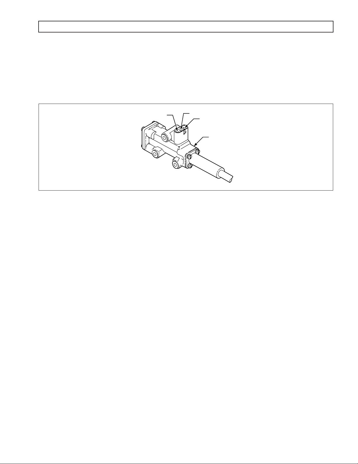
1–4. THROTTLE POSITION SENSOR (Figure 1–6)
The Throttle Position Sensor (TPS) can be mounted to the engine, chassis, or transmission. The TPS contains a pull
actuation cable and a potentiometer. One end of the cable is attached to the engine fuel lever and the other, inside a
protective housing, to the TPS potentiometer. Output voltage from the TPS is directed to the ECU through the
external harness. The voltage signal indicates the throttle position and, in combination with other input data,
determines shift timing.
A
Figure 1–6. Throttle Position Sensor (Without Mounting Brackets)
B
C
THROTTLE SENSOR
V00628
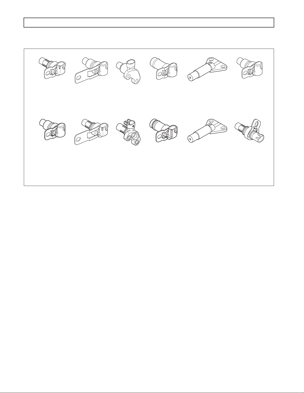
1–5. SPEED SENSORS (Figure 1–7)
The following three sensors provide information to the ECU:
• Engine speed−signal is generated by ribs on the torque converter pump.
• Turbine speed−signal is generated by the rotating-clutch housing spline contours.
• Output speed−signal is generated by a toothed member attached to the output shaft (except for the
3000 Product Family 7-speed models, where the toothed member is the transfer case idler gear).
The speed ratios between the various speed sensors allow the ECU to determine if the transmission is in the
selected range. Speed sensor information is also used to control the timing of clutch apply pressures, resulting in
the smoothest shifts possible. Hydraulic problems are detected by comparing the speed sensor information for the
current range to that range’s speed sensor information stored in the ECU memory.
Copyright © 2005 General Motors Corp. 1–5
Page 15
WTEC III ELECTRONIC CONTROLS TROUBLESHOOTING MANUAL
GENERAL DESCRIPTION
MD/HD/B 300/B 400
ENGINE
(EXTERNAL)
HD/B 500
TURBINE
(EXTERNAL)
MD/B 300/B 400
TURBINE
(INTERNAL)
MD/B 300/B 400
(EXCEPT 7-SPEED)
RETARDER OUTPUT
(EXTERNAL)
MD 3070PT
OUTPUT
(INTERNAL)
MD/HD/B
OUTPUT
(EXTERNAL)
FORMER (BEFORE APPROXIMATELY JANUARY 1, 2006
MD/HD/B
ENGINE
(EXTERNAL)
HD/B 500
TURBINE
(EXTERNAL)
MD/B 300/B 400
TURBINE
(INTERNAL)
MD/B 300/B 400
(EXCEPT 7-SPEED)
RETARDER OUTPUT
(EXTERNAL)
MD 3070PT 7-SPEED
OUTPUT
(INTERNAL HD)
MD/HD/B
OUTPUT
(EXTERNAL)
RETARDER
CURRENT (AFTER APPROXIMATELY JANUARY 1, 2006)
SENSORS
Figure 1–7. Speed Sensors
V09818.00.00
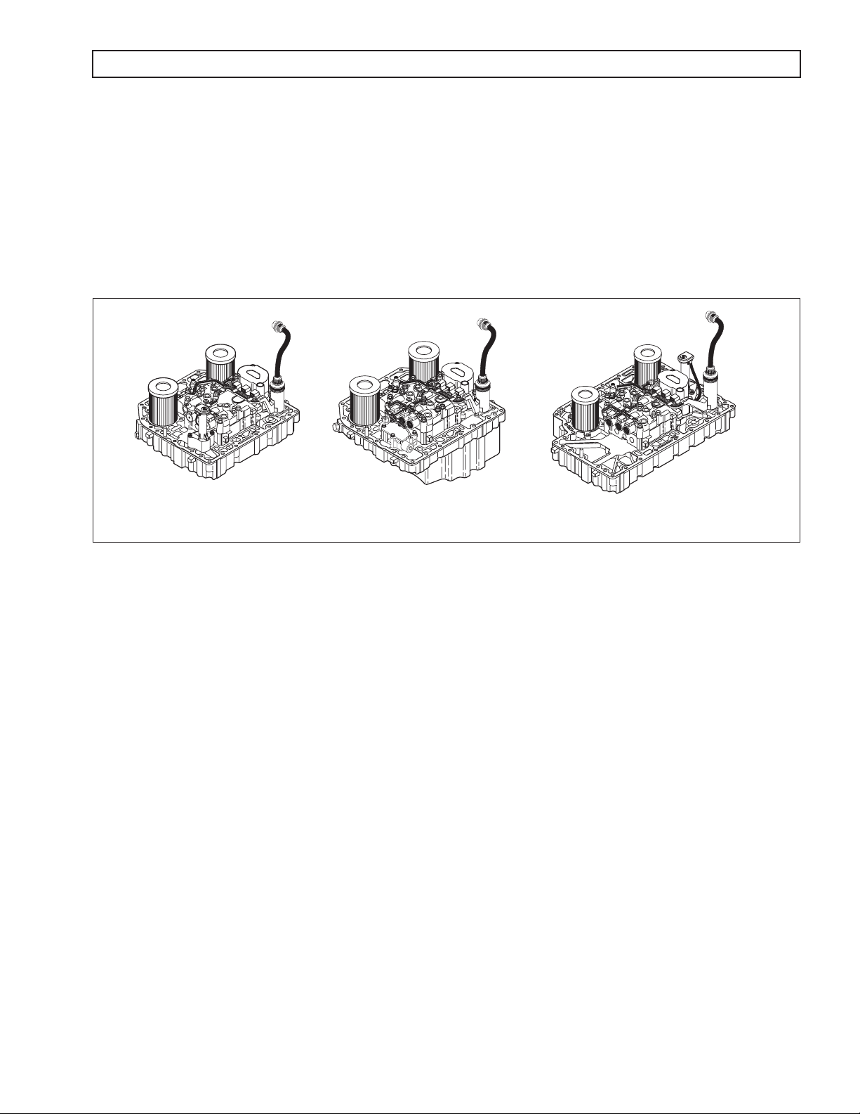
1–6. CONTROL MODULE (Figure 1–8)
Pulse width modulated solenoids are used in the valve bodies. For valve locations, refer to SIL 27-WT-93.
The WTEC III Series transmission control module contains a channel plate on which is mounted a:
• Main valve body assembly.
• Stationary-clutch valve body assembly.
• Rotating-clutch valve body assembly.
The main valve body assembly contains:
• G solenoid and the C1 and C2 latch valves controlled by the solenoid.
• Main and lube regulator valves.
• Control main and converter regulator valves.
• Converter flow valve and exhaust backfill valves.
The stationary-clutch valve body assembly contains:
• C solenoid (C3)
• D solenoid (C4)
• E solenoid (C5)
• Solenoid regulator valves controlled by the solenoids
• C3 accumulator relay valve
1–6 Copyright © 2005 General Motors Corp.
Page 16
WTEC III ELECTRONIC CONTROLS TROUBLESHOOTING MANUAL
GENERAL DESCRIPTION
The rotating-clutch valve body assembly contains:
• A solenoid (C1)
• B solenoid (C2)
• F solenoid (lockup)
• Solenoid regulator valves controlled by the solenoids
• C3 pressure switch
The low valve body assembly (3000 and 4000 Product Families 7-speed) contains N and J solenoids.
3000 PRODUCT FAMILY CONTROL MODULE
(EXCEPT 7-SPEED MODELS)
3000 PRODUCT FAMILY 7-SPEED 4000 PRODUCT FAMILY CONTROL MODULE
V07349.00.00
Figure 1–8. WTEC III Control Modules
A temperature sensor (thermistor) is located in the internal wiring harness. Changes in sump fluid temperature are
indicated by changes in sensor resistance which changes the signal sent to the ECU. Refer to Figure 6–8 in
Section 6, Code 24.
The oil level sensor (OLS) is a float type device mounted on the control module channel plate. The OLS senses
transmission fluid level by electronically measuring the buoyancy forces on the float. The sensor operates on
5 VDC supplied by the ECU. The oil level sensor is standard on 3000 and 4000 Product Families transmissions.
An OLS is required on all models with a shallow sump but is optional on other models. The oil level sensor is not
available on the 3000 Product Family 7-speed models.
The C3 pressure switch is mounted on the rotating-clutch valve body assembly and indicates when pressure exists
in the C3 clutch-apply passage. An accumulator/relay valve is in-line ahead of the C3 pressure switch and prevents
high frequency hydraulic pulses generated by the C3 solenoid from cycling the C3 pressure switch.
Also mounted on the control module is the turbine speed sensor for the 3000 Product Family transmissions. The
turbine speed sensor is directed at the rotating-clutch housing. The turbine speed sensor on the 4000 Product
Family transmissions is located on the outside of the main housing.
Copyright © 2005 General Motors Corp. 1–7
Page 17

WTEC III ELECTRONIC CONTROLS TROUBLESHOOTING MANUAL
GENERAL DESCRIPTION
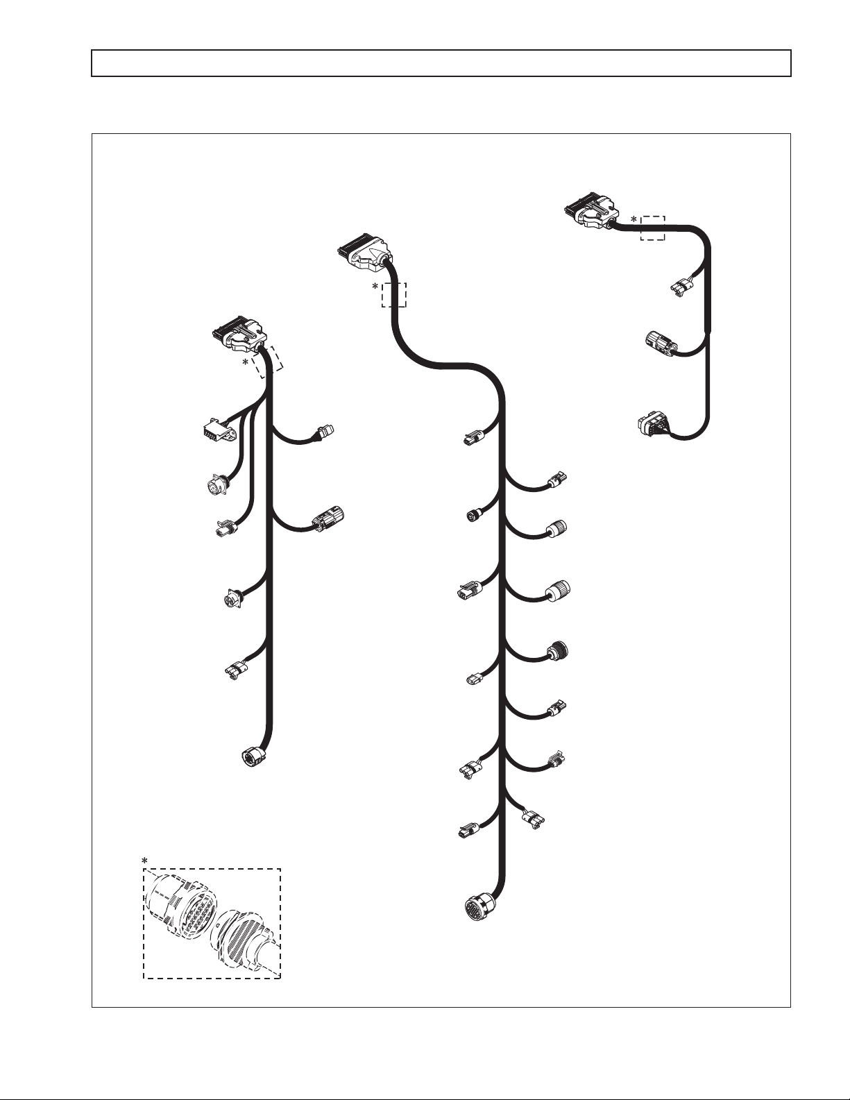
1–7. WIRING HARNESSES
A. External Wiring Harness (Figure 1–9)
The ECU uses three connectors labeled Black, Blue, and Gray, which are used to receive input from
the following:
Transmission TPS Diagnostic tool connector
Engine Vehicle interface module (VIM) Retarder
Turbine Retarder control module Retarder temperature sensor
Output speed sensor Shift selector Accumulator
Many harnesses will include a bulkhead fitting to separate cab and chassis components. Also, many
different styles and materials for harnesses are likely to be encountered.
NOTE: Allison Transmission is providing for service of wiring harnesses and wiring harness components as
follows:
• Repair parts for the internal wiring harness and for wiring harness components attached to the
shift selector will be available through the Allison Transmission Parts Distribution Center (PDC).
Use the P/N from your appropriate parts catalog or from Appendix E in this manual. Allison
Transmission is responsible for warranty on these parts.
• Repair parts for the external harnesses and external harness components must be obtained from St.
Clair Technologies Inc. (SCTI). SCTI provides parts to any Allison customer or OEM and is
responsible for warranty on these parts. SCTI recognizes Allison Transmission, manufacturers,
and SCTI part numbers. SCTI provides a technical HELPLINE at 519-627-1673 (Wallaceburg).
SCTI will have parts catalogs available. The SCTI addresses and phone numbers for parts outlets
are:
St. Clair Technologies, Inc.
920 Old Glass Road
Wallaceburg, Ontario, Canada N8A 4L8
Phone: 519-627-1673
Fax: 519-627-4227
• St. Clair Technologies, Inc. stocks a WTEC III external harness repair kit, P/N 29532362, as a
source for some external harness repair parts. SCTI is the source for external harness repair parts.
St. Clair Technologies, Inc.
Calle Damanti S/N Col
Guadalupe—Guaymas
Sonora, Mexico CP85440
Phone: 011-526 2222-43834
Fax: 011-526-2222-43553
1–8 Copyright © 2005 General Motors Corp.
Page 18
WTEC III ELECTRONIC CONTROLS TROUBLESHOOTING MANUAL
GENERAL DESCRIPTION
VEHICLE (V)
HARNESS
TRANSMISSION (T)
HARNESS
“V”
CONNECTOR
(GRAY)
RETARDER
ACCUMULATOR
CONNECTOR
TRANSFER
CASE
CONNECTOR
(3000 PRODUCT FAMILY
7–SPEED)
RETARDER
CONNECTOR
(3000 PRODUCT FAMILY)
PRE-TRANSID & TID 1
SENSOR HARNESS
CONNECTOR
(OPTIONAL)
OUTPUT
SPEED SENSOR
CONNECTOR
TPS
CONNECTOR
(OPTIONAL)
VIW
CONNECTOR
VIM
CONNECTOR
SELECTOR (S)
HARNESS
CONNECTOR
DIAGNOSTIC
CONNECTOR
DEUTSCH 9-PIN
DIAGNOSTIC TOOL
DIAGNOSTIC TOOL
6–PIN CONNECTOR
REQUEST (RMR)
“S”
(BLACK)
TOOL
CONNECTOR
SCI (J 1587)
CONNECTOR
(OPTIONAL)
DEUTSCH
(OPTIONAL)
RETARDER
MODULATION
CONNECTOR
J 1939
CONNECTOR
(OPTIONAL)
“H” SOLENOID
(4000 PRODUCT
VIW
CONNECTOR
“H” SOLENOID
(3000 PRODUCT FAMILY)
TEMPERATURE SENSOR
(4000 PRODUCT FAMILY)
PRE-TRANSID & TID 1
“T”
CONNECTOR
(BLUE)
ENGINE
SPEED
SENSOR
CONNECTOR
RETARDER
CONNECTOR
FAMILY)
RETARDER
CONNECTOR
TID 2
RETARDER
CONNECTOR
SHIFT
SELECTOR
CONNECTOR
Bulkhead Connector (Optional)
RMR
CONNECTOR
(OPTIONAL)
TURBINE
SPEED SENSOR
(4000 PRODUCT FAMILY)
NOTE: Illustration is not to scale. Actual harness configuration may differ from this illustration.
CONNECTOR
TRANSMISSION
FEEDTHROUGH
HARNESS
CONNECTOR
RETARDER TEMPERATURE
SENSOR CONNECTOR
(3000 PRODUCT FAMILY)
TID 2
THROTTLE POSITION
SENSOR (TPS)
CONNECTOR
V07086.04.00
Figure 1–9. WTEC III External Wiring Harnesses
Copyright © 2005 General Motors Corp. 1–9
Page 19
WTEC III ELECTRONIC CONTROLS TROUBLESHOOTING MANUAL
GENERAL DESCRIPTION
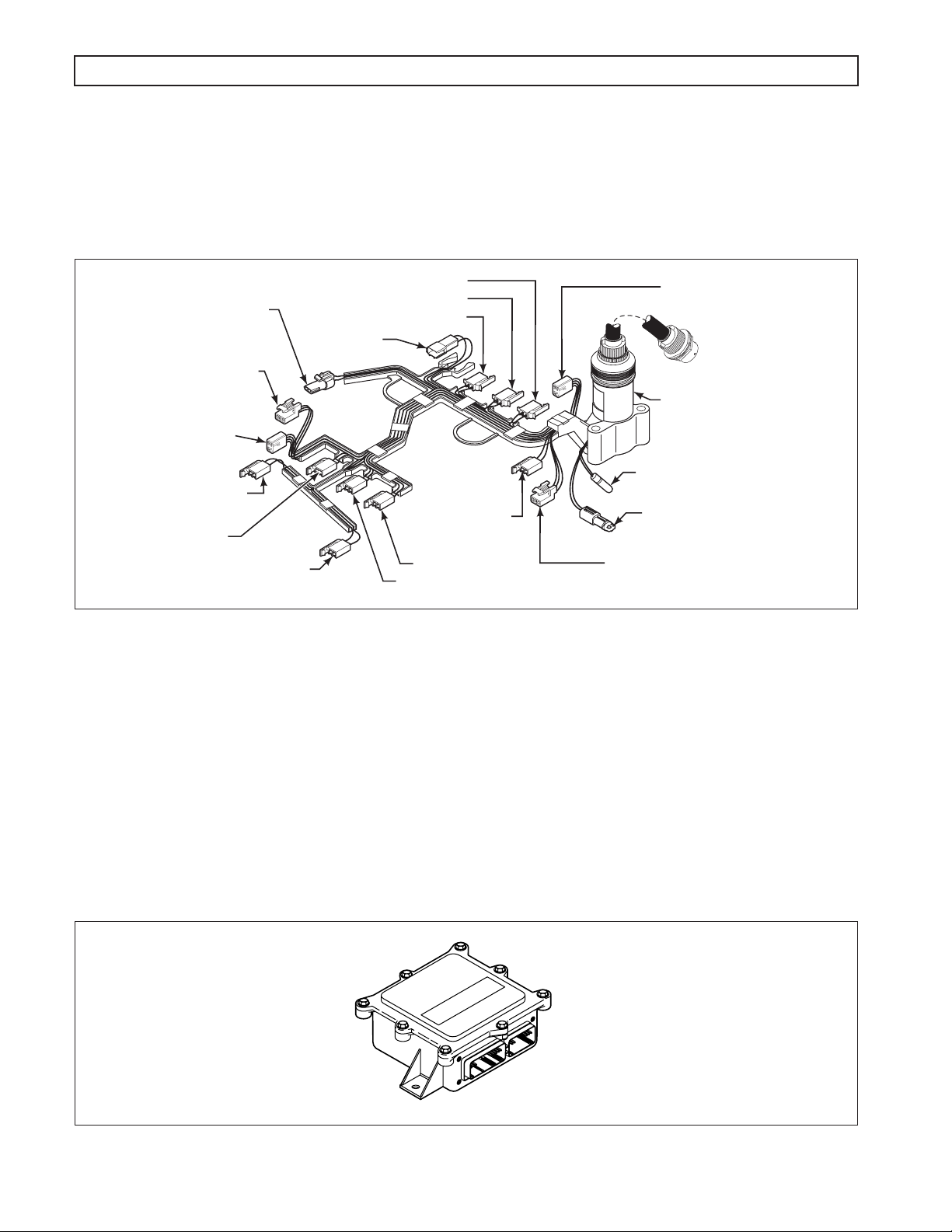
B. Internal Wiring Harness (Figure 1–10)
The internal wiring harness provides connection between the external harness, the pulse width
modulated solenoids, oil level sensor, C3 pressure switch, and the temperature sensor.
TURBINE SPEED SENSOR
3000 PRODUCT FAMILY
(Omitted in 4000 Product Family)
OIL LEVEL SENSOR
3000 PRODUCT FAMILY
(Starting with S/N 6510220479)
OIL LEVEL SENSOR
3000 PRODUCT FAMILY
(Before S/N 6510220479)
LO SIGNAL SOLENOID (N)
3000 AND 4000 PRODUCT
FAMILIES 7-SPEED
C4 SOLENOID (D)
C6 SOLENOID (J)
3000 AND 4000 PRODUCT
FAMILIES 7-SPEED
C3 PRESSURE
C2 SOLENOID (B)
LU SOLENOID (F)
C1 SOLENOID (A)
SWITCH
FORWARD
SOLENOID (G)
C5 SOLENOID (E)
C3 SOLENOID (C)
Figure 1–10. WTEC III Internal Wiring Harness
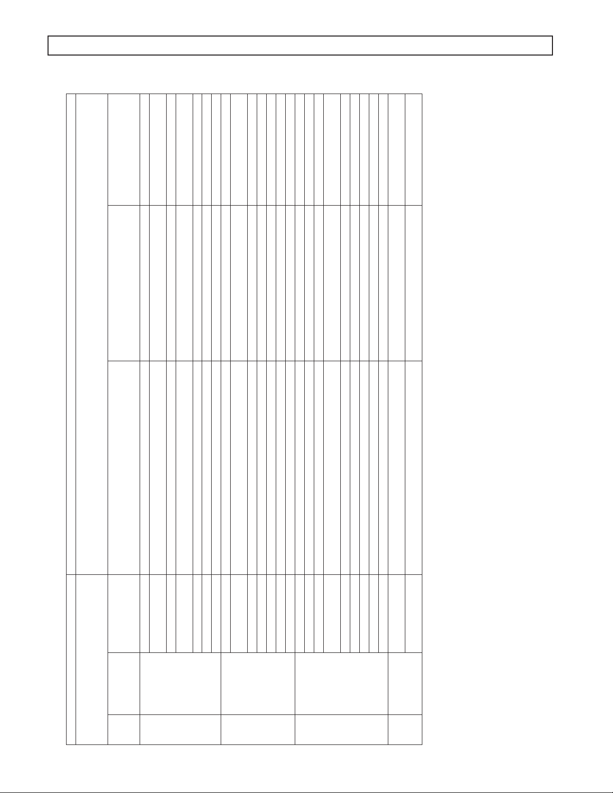
1–8. VEHICLE INTERFACE MODULE (Figure 1–11)
OIL LEVEL SENSOR
4000 PRODUCT FAMILY
(Before S/N 6610048466)
FEEDTHROUGH HARNESS
STANDOFF
(3000 and 4000
Product Families
are different heights)
TEMPERATURE SENSOR –
TRANSID 1
TEMPERATURE SENSOR –
TRANSID 2
OIL LEVEL SENSOR
4000 PRODUCT FAMILY
(Starting with S/N 6610048466)
V07381.02.00
The vehicle interface module (VIM) provides relays, fuses, and connection points for interface with
the output side of the vehicle electrical system. VIMs are available for both 12V and 24V electrical
systems. The VIM for 12V systems uses all 12V relays. The VIM for 24V systems has all 24V relays.
Refer to the Parts Catalog for the transmission assembly number that you are servicing for detailed
parts information. Refer to Pages D–30 and D–31 for VIM wire number and terminal information.
Some OEMs may provide their own equivalent for the VIM which performs the same functions as the
VIM shown in Figure 1–11.
Figure 1–11. Vehicle Interface Module (VIM)
1–10 Copyright © 2005 General Motors Corp.
V00631.02
Page 20

WTEC III ELECTRONIC CONTROLS TROUBLESHOOTING MANUAL
GENERAL DESCRIPTION
1–9. AUTODETECT FEATURE (V8, V8A, V9 SOFTWARE)
Autodetect is active on the first 24 engine starts or a larger calibration number of engine starts, depending upon the
component or sensor being detected (details follow in A through D below). Autodetect takes place within the first
30 seconds of each engine start monitored. Autodetect searches for the presence of the following transmission
components or data inputs:
Retarder Present, Not Present
Oil level sensor (OLS) Present, Not Present
Throttle Analog, J1939, J1587
Engine coolant temperature Analog, J1939, J1587
Even after auotdetect has been completed, it can be reset to monitor an additional group of engine starts. Reset may
be necessary if a device known to be present is not detected or if an autodetectable component or sensor was added
after the initial vehicle build. Reset is accomplished by using Allison DOC™
AUTODETECT INFORMATION.” Allison DOC™
and manually enter the component or sensor to be recognized by the ECU by changing appropriate “customer
modifiable constants”.
For PC–Service Tool can also be used to override autodetect
For PC–Service Tool. Select “RESET
The four items above are the only customer modifiable constants (CMCs) that are autodetected. Other CMCs can
be changed at any time and are not related to autodetect. Consult Allison publication GN3433EN, User Guide, for
detailed instructions related to WTEC III “customer modified constants.” Additional details for each of the four
autodetectable features are given below.
A. Retarder
Autodetect searches for the presence of the H (retarder) solenoid during the first 24 engine ignition
cycles. The H solenoid must be present on the 24th engine start or the retarder is not detected and
will not function on subsequent engine starts.
If the retarder is present but not detected by autodetect, the retarder will not function. Be
sure to test for proper retarder function immediately after the 24th engine start. If the
WARNING
B. Oil Level Sensor (OLS)
NOTE: If an OLS is known to be present, but has not been detected, a possible cause is that the transmission
fluid level is too low. Determine the fluid level before beginning OLS troubleshooting.
retarder is not functioning, test H solenoid for open, short-to-ground, or short-to-battery
condition. Use Allison DOC™ For PC–Service Tool to reset autodetect or to manually
select the presence of the retarder after the H solenoid circuit is repaired.
No oil level sensor diagnostics take place until the OLS is detected. Frequently test for the presence of
oil level diagnostics if the transmission is known to contain an OLS. If an OLS is not detected during
the first 24 engine starts, autodetect continues for a larger calibration number of engine starts.
Autodetect stops when an OLS is detected or when the calibration number of starts is reached. When
the larger calibration number of engine starts is reached, the ECU concludes that no OLS is present. If
an OLS is known to be present, but has not been detected, troubleshooting the OLS circuit is required.
After the OLS circuit is repaired, reset autodetect or manually select the OLS function using Allison
DOC™ For PC–Service Tool.
Copyright © 2005 General Motors Corp. 1–11
Page 21

WTEC III ELECTRONIC CONTROLS TROUBLESHOOTING MANUAL
GENERAL DESCRIPTION
C. Throttle Source (V8, V8A Software—See Paragraph 1–10C For V9A)
Whenever autodetect is functioning and no throttle source is found, a code 26 00 is logged. If a
datalink throttle source (J 1939 and J 1587) is detected, autodetect stops looking for that function.
However, if no analog throttle source was detected prior to engine start 25, autodetect continues for
engine starts 25 through a calibration number. Autodetect for analog throttle stops as soon as a device
is detected or when the calibration number of starts is reached. If an analog throttle source is known
to be present, but is not detected, troubleshooting of the analog throttle circuit is required. After the
analog throttle circuit is repaired, reset autodetect or manually select the analog throttle function
using Allison DOC™ For PC–Service Tool. An engine throttle source must be present.
A pulse width modulated (PWM) throttle source requires an unique calibration or must be manually
selected using Allison DOC™ For PC–Service Tool.
D. Engine Coolant Temperature Sensor Source
Autodetect looks for an engine coolant temperature source during the first 24 engine starts. However,
code 26 11 is not logged unless the calibration calls for engine coolant temperature data to be used for
retarder capacity reduction or preselected downshifts due to retarder overheating. Autodetect
remembers whatever engine coolant temperature source was present on engine start 24. If no analog
engine coolant temperature source is found on engine start 24, autodetect concludes that no sensor is
present. Therefore, if an engine coolant temperature source is known to be present at engine start 24,
but is not detected, troubleshooting of the engine coolant temperature circuit is required. After the
engine coolant temperature circuit is repaired, reset autodetect or manually select the engine coolant
temperature function using Allison DOC™ For PC–Service Tool.
1–10. AUTODETECT FEATURE (V9A, V9B, AND V9C SOFTWARE)
A. Retarder
Retarder autodetect software version V9A will countdown for a maximum of 25 ignition cycles while
recording detections of a retarder.
Retarder autodetect software version V9B and V9C will countdown for a maximum of 35 ignition
cycles while recording detections of a retarder.
A retarder will be identified as present and the retarder autodetect logic will stop once it is detected
for three consecutive ignition cycles. If the ignition cycle counter completes the 25 cycles (V9A) or
35 cycles (V9B, V9C) before there are three consecutive detections of a retarder, the software will log
that there is not retarder present and the retarder autodetect logic will stop.
B. Oil Level Sensor (OLS)
OLS autodetect will countdown for a maximum of 25 engine starts while recording detections of an
OLS. An OLS will be identified as present and the OLS autodetect logic will stop once it is detected
for:
• Five consecutive engine starts for software version V9A
• Three consecutive starts for software version V9B
• One engine start for software version V9C.
If the engine start counter completes 25 cycles before an OLS is detected (depending on the software
version specifications above), the software will log that there is not OLS present and the OLS
autodetect logic will stop. OLS detection must occur within 12.5 seconds on any given engine start.
1–12 Copyright © 2005 General Motors Corp.
Page 22

WTEC III ELECTRONIC CONTROLS TROUBLESHOOTING MANUAL
GENERAL DESCRIPTION
Software version V9C will autodetect before an engine start if accumulated counts are greater than
100 or after an engine start if accumulated counts are greater than 25 but less than 100. No autodetect
occurs if accumulated counts are less than 25.
C. Throttle Source (Also Applies to V9 Software)
Throttle autodetect will increment a counter for a throttle source on each engine start during which
the possible throttle source is detected. When the counter for any of the sources indicates five
consecutive detections, the software will set a “confidence flag” to indicate that this is an available
throttle source. Multiple throttle sources can be detected on a single engine start and multiple
confidence flags can be set. There is no limit to the number of engine starts for autodetection of the
throttle source until a confidence flag is set for a source. Once a confidence flag is set for any one of
the sources, a counter begins to countdown for 15 additional engine starts. During the entire
autodetect period, the software will use the highest priority source as the throttle source if multiple
sources are detected before any confidence flags are set. Once a confidence flag is set, that source is
used as the source for the throttle signal. When the countdown period is complete, the software will
use the highest priority throttle source having a confidence flag set and the autodetect logic will stop.
D. Engine Coolant Temperature
Engine coolant temperature sensor autodetect will countdown for a total of 25 engine starts while
recording detections of engine coolant temperature sources. A “confidence flag” will be set once a
source is detected for five consecutive engine starts. Multiple sources detected before a confidence
flag is set or multiple confidence flags will result in the highest priority source being used as the
engine coolant temperature source. Multiple sources can be detected on a single engine start cycle.
1–11. TRANSID FEATURE
A. General Description
The TransID feature has been provided so that Allison Transmission can make component changes
which require calibration changes but still retain both the original transmission assembly number
(A/N) before feature based ordering (FBO) and the original calibrated ECU A/N. The purpose of
TransID is to reduce the need for OEMs to use cross-reference lists of transmission and calibrated
ECU A/Ns when such changes to the transmission are made. Since FBO began in April, 1998, the
OEM now needs to be sure the ECU being used is compatible with the TransID level stamped on the
nameplate of the transmission.
The basis for the TransID system is the creation of a TransID wire in the WTEC III system to provide
the signal to the ECU of the TransID level of the transmission. This wire will at first be connected
directly to the Analog Return (wire 135) to signal TransID level 1 (TID 1). TransID levels 2 through 8
will then be indicated by connecting the TransID wire in sequence to the return of solenoids A, B, C,
D, E, G, and F. Corresponding to the hardware changes is the ability in the V8A and later WTEC III
ECU to contain up to eight calibrations. The connection point of the TransID wire will provide the
signal to tell the ECU which calibration is required by the transmission.
Whenever a TransID level change is to be made, the new TransID level calibrations will be placed in
the PROM Calibration Configurator System (PCCS) before the change(s) is (are) made in production
to the transmissions. All ECUs programmed and sold after that date will then be loaded with the new
TransID level calibration. These ECUs will contain calibrations for the new level transmission and all
previous TransID levels and will automatically load the correct calibration for the transmission based
on the TransID signal sensed by AutoDetect during the first 25 engine starts. This eliminates worry on
the part of the OEM of coordinating the implementation of the new ECU and the new transmission
and allows their focus to be on using the stock of the earlier level ECU.
Copyright © 2005 General Motors Corp. 1–13
Page 23

WTEC III ELECTRONIC CONTROLS TROUBLESHOOTING MANUAL
GENERAL DESCRIPTION
B. Transmission Changes Versus TransID Number
1. TransID 1
The internal wiring harness wiring change to make a TransID 1 (TID 1) transmission was put into
production before the introduction of the WTEC III system. The TID 1 internal harness was made
by connecting the C3 pressure switch ground (digital/signal ground; WTEC II wire 161) to the
sump temperature sensor and OLS ground (analog ground; wire 135) in the internal harness. In
WTEC II, the signal ground wire (wire 161) is routed through the transmission connector, terminal
W, and then to the ECU, terminal B27. In WTEC III, this same wire in the internal harness
becomes the TID wire (wire 195), and it goes to the ECU, terminal T13 (blue connector). The
purpose of TID 1 was to provide a common transmission for use with both WTEC II and
WTEC III systems (V7A and V8).
The only difference between a pre-TID transmission and a TID 1 transmission is the internal
wiring harness which connects the digital and analog grounds on the TID 1 harness. Adapter
harness P/N 200100 can be ordered from St. Clair Technologies to provide the same connection
outside the transmission and allow a pre-TransID transmission to be “converted” to a TransID 1
transmission.
All models of the 3000 and 4000 Product Families transmissions were built with the TID 1 internal
(feedthrough) harness beginning in September, 1996. Two changes were rolled into this update: the
wiring change for TID 1 and a change to use a molded channel rather than the braided covering
which was previously used. Both changes were rolled into the same internal harness P/N even
though there was a delay in implementing the channel which resulted in the two serial number (S/N)
breaks. Table 1–1 lists the harness P/Ns for the different transmission models along with the S/Ns
for both changes for each harness.
Table 1–1. TransID 1 S/N Breakpoint
Pre-TransID
Transmission Model
3000 Product Family w/ OLS 29516322 29529472 6510088864 6510096671
3000 Product Family w/o OLS 29516323 29529473 6510089316 6510096683
3000 Product Family 7-Speed 29516324 29529474 6510090786 6510096675
4000 Product Family w/ OLS 29516325 29529475 6610014067 6610015591
4000 Product Family w/o OLS 29516326 29529476 6610014084 6610015700
4000 Product Family 7-Speed N/A N/A N/A N/A
*NOTE: These P/Ns are no longer serviced, refer to Table 1–4 for current P/Ns.
2. TransID 2
The purpose of the TransID 2 (TID 2) change is to indicate the use of new sump and retarder
temperature sensors (thermistors) and a new 3000 Product Family retarder design. The new
retarder requires a different calibration than the old retarder. Retarder performance complaints will
occur if the new retarder is controlled by the old retarder calibration or the old retarder is
controlled by the new retarder calibration.
TID 2 internal harnesses contain both the new sump temperature sensor and a new connection
point for the TID wire. The TID wire (195) is connected to Solenoid A ground (wire 120) to signal
TID 2 to the ECU. The new temperature sensors are discussed below.
A TID 2 transmission will only work with a V8A or later ECU (WTEC III) and V8A and later
ECUs are calibrated to accommodate both TID 1 and TID 2 transmissions. The 4000 Product
Family 7-Speed transmissions were equipped with TID 2 at the start of production. The 3000 and
4000 Product Families transmissions produced before April 3, 2000 were TID 2 units.
Harness P/N*
TransID 1
Harness*
S/N at Wiring
Change
S/N at
U-Channel
1–14 Copyright © 2005 General Motors Corp.
Page 24

WTEC III ELECTRONIC CONTROLS TROUBLESHOOTING MANUAL
GENERAL DESCRIPTION
The internal harness change to all models for TID 2 production began in late December, 1997.
The S/N breakpoints are shown in Table 1–2.
Table 1–2. TransID 2 S/N Breakpoint
Transmission Model
TransID 1
Harness P/N*
TransID 2
Harness P/N*
S/N at Thermistor and
Wiring Change
3000 Product Family w/ OLS 29529472 29533652 6510141464
3000 Product Family w/o OLS 29529473 29533653 6510141470
3000 Product Family 7-Speed 29529474 29533654 6510142172
4000 Product Family w/ OLS 29529475 29533655 6610026328
4000 Product Family w/o OLS 29529476 29533656 6610026319
4000 Product Family 7-Speed N/A 29533657
*NOTE: These P/Ns are no longer serviced, refer to Table 1–4 for current P/Ns.
6610034908
(start of production)
The new retarder thermistor used on TID 2 retarder model transmissions has a molded connector
and is the same on all TID 2 retarders. The TID 1 and pre-TID retarder thermistor had a two
terminal connector attached to it when it was used on 4000 Product Family transmissions. It was
part of a retarder harness assembly when used on 3000 Product Family transmissions. Refer to
Appendix Q which describes the new and old temperature sensors. A graph and a table of
resistance values for different temperatures are also included in Appendix Q.
Table 1–3 shows the old (pre-TID and TID 1) and the new (TID 2) part numbers of the retarder
temperature sensors and the serial number when the change was made.
Table 1–3. New Retarder Temperature Sensor S/N Breakpoint
Transmission Model Former Thermistor Used
P/N Where
Former
Thermistor Used
New
Thermistor
P/N (TID 2)
First S/N
For New
Thermistor
3000 Product Family built into retarder harness 29510662 15326309 6510142059
4000 Product Family built with connector attached 29511861 15326309 6610026472
3. TransID 3
Starting April 3, 2000, the TID feature was changed from TID 2 to TID 3. A new internal harness
was released to implement the TID 3 feature. Figure J–3 (Appendix J) shows the wiring schematic
for the new internal harness. TID 1 and TID 2 internal harnesses have been maintained for service
units built before April 3, 2000. TID 3 is required to make sure that the auto-detect feature selects
the proper calibration for the new friction plate material.
Version 8A software was updated to include TID 3 capability as of October 1999. Table 1–4 shows
the new internal harness part numbers for each of the control module configurations. Also
reference Table 1–5 for transmission/ECU compatibility information. The 3000 and 4000 Product
Families transmissions produced starting April 3, 2000 were TID 3 units. All T Series
transmissions were TID 3 at introduction.
Copyright © 2005 General Motors Corp. 1–15
Page 25

WTEC III ELECTRONIC CONTROLS TROUBLESHOOTING MANUAL
GENERAL DESCRIPTION
†
Table 1–4. Current Internal Harness Service Kit
3000 and 4000 Product Families Internal Harness Service Kits
Transmission
TransID 1 TransID 2 ** TransID 3***
3000 Product Family w/o OLS 29542683 29542680 29542660
3000 Product Family w/ OLS (old)* 29542682 29542677 N/A
3000 Product Family w/ OLS (new)* 29542651 29542671 29542681
3000 Product Family 7-Speed 29542684 29542679 29542687
4000 Product Family w/o OLS 29542686 29542649 29542688
4000 Product Family w/ OLS (old)* 29542685 29542648 N/A
4000 Product Family w/ OLS (new)* 29544141 29542670 29542689
4000 Product Family 7-Speed w/o OLS N/A 29542650 29542690
4000 Product Family 7-Speed w/ OLS N/A N/A 29542691
* Reference SIL 19-WT-99
** Reference SIL 7-WT-98
*** Reference SIL 4-WT-00 N/A Not Applicable
† The key words associated with this reference are “current” and “kits”.
C. Compatibility Between TransID Level And ECU Calibration Level
Table 1–5 shows the compatibility of the different ECU software levels with the different TID level
transmissions.
Table 1–5. ECU/TransID Compatibility
P/N by TransID Version
WTEC II
WTEC III
CIN Compatibility
Number
Software
Level
Compatible with
TransID Level
ECU Production
Dates
07 V6E pre-TID and TID 1 until 9/94
08 V7 and V7A pre-TID and TID 1 9/94 until 12/97
0A V8 TID 1 2/97 until 9/97
0B V8A TID 1 and 2 beginning 10/97
0C V9 TID 1, 2, and 3 beginning 4/00
0D V9A TID 1, 2, and 3 beginning 4/01
The manufacture and sale of both WTEC II and WTEC III ECUs during most of 1997 required a
means of using a common transmission with either a WTEC II or a WTEC III ECU. A TID 1
transmission is the common transmission configuration for both control systems and production
began in September, 1996 (refer to Table 1–3). A TID level 1 transmission is compatible with any
Allison-supplied ECU.
Pre-TransID transmissions are only compatible with V6E, V7, and V7A ECUs. Pre-TransID
transmissions were produced before the first S/N break in Table 1–3.
TransID level 2 transmissions were produced beginning in late December, 1997 (refer to
Table 1–5). A TransID 2 transmission is compatible with V8A and later ECUs only.
TransID level 3 transmissions were produced beginning April 3, 2000 (refer to Table 1–5). A
TransID 3 transmission is compatible with V8A and later ECUs only. Software V9 or V9A is required
to use Reduced Engine Load at Stop (RELS). Refer to Table 1–6 for S/N break points.
Table 1–6. TID 3 S/N Break Point
Model S/N Break
3000 Product Family 6510262117
4000 Product Family 6610062126
1–16 Copyright © 2005 General Motors Corp.
Page 26

WTEC III ELECTRONIC CONTROLS TROUBLESHOOTING MANUAL
GENERAL DESCRIPTION
The following table shows compatibility information between transmission and vehicle configuration.
Vehicle Configuration (ECU, Shifter, and Wiring)
Transmission
Configuration
Pre-TID 3000 and 4000
Product Families;
Raybestos plates only
TID1: 3000 and 4000
Product Families;
Raybestos plates only
TID2: 3000 and 4000
Product Families; New
style sump and retarder
temp sensors; 3000
Product Family new
style retarder; Raybestos
plates only
TID2: 3000 and 4000
Product Families; New
style sump and retarder
temp sensors; 3000
Product Family new
style retarder; Dynax
plates only
*V9x refers to the latest V9 version
WTEC II, C6E;
CIN 07
everything works OK; no
cal change required or
available if Luk damper/
friction material used;
replace vehicle harness
connector with 29519127
kit
everything works OK; no
cal change required or
available if Luk damper/
friction material used;
replace vehicle harness
connector with 29519127
kit
will not work; codes 44
12, 33 23, 24 23, 33 12;
retarder codes 61 00, 62
23, and 62 12; non-rtdr
models can work if
changed back to TID1
internal harness; 4000
Product Family rtdr
models require change
back to old style retarder
temp sensor; 3000 Product
Family rtdr models
require change back to old
style retarder; no cal
change required or
available if Luk damper/
friction material used; if
converted, replace vehicle
harness connector with
2951927 kit
will not work; code 44 12
and temp sensor codes;
requires WTEC III, V8A,
V9 through V9x* system
or overhaul to change
back to Raybestos clutch
plates
WTEC II, V7;
CIN 08
everything works OK; no
cal change required or
available if Luk damper/
friction material used, but
latest cal has changes to
better match the friction
material
everything works OK;
recal if Luk damper/
friction material used,
because latest cal has
changes to better match
the friction material
will not work; codes 44
12, 33 23, 24 23, 33 12;
retarder codes 61 00, 62
23, and 62 12; non-rtdr
models can work if
changed back to TID1
internal harness; 4000
Product Family rtdr
models require change
back to old style retarder
temp sensor; 3000 Product
Family rtdr models
require change back to old
style retarder; recal if Luk
damper/friction material
used, because latest cal
has changes to better
match the friction material
will not work; code 44 12
and temp sensor codes;
requires WTEC III, V8A,
V9 through V9x* system
or overhaul to change
back to Raybestos clutch
plates
WTEC III, V8;
CIN 0A; TID1
(accommodates both
lockup clutches after 8/
25/97)
will not work unless
TID1 level trans; codes
32 xx, 55 xx; use
adapter 200100 to make
it a TID1; recal if Luk
damper/friction material
used, because latest cal
has changes to better
match the friction
material
everything works OK;
recal if Luk damper/
friction material used,
because latest cal has
changes to better match
the friction material
will not work; will use
TID1 cal and generate
codes: 33 23, 24 23, 33
12; retarder codes 61 00,
62 23, and 62 12; recal
to V8A (CIN 0B)
will not work; generate
codes: 33 23, 24 23, 33
12; retarder codes 61 00,
62 23, and 62 12; Shift
quality problems
because of clutch
material change; recal
ECU to V8A, V9
through V9x*; if RELS
required, replace ECU
with V9
WTEC III, V8A;
0B; TID1 & 2
(+TID 3 after 10/24/99,
but will not handle
TELS)
will not work unless
TID1 level trans; codes
32 xx, 55 xx; use
adapter 200100 to make
it a TID1; works with
Luk or BW damper
everything works OK;
uses TID1 cal
everything works OK;
uses TID2 cal
will not work if cal
installed before 10/24/99;
will not work with
RELS; generate code 36
01 and have shift quality
problems because of
clutch material change;
recal ECU to latest V8A
if previous cal installed
before 10/24/99; if
RELS required, replace
ECU withV9 through
V9x*
CIN 0C through 0F;
(required for RELS)
will not work unless
TID1 level trans;
codes 32 xx, 55 xx;
use adapter 200100 to
make it a TID1; works
with Luk or BW
damper
everything works OK;
uses TID1 cal
everything works OK;
uses TID2 cal
everything works OK;
uses TID3 cal
WTEC III, V9
through V9x*;
TID1, 2, & 3
Copyright © 2005 General Motors Corp. 1–17
Page 27
WTEC III ELECTRONIC CONTROLS TROUBLESHOOTING MANUAL
GENERAL DESCRIPTION
level ECU and software might be found
installed in cases where the WTEC 3, V8/
V8A ECU was replaced)
Using New Replacement Transmissions (TID 3)
one of the following modifications are necessary to make it compatible with vehicles of this configuration:
Configuration not released Configuration not released
Configuration not released Configuration not released
sensor)
sensor)
Update calibration + adapter harness (w/o temp sensor) Use adapter harness (w/o temp sensor)
sensor)
Configuration not released Update calibration if installed prior to 10/24/99 No changes needed
Configuration not released Update calibration if installed prior to 10/24/99 No changes needed
Configuration not released Update calibration if installed prior to 10/24/99 No changes needed
MD/B300 Configuration not released Update calibration if installed prior to 10/24/99 No changes needed
MDR/B300R Configuration not released Update calibration if installed prior to 10/24/99 No changes needed
MD3066/B400/3000MH Configuration not released Update calibration if installed prior to 10/24/99 No changes needed
MD3066R/B400R/
3000MHR
MD7 Configuration not released Update calibration if installed prior to 10/24/99 No changes needed
HD/B500/4000MH Configuration not released Update calibration if installed prior to 10/24/99 No changes needed
MD/B300 TID1 internal harness + Dynax cal Configuration not released Configuration not released
MDR/B300R TID1 internal harness + Dynax cal + New Rtdr cal + adapter harness (w/old temp
MD3066/B400 TID1 internal harness + Dynax cal Configuration not released Configuration not released
Transmission Configuration ECU, Shifter, Vehicle harness configuration:
retarder (pre-1998
retarder)
pre-TID • Former MD
sensors
• Former temp
Key Characteristics Model WTEC 2; CIN 07… and 08… WTEC 3; V8/V8A; CIN 0B… WTEC 3; V9/V9A; CIN 0D… (this
If this model/configuration transmission is replaced by a new
TransID 3 transmission (with Dynax clutch plates),
TID level
of origi-
nal trans
in vehicle
MD3066/B400R TID1 internal harness + New Rtdr cal + adapter harness (w/old temp sensor) Update calibration + adapter harness (w/o temp sensor) Use adapter harness (w/o temp sensor)
MDR/B300R TID1 internal harness + Dynax cal + New Rtdr cal + adapter harness (w/old temp
MD/B300 TID1 internal harness + Dynax cal Update calibration No changes needed
HD/B500 TID1 internal harness + Dynax cal Configuration not released Configuration not released
MD3066/B400R TID1 internal harness + Dynax cal + New Rtdr cal + adapter harness (w/old temp
• Post-block
HDR/B500R TID1 internal harness + Dynax cal + old rtdr temp sensor Configuration not released Configuration not released
MD7 TID1 internal harness + Dynax cal Configuration not released Configuration not released
retarder (pre-1998
retarder)
TID1 • Former MD
MD7 TID1 internal harness + Dynax cal Update calibration No changes needed
MD3066/B400 TID1 internal harness Update calibration No changes needed
sensors
• Former temp
HDR/B500R TID1 internal harness + Dynax cal + old rtdr temp sensor Update calibration+ new rtdr temp sensor connector new rtdr temp sensor connector
HD/B500 TID1 internal harness + Dynax cal Update calibration No changes needed
retarder
temperature sensors
• Current
TID2 • Current MD
HDR/B500R/4000MHR Configuration not released Update calibration if installed prior to 10/24/99 No changes needed
1–18 Copyright © 2005 General Motors Corp.
HD7 Configuration not released Update calibration if installed prior to 10/24/99 No changes needed
HD7R Configuration not released Update calibration if installed prior to 10/24/99 No changes needed
3000 Product Family—All
Models
4000 Product Family—All
retarder
• Dynax clutch plates
TID3 • Current MD
Models
Page 28

WTEC III ELECTRONIC CONTROLS TROUBLESHOOTING MANUAL
GENERAL DESCRIPTION
Retain TID 1 or install TID 3 internal harness +
ECU and software might be found installed in
cases where the WTEC 3, V8/V8A ECU was
replaced)
updated cal
TID 3 internal harness + new rtdr temp sensor
and connector
Rebuilding With Dynax Clutch Plates
one of the following modifications are necessary to make it compatible with vehicles of this configuration:
MD/B300 pre-TID or TID1 internal harness + Dynax cal Configuration not released Configuration not released
MDR/B300R pre-TID or TID1 internal harness + Dynax cal Configuration not released Configuration not released
MD3066/B400 pre-TID or TID1 internal harness + Dynax cal Configuration not released Configuration not released
MD3066/B400R pre-TID or TID1 internal harness + Dynax cal Configuration not released Configuration not released
MD7 pre-TID or TID1 internal harness + Dynax cal Configuration not released Configuration not released
HD/B500 pre-TID or TID1 internal harness + Dynax cal Configuration not released Configuration not released
HDR/B500R pre-TID or TID1 internal harness + Dynax cal Configuration not released Configuration not released
updated cal
MD/B300 Retain TID 1 + Dynax cal TID 3 internal harness + updated calibration TID 3 internal harness + updated calibration
MDR/B300R Retain TID 1 + Dynax cal TID1 internal harness + Dynax cal TID1 internal harness + Dynax cal
MD3066/B400 Retain TID 1 Retain TID 1 or install TID 3 internal harness +
MD3066/B400R Retain TID 1 Retain TID 1 Retain TID 1
connector
MD7 Retain TID 1 + Dynax cal TID 3 internal harness + updated calibration TID 3 internal harness + updated calibration
MD/B300 Configuration not released TID 3 internal harness + updated calibration TID 3 internal harness
HD/B500 Retain TID 1 + Dynax cal TID 3 internal harness + updated calibration TID 3 internal harness + updated calibration
HDR/B500R Retain TID 1 + Dynax cal TID 3 internal harness + new rtdr temp sensor and
MDR/B300R Configuration not released TID 3 internal harness + updated calibration TID 3 internal harness
MD3066/B400/3000MH Configuration not released No changes needed
Configuration not released No changes needed
MD3066R/B400R/
3000MHR
MD7 Configuration not released TID 3 internal harness + updated calibration TID 3 internal harness
HD/B500/4000MH Configuration not released TID 3 internal harness + updated calibration TID 3 internal harness
HDR/B500R/4000MHR Configuration not released TID 3 internal harness + updated calibration TID 3 internal harness
Configuration not released No changes needed No changes needed
Configuration not released No changes needed No changes needed
3000 Product Family—All
Models
4000 Product Family—All
HD7 Configuration not released TID 3 internal harness + updated calibration TID 3 internal harness
HD7R Configuration not released TID 3 internal harness + updated calibration TID 3 internal harness
Models
Transmission Configuration ECU, Shifter, Vehicle harness configuration:
Key Characteristics Model WTEC 2; CIN 07… and 08… WTEC 3; V8/V8A; CIN 0B… WTEC 3; V9/V9A; CIN 0D… (this level
If this model/configuration transmission is rebuilt with Dynax clutch
plates,
TID level
of original
trans in
vehicle
(pre-1998 retarder)
• Former MD retarder
• Former temp sensors
• Post-block
pre-TID
(pre-1998 retarder)
• Former MD retarder
• Former temp sensors
TID1
sensors
• Current MD retarder
• Current temperature
TID2
• Current MD retarder
• Dynax clutch plates
TID3
Copyright © 2005 General Motors Corp. 1–19
Page 29

WTEC III ELECTRONIC CONTROLS TROUBLESHOOTING MANUAL
GENERAL DESCRIPTION
NOTES
1–20 Copyright © 2005 General Motors Corp.
Page 30

WTEC III ELECTRONIC CONTROLS TROUBLESHOOTING MANUAL
SECTION 2—DEFINITIONS AND ABBREVIATIONS
2–1. CHECK TRANS LIGHT
When the ECU detects a serious fault, the CHECK TRANS light (usually located on the vehicle instrument panel)
illuminates and action is automatically taken to protect operator, vehicle, and the transmission. A diagnostic code will
nearly always be registered when the CHECK TRANS light is on; however, not all diagnostic codes will turn on the
CHECK TRANS light. Codes related to the CHECK TRANS light are detailed in the code chart (refer to Section 6).
Illumination of the CHECK TRANS light indicates that a condition was detected that requires service attention.
Operation may or may not be restricted but even when restricted will allow the vehicle to reach a service assistance
location. Depending upon the cause for the CHECK TRANS light illumination, the ECU may or may not respond
to shift selector requests. The transmission may be locked in a range. That range will be shown on the shift selector
display. Both upshifts and downshifts may be restricted when the CHECK TRANS light is illuminated. Seek
service assistance as soon as possible.
Each time the engine is started, the CHECK TRANS light illuminates briefly and then goes off. This momentary
lighting shows the light circuit is working properly. If the light does not come on during engine start, request
service immediately.
2–2. ALLISON TRANSMISSION DIAGNOSTIC TOOL
Allison DOC
4000 Product Families transmissions. The Allison DOC
application supporting WTEC II and WTEC III control systems. When installed on the user’s own PC, it will allow
the technician to acquire data from the transmission’s control system and through the use of embedded
troubleshooting manuals, conduct systematic troubleshooting of transmission complaints.
(Diagnostic Optimized Connection) For PC is a PC-based service tool for use with 3000 and
for PC–Service Tool is a full-feature diagnostic software
Basic Features
Allison DOC For PC–Service Tool uses a Windows style GUI and includes:
• User selected views of multiple transmission parameters.
• View active and historical diagnostic trouble codes (DTCs).
• Graphical instrument panel view of transmission parameters.
• Strip chart function .
• User configurable Snapshot function.
• User configurable Print function.
• Code driven links to embedded WTEC II, WTEC III (Pre-4
4000 Product Families) Troubleshooting Manuals.
• Reprogramming capability (available after satisfying Allison Transmission training certification
requirements).
• Demo Mode which allows the user to practice the program without being connected to a vehicle.
• New animated, screen by screen, help support (found in Help, Video-based training materials, Allison
For PC–Service Tool Training Videos).
DOC
• Application Configuration: This menu function serves as the platform for three different features.
(1) General tab, which allows the user to select language (English only at this time), and unit of measure.
(2) ECU/TCM Reprogramming tab, used to enable the reprogramming capability of the Allison DOC
For PC–Service Tool.
(3) Update Application tab, will access a web URL that will contain minor updates for the diagnostic
tool to support changes in the various transmission control systems.
• Data Bus Viewer allows the user to capture (see and save) data transmitted on the various vehicle data
buses supported by Allison DOC
• Printed user’s manual and laminated Job Aid Card.
For PC–Service Tool (J1708, J1939, GMLAN, and J1850).
th
Generation), and 4th Generation (3000 and
Copyright © 2005 General Motors Corp. 2–1
Page 31

WTEC III ELECTRONIC CONTROLS TROUBLESHOOTING MANUAL
DEFINITIONS AND ABBREVIATIONS
• Adobe
• Microsoft
Acrobat 7.5 bundled on the CD for reading the Troubleshooting Manual.
Media Player 6.4 and 7.0 bundled on the CD for displaying various and updated training
videos (available from the application Help menu).
• Ability to generate and display TRANSHEALTH reports.
PC Platform Definition
Allison DOC™ For PC–Service Tool has been tested with and is known to operate on PCs with the following
configurations*:
• Microsoft
• 600 MB free hard drive space required to install the program (sufficient free hard disk space will be
required by the operating system after the software installation to run the program)
• 128 MB of RAM (256 MB or greater recommended)
• Pentium
• Internet connection capability (Internet Explorer 5.0.1 or greater)—A broadband Internet connection is
highly recommended for receiving updates and file downloads
• One available USB port—USB 1.1 (USB 2.0 recommended)
• 16x CD-ROM (48x or greater recommended)
• Full administrative privileges are required to install, update, and run Allison DOC™ and Allison TCM
Reflash
• A PCMCIA slot might be required depending on the type of Softing CAN product being used as a
translator device (if any)
®
Windows® XP® Professional and Window® 2000 (SP4 or later)
®
III Processor—800MHz (Pentium® IV—2.0GHz or greater recommended)
*NOTE:
• Error messages, sudden disconnections, and poor performance are some of the results users will
experience if Allison DOC™ For PC–Service Tool V6.0.0 is installed on PCs that do not meet one or
more of the above specifications.
• For the latest requirements, please refer to www.allisontransmission.com/Service/Electronic
(Diagnostic) Tools/Requirements or the latest revision of Service Information Letter 25-TR-06.
NOTE: Additional information available in Appendix N.
2–2 Copyright © 2005 General Motors Corp.
Page 32

WTEC III ELECTRONIC CONTROLS TROUBLESHOOTING MANUAL
DEFINITIONS AND ABBREVIATIONS
2–3. ABBREVIATIONS
A/N Assembly Number
ABS Anti-lock Brake System—OEM-provided means to detect and prevent wheel stoppage to
enhance vehicle handling. Retarder and engine brakes will not apply when ABS is active.
AFRI Auxiliary Function Range Inhibit
Amp Unit of electrical current
API Application Program Interface
ASIC Application Specific Integrated Circuit
AT Allison Transmission
C3PS C3 Pressure Switch—Pressure switch to signal the presence or absence of pressure in the
C3 clutch-apply circuit
CAN Controller Area Network—A network for all SAE J1939 communications in a vehicle
(engine, transmission, ABS, etc.)
CCVS Cruise Control Vehicle Speed
CIN Calibration Identification Number
CMC Customer Modifiable Constant
COP Computer Operating Properly—Hardware protection which causes the ECU to reset if
software gets lost
CT Closed Throttle
DMM Digital Multimeter
DMOEM Distributor Managed Original Equipment Manufacturer
DNA Does Not Adapt—Adaptive shift control is disabled
DNS DO NOT SHIFT—Refers to the DO NOT SHIFT diagnostic response during which the
CHECK TRANS light is illuminated and the transmission will not shift and will not
respond to the Shift Selector
DOC™ Diagnostic Optimized Connection
DPA Dearborn Protocol Adapter
DTC Diagnostic Trouble Code
DVOM Digital volt/ohmmeter
ECU Electronic Control Unit (also commonly referred to as the “computer”)
EMI ElectroMagnetic Interference
FBO Feature Based Ordering
FCC Federal Communications Commission
GPI General Purpose Input—Input signal to the ECU to request a special operating mode or
condition
GPO General Purpose Output—Output signal from the ECU to control vehicle components
(such as PTOs, backup lights, etc.) or allow a special operating mode or condition
GUI Graphical User Interface
Copyright © 2005 General Motors Corp. 2–3
Page 33

WTEC III ELECTRONIC CONTROLS TROUBLESHOOTING MANUAL
DEFINITIONS AND ABBREVIATIONS
2–3. ABBREVIATIONS (cont’d)
J1587 Engine/transmission serial data communications link
J1939 High-speed vehicle serial data communications link
LED Light-Emitting Diode—Electronic device used for illumination
LRTP Low Range Torque Protection
MB Mega Byte
LU Lockup
NNC Neutral No Clutches—Neutral commanded with no clutches applied
NVL Neutral Very Low—The ECU has sensed turbine speed below 150 rpm when output speed
is below 100 rpm and engine speed is above 400 rpm when N (Neutral) was selected. This
is usually caused by a dragging C1 or C3 clutch or a failed turbine speed sensor. NVL is
attained by turning D solenoid “ON” (in addition to E solenoid) and the C4 and C5
clutches are applied to lock the transmission output.
OEM Original Equipment Manufacturer—Maker of vehicle or equipment
Ohm Unit of electrical resistance
OL Over Limit or Oil Level—For Over Limit see “∞”. Indicates Oil Level is being displayed
on a shift selector
OLS Oil Level Sensor—Electronic device (optional) on control module for indicating
transmission fluid level
PC Personal Computer
PCCS PROM Calibration Configurator System
PCMCIA Personal Computer Memory Card International Association—Memory device for use with
Pro-Link
P/N Part Number
PROM Programmable Read Only Memory
PSS Primary Shift Selector—Main shift selector in a two-selector control system.
PTO Power Takeoff
PWM Solenoid Pulse Width Modulated Solenoid—Solenoids are controlled by pulse width modulation.
Solenoid control of clutch pressures is based on the solenoid’s duty cycle. Duty cycle is
determined by the ratio of solenoid’s on-time to off-time.
RELS Reduced Engine Load at Stop
RFI Radio Frequency Interference
RMR Retarder Modulation Request—Signal from a retarder control device
®
containing Allison Transmission programming and diagnostics
RPR Return to Previous Range—Diagnostic response in which the transmission is commanded
to return to previously commanded range
RSI Remote Serial Interface
RTDR Retarder
SBS Service Brake Status
2–4 Copyright © 2005 General Motors Corp.
Page 34

WTEC III ELECTRONIC CONTROLS TROUBLESHOOTING MANUAL
DEFINITIONS AND ABBREVIATIONS
2–3. ABBREVIATIONS (cont’d)
SCI Serial Communication Interface—Used to transmit data and messages between the
diagnostic tool and the ECU and other systems such as electronically-controlled engines.
SCTI St. Clair Technologies, Inc.
S/N Serial Number
SOL OFF All SOLenoids OFF
SPI Serial Peripheral Interface—The means of communication between the microprocessor
and the interface circuits
SSS Secondary Shift Selector—Alternate shift selector in a two-selector control system
TID TransID—A feature which allows the ECU to know the transmission configuration and
provide the corresponding calibration required
TIDCAP CAL TransID Capable Calibration
TPS Throttle Position Sensor—Potentiometer for signaling the position of the engine fuel
control lever
V Version—Abbreviation used in describing ECU software levels
VDC Volts Direct Current (DC)
VIM Vehicle Interface Module—A watertight box containing relays and fuses—interfaces the
transmission electronic control system with components on the vehicle
VIW Vehicle Interface Wiring—Interfaces ECU programmed input and output functions with
the vehicle wiring
Volt Unit of electrical force
VOM Volt/ohmmeter
WOT Wide Open Throttle
WTEC World Transmission Electronic Controls
∞ Infinity—Condition of a circuit with higher resistance than can be measured, effectively an
open circuit
Copyright © 2005 General Motors Corp. 2–5
Page 35

WTEC III ELECTRONIC CONTROLS TROUBLESHOOTING MANUAL
DEFINITIONS AND ABBREVIATIONS
NOTES
2–6 Copyright © 2005 General Motors Corp.
Page 36

WTEC III ELECTRONIC CONTROLS TROUBLESHOOTING MANUAL
SECTION 3—BASIC KNOWLEDGE
3–1. BASIC KNOWLEDGE REQUIRED
To service WTEC III Electronic Controls, the technician must understand basic electrical concepts. Technicians
need to know how to use a volt/ohmmeter (VOM) to make resistance and continuity tests. Most troubleshooting
consists of testing for resistance, continuity, and shorts between wires and to ground. The technician should be able
to use jumper wires and breakout harnesses and connectors. Technicians unsure of making the required tests should
ask questions of experienced personnel or find instruction.
The technician should also have the mechanical aptitude required to connect pressure gauges or transducers to
identified pressure ports used in the troubleshooting process. Pressure tap locations and pressure values are shown
in Appendix B—Checking Clutch Pressures.
Input power, ground, neutral start circuitry, etc., can cause problems with electronic controls or vehicle functioning
and may not generate a diagnostic code. A working knowledge of WTEC III Series Electronic Controls vehicle
installation is necessary in troubleshooting installation-related problems.
Refer to Section 8 for information concerning performance complaints (non-code) troubleshooting. A complete
wiring schematic is shown in Appendix J. Refer to the WTEC III Controls and General Information Tech Data for
information concerning electronic controls installation and the Installation Checklist. Reliable transmission
operation and performance depend upon a correctly installed transmission. Review the Installation Checklist in the
3000 and 4000 Product Families transmissions Tech Data Books for proper installation.
NOTE: Allison Transmission is providing for service of wiring harnesses and wiring harness components as
follows:
• Repair parts for the internal wiring harness and for wiring harness components attached to the
shift selector will be available through the Allison Transmission Parts Distribution Center (PDC).
Use the P/N from your appropriate parts catalog or from Appendix E in this manual. Allison
Transmission is responsible for warranty on these parts.
• Repair parts for the external harnesses and external harness components must be obtained from St.
Clair Technologies Inc. (SCTI). SCTI provides parts to any Allison customer or OEM and is
responsible for warranty on these parts. SCTI recognizes Allison Transmission, manufacturers,
and SCTI part numbers. SCTI provides a technical HELPLINE at 519-627-1673 (Wallaceburg).
SCTI will have parts catalogs available. The SCTI addresses and phone numbers for parts
outlets are:
St. Clair Technologies, Inc.
920 Old Glass Road
Wallaceburg, Ontario, Canada N8A 4L8
Phone: 519-627-1673
Fax: 519-627-4227
• St. Clair Technologies, Inc. stocks a WTEC III external harness repair kit, P/N 29532362, as a
source for some external harness repair parts. SCTI is the source for external harness repair parts.
St. Clair Technologies, Inc.
Calle Damanti S/N Col
Guadalupe—Guaymas
Sonora, Mexico CP85440
Phone: 011-526 2222-43834
Fax: 011-526-2222-43553
Copyright © 2005 General Motors Corp. 3–1
Page 37

WTEC III ELECTRONIC CONTROLS TROUBLESHOOTING MANUAL
BASIC KNOWLEDGE
3–2. USING THE TROUBLESHOOTING MANUAL
Use this manual as an aid to troubleshooting the WTEC III Electronic Controls. Every possible problem and its
solution cannot be encompassed by any manual. However, this manual does provide a starting point from which
most problems can be resolved.
Once a problem solution is discovered in the manual do not look further for other solutions. It is necessary to
determine why a problem occurred. For example, taping a wire that has been rubbing on a frame rail will not
correct the problem unless the rubbing contact is eliminated.
3–3. SYSTEM OVERVIEW
WTEC III Electronic Control functions are controlled by the ECU. The ECU reads the following to determine
when to command a shift:
• Shift selector range selection
• Output speed
• Throttle position.
In order to control the oncoming and off-going clutches during a shift, the ECU monitors:
• Turbine speed
• Output speed
• Throttle position.
When the ECU detects an electrical fault, it logs a diagnostic code indicating the faulty circuit and may alter the
transmission operation to prevent or reduce damage.
When the ECU detects a non-electrical problem while trying to make a shift, the ECU may try that shift a second or
third time before setting a diagnostic code. Once that shift has been retried, and a fault is still detected, the ECU
sets a diagnostic code and holds the transmission in a fail-to-range mode of operation.
3–4. IMPORTANT INFORMATION IN THE TROUBLESHOOTING PROCESS
Before beginning the troubleshooting process, read and understand the following:
• WTEC III wire identification presents the wire number followed by the ECU terminal source
(i.e., 157-S30). If there is a letter suffix following the wire number, there is a splice between the ECU
source and wire destination (i.e., 136A-S16).
• Shut off the engine and ignition before any harness connectors are disconnected or connected.
• Remember to do the following when testing for shorts and opens:
— Minimize movement of wiring harnesses when looking for shorts. Shorts involve wire-to-wire or
wire-to-ground contacts and moving the harnesses may eliminate the problem.
— Wiggle connectors, harnesses, and splices when looking for opens. This simulates vehicle
movements which occur during actual operation.
3–2 Copyright © 2005 General Motors Corp.
Page 38

WTEC III ELECTRONIC CONTROLS TROUBLESHOOTING MANUAL
BASIC KNOWLEDGE
• When disconnecting a harness connector, be sure the pulling force is applied to the connector itself and
not the wires extending from the connector.
• Resistance tests involving wiring between the ECU connectors and other components adds about one
ohm of resistance to the component resistance shown.
• Inspect all connector terminals for damage. Terminals may have been bent or have lost the necessary
tension to maintain firm contact.
• Clean dirty terminals or connectors with isopropyl alcohol and a cotton swab, or a good quality, non-
®
residue, non-lubricating, cleaning solvent such as LPS Electro Contact Cleaner
Electro Contact Cleaner
CAUTION:
®
.
The cleaning solvent must not be:
• Chlorine based
• Contain petroleum distillates
• Conduct electricity.
The cleaning solvent should evaporate quickly to prevent the possibility of condensation
within the connectors. Always blow or shake any excess cleaner from the connector before
assembling it to its mating connector or hardware. Cleaner trapped in the connector can
affect the connector seal. Refer to SIL 17-TR-94 for detailed information on the
recommended cleaners.
or LPS NoFlash
CAUTION:
• Diagnostic codes displayed after system power is turned on with a harness connector disconnected, can
Care should be taken when welding on a vehicle equipped with electronic controls. Refer
to Appendix G, Paragraph 1–1.
be ignored and cleared from memory. Refer to Section 6, Diagnostic Codes, for the code clearing
procedure.
3–5. BEGINNING THE TROUBLESHOOTING PROCESS
NOTE: Whenever a transmission is overhauled, exchanged, or has undergone internal repairs, the Electronic
Control Unit (ECU) must be “RESET TO UNADAPTED SHIFTS.” See Service Information Letter
16-WT-96, Revision A for further details.
1. Begin troubleshooting by determining the transmission fluid level and ECU input voltage. Remember
that some problems may be temperature related. Troubleshoot at the temperature level where the
problem occurs. Investigate diagnostic codes by:
• Using the shift selector display (refer to Paragraph 6–2 for code reading).
• Using the Allison DOC For PC–Service Tool.
2. When a problem exists but a diagnostic code is not indicated, refer to the Performance Complaint
Section (Section 8) for a listing of various electrical and hydraulic problems, their causes, and remedies.
Copyright © 2005 General Motors Corp. 3–3
Page 39

WTEC III ELECTRONIC CONTROLS TROUBLESHOOTING MANUAL
BASIC KNOWLEDGE
3. If a diagnostic code is found in the ECU memory, record all available code information and clear the
active indicator. Refer to Section 6.
4. Test drive the vehicle to confirm a diagnostic code or performance complaint.
• If the code reappears, refer to the Diagnostic Code section (Section 6) and the appropriate code
chart. The Diagnostic Code section lists diagnostic codes and their description. Locate the
appropriate troubleshooting chart and follow the instructions.
• If the code does not reappear, it may be an intermittent problem. Use Allison DOC For PC–
Service Tool and the code display procedure described in Section 6. The code display procedure
will indicate the number of times the diagnostic code has occurred. Refer to the troubleshooting
chart for the possible cause(s) of the problem.
• Appendix A deals with the identification of potential circuit problems. Refer to Appendix A if a
circuit problem is suspected.
5. If difficulties arise, you have unanswered questions, or if you are unable to quickly identify the root
cause during troubleshooting, please contact the Technical Assistance Center (TAC):
Technical Assistance Center
PO Box 894, Mail Code 462-470-PF9
Indianapolis, IN 46206-0894
Phone: 1-800-252-5283
NOTE: Information concerning specific items is contained in the appendices located in the back of this
manual. The appendices are referred to throughout the manual.
3–4 Copyright © 2005 General Motors Corp.
Page 40

WTEC III ELECTRONIC CONTROLS TROUBLESHOOTING MANUAL
SECTION 4—WIRE TESTING PROCEDURES
4–1. TESTING FOR OPENS, SHORTS BETWEEN WIRES, AND SHORTS-TO-GROUND
(Use Digital Volt/Ohmmeter J 34520-A and Jumper Wire Set J 39197)
NOTE: Please refer to Paragraph 3–5 to begin the troubleshooting process.
1. Make sure all connectors are tightly connected and re-test the circuit.
2. Disconnect and inspect all connectors.
3. Thoroughly clean corroded or dirty terminals. If dirty or corroded terminals are the probable cause of
the problems, reconnect the clean connectors and operate the vehicle normally. If the problem recurs,
proceed with Step 4.
The cleaning solvent must not be:
• Chlorine based
• Contain petroleum distillates
CAUTION:
The cleaning solvent should evaporate quickly to prevent the possibility of condensation
within the connectors. Always blow or shake any excess cleaner from the connector
before assembling it to its mating connector or hardware. Cleaner trapped in the
connector can affect the connector seal. Refer to SIL 17-TR-94 for detailed information
on the recommended cleaners.
• Conduct electricity.
4. Review the WTEC III wire numbering system described in Paragraph 3–4.
5. If all connectors are clean and connected correctly, determine which wires in the chassis harness are
indicated by the diagnostic code. For example, Code 41 12, indicates an open or short-to-ground in
the solenoid A circuit—wires 102-T1 and 120-T4.
a. Test the continuity of wires 102-T1 and 120-T4 by performing the following (refer to Figure 4–1):
(1) Disconnect the blue “T” connector from the ECU and disconnect the harness from the transmission
main connector. At one end of the harness, using jumper wire kit J 39197 and connector probes in
J 39775-CP, connect wire 102-T1 and 120-T4 to each other, being careful not to distort the terminals. Jumping the wires together creates a circuit between wires 102-T1 and 120-T4.
(2) On the opposite end of the harness, test the continuity of the jumpered pair. No continuity in a
jumpered pair circuit (infinite resistance reading) indicates an open in the wire being tested.
Locate and repair the damaged portion of the wire.
b. If the continuity test is good (0–2 Ohms resistance), remove the jumpers. Test the harness for
shorts between wires and shorts-to-ground by performing the following (refer to Figure 4–2):
(1) At the ECU end of the harness, touch one probe of a volt/ohmmeter (VOM) to one wire of the
circuit being tested and touch the other probe to each terminal in the same connector, then
touch the probe to chassis ground and to the transmission main housing. Do this for both wires
in the circuit being tested.
(2) If at any time the VOM shows zero to low resistance, or the meter’s continuity beeper sounds,
there is a short between the two points being probed—wire-to-wire or wire-to-ground. Isolate
and repair the short.
Copyright © 2005 General Motors Corp. 4–1
Page 41

WTEC III ELECTRONIC CONTROLS TROUBLESHOOTING MANUAL
WIRE TESTING PROCEDURES
Shorted
to metal
FEEDTHROUGH
HARNESS
CONNECTOR
Bare wires
touching
each other
SOLENOIDS
0
—
+
WIRING HARNESS
“T” CONNECTOR
ECU
VOLT/OHM-
METER
(VOM)
Two wires have frayed and are shorted together.
Continuity beeper of VOM will sound,
or reading will go to zero Ohms when these
two wires are probed with the VOM.
Figure 4–1. Open Circuit
TRANSMISSION CONNECTOR
Wires shorted
together
0
—
+
0 OHMS0 OHMS
Harness has been chafed and one or more wires are
shorted-to-ground. VOM continuity beeper will sound,
or reading will go to zero Ohms when meter is probing
between this wire and chassis ground.
V03377.00.01
Shorted to
ground on
metal frame
rail
0
VOLT/OHM-
METER
—
+
(VOM)
Two wires have frayed and are shorted together.
Continuity beeper of VOM will sound,
or reading will go to zero Ohms when these
two wires are probed with the VOM.
0
—
+
Harness has been chafed and one or more wires are
shorted-to-ground. VOM continuity beeper will sound,
or reading will go to zero Ohms when meter is probing
between this wire and chassis ground.
Figure 4–2. Short Between Wires and to Ground
4–2 Copyright © 2005 General Motors Corp.
Ground
to metal
frame rail
0 OHMS0 OHMS
V03375.00.01
Page 42

WTEC III ELECTRONIC CONTROLS TROUBLESHOOTING MANUAL
WIRE TESTING PROCEDURES
4–2. TESTING AT TRANSMISSION CONNECTOR AND THE INTERNAL HARNESS FOR
OPENS, SHORTS BETWEEN WIRES, AND SHORTS-TO-GROUND
1. Disconnect the external wiring harness from the transmission.
2. Inspect the connectors. Any terminals which are corroded or dirty must be thoroughly cleaned.
The cleaning solvent must not be:
• Chlorine based
• Contain petroleum distillates
CAUTION:
The cleaning solvent should evaporate quickly to prevent the possibility of condensation
within the connectors. Always blow or shake any excess cleaner from the connector
before assembling it to its mating connector or hardware. Cleaner trapped in the
connector can affect the connector seal. Refer to SIL 17-TR-94 for detailed information
on the recommended cleaners.
3. If the connectors are clean and connected correctly, determine which wires in the harness to test.
Use the diagnostic code system schematic to locate the wire terminals. For this example, Code 41 12
indicates an open or short-to-ground in solenoid “A” circuit—wires 102-T1 and 120-T4 (refer to
Figures 4–3 and 4–4).
• Conduct electricity.
a. At the transmission connector, test the resistance of the solenoid A circuit. Resistance of a solenoid
circuit should be 2.4–5 Ohms—covering a temperature range of –18°C to 149°C (0°F to 300°F).
Refer to Solenoid Resistance vs. Temperature chart in Appendix K. No continuity in the circuit
(infinite resistance) indicates an open in the internal harness, the feedthrough connector, or the
solenoid coil. Locate and repair the open in the internal harness or replace the internal harness,
replace the feedthrough connector, or replace the solenoid.
FEEDTHROUGH
HARNESS
CONNECTOR
3.5
—
+
VOLT/OHM-
METER
(VOM)
2—5 OHMS
AT NORMAL OPERATING
TEMPERATURE*
Circuit has continuity.
* Refer to Appendix K
SOLENOID
+
—
INFINITE ( ) OHMS
Circuit does not have continuity due to a
broken wire (open circuit). VOM reading is
very high (infinite ohms or OL–overlimit).
This could also be due to an open solenoid
coil or bad connection.
V03376.01.01
Figure 4–3. Testing for Continuity
Copyright © 2005 General Motors Corp. 4–3
Page 43

WTEC III ELECTRONIC CONTROLS TROUBLESHOOTING MANUAL
WIRE TESTING PROCEDURES
b. If the resistance test is good, test the harness for shorts between wires and to ground by performing
the following (refer to Figure 4–4):
(1) At the transmission connector, touch one probe of the VOM to one wire of the circuit being
tested and touch the other probe to each terminal in the connector and to chassis ground and
the transmission main housing. Do this for both wires in the circuit being tested.
(2) If the VOM shows zero to low resistance, or the continuity beeper sounds, there is a short
between the two points being probed, wire-to-wire or wire-to-ground. An indication of a short
may be caused by a splice to the wire being tested. Inspect the wiring diagram in Appendix J
for splice locations. If the short is not a splice, then isolate and repair the short.
Shorted
to metal
FEEDTHROUGH
HARNESS
CONNECTOR
Bare wires
touching
each other
SOLENOIDS
0
—
+
VOLT/OHM-
METER
(VOM)
0
—
+
0 OHMS0 OHMS
Two wires have frayed and are shorted together.
Continuity beeper of VOM will sound,
or reading will go to zero Ohms when these
two wires are probed with the VOM.
Figure 4–4. Short Between Wires and to Ground
NOTE: When conducting circuit tests that include the external harness, add one (1) Ohm to the values shown.
Speed sensor resistance is 270–330 Ohms. C3 pressure switch resistance is two (2) Ohms maximum
when switch is closed and 20,000 Ohms minimum when switch is open.
Harness has been chafed and one or more wires are
shorted-to-ground. VOM continuity beeper will sound,
or reading will go to zero Ohms when meter is probing
between this wire and chassis ground.
V03377.00.01
4–4 Copyright © 2005 General Motors Corp.
Page 44

WTEC III ELECTRONIC CONTROLS TROUBLESHOOTING MANUAL
SECTION 5—OIL LEVEL SENSOR
5–1. INTRODUCTION
The Oil Level Sensor (refer to Figure 5–1) provides a means of electronically determining the transmission fluid
level from:
• The shift selector display.
• Allison DOC™ For PC–Service Tool.
• A customer-furnished remote display.
FORMER CURRENT
Figure 5–1. Oil Level Sensor
V07087.00.01
The former OLS is no longer serviced. The current OLS is a one-piece unit with a molded 3-terminal connector
built into the sensor housing (refer to Figure 5–1 and SIL 19-WT-99 for more details). The internal wiring
harnesses have been redesigned to include the 3-terminal connector for the OLS and to lengthen the branch to the
OLS.
NOTE: The OLS is standard on the 3000 MH, 4000 MH, and all T Series transmissions.
Figure 5–2 shows the position and orientation of the OLS on the control modules of the 3000 and 4000 Product
Families transmissions.The OLS must be correctly positioned, so the internal harness connector reaches the
connector on the sensor. The control module must fit onto the transmission main case without interference. The one
piece design reduces the complexity of the manufacturing and installation of the sensor. The current OLS uses
®
shoulder bolts and Viton
ferrules to provide vibration dampening in the mounting. The current OLS became
effective with the following S/Ns:
3000 Product Family: 6510220479
4000 Product Family: 6610048466, Except S/N 6610052000 through 6610052184 (S/Ns 6610052000
through 6610052184 were built on a 2nd assembly line with the former OLS.)
The current sensor can be used in place of the former sensor by using a short harness adapter between the
4-terminal (2 x 2) connector on the former internal wiring harness and the new 3-terminal (1 x 3) connector of the
new OLS. A kit is available for replacing the former sensor. It includes the current sensor, mounting bolts, and the
harness adapter so that the old internal harness can be re-used. Transmissions built after the serial number break
will have the current sensor and a new internal wiring harness using the 3-terminal connector. The former OLS is
completely cancelled. The former internal harnesses will be maintained for service of transmissions re-using the
former OLS. Refer to most recent parts catalogs PC2150EN and PC2456EN for part number information.
Copyright © 2005 General Motors Corp. 5–1
Page 45

WTEC III ELECTRONIC CONTROLS TROUBLESHOOTING MANUAL
OIL LEVEL SENSOR
Oil Sensor Location Detail
(with filter and harness
removed for clarity)
4000 PRODUCT FAMILY
CONTROL MODULE
3000 PRODUCT FAMILY
Oil Sensor Location Detail
CONTROL MODULE
Figure 5–2. Current Oil Level Sensor Orientation
5–2 Copyright © 2005 General Motors Corp.
V06108.02.01
Page 46

WTEC III ELECTRONIC CONTROLS TROUBLESHOOTING MANUAL
OIL LEVEL SENSOR
5–2. ELECTRONIC FLUID LEVEL CHECK (SHIFT SELECTOR)
CAUTION:
A low or high fluid level causes overheating and irregular shift patterns. An incorrect fluid
level can damage the transmission.
NOTE: The pushbutton and lever shift selectors can display one character at one time. The strip pushbutton
shift selector does not have diagnostic or display capability. Allison DOC™ For PC or a customerfurnished remote display must be used to obtain fluid level information when using the strip
pushbutton shift selector.
A. Fluid Level Check Procedure
1. Park the vehicle on a level surface and shift to N (Neutral). Apply the parking brake.
2. On the Pushbutton shift selector, simultaneously press the
↑ (Up) and ↓ (Down) arrow buttons once.
3. On the Lever shift selector, press the “display mode” button once.
4. For a strip pushbutton shift selector, refer to Allison publication GN3433EN
Allison DOC™
For PC–Service Tool, or to Appendix N in this manual.
, User Guide for
NOTE: The ECU may delay the fluid level check until the following conditions are met:
• The fluid temperature is between 60°C (140°F) and 104°C (220°F).
• The transmission is in N (Neutral).
• The vehicle has been stationary for approximately two minutes to allow the fluid to settle.
• The engine is at idle (below 1000 rpm—not “fast” idle).
See “Invalid for Display” information in Steps (8) and (9).
5. Correct fluid level is reported when o, L is displayed (o, L indicates the Oil Level Check Mode),
followed by o, K. The o, K display indicates the fluid level is within the proper fluid level zone.
Remember that the display occurs one character at a time. The sensor display and the transmission dipstick may not agree exactly because the oil level sensor compensates for fluid temperature.
Example: o, L; o, K—Indicates correct fluid level.
6. Low fluid level is reported when o, L is displayed, followed by L, o and a number. L, o indicates a
low fluid level and the number is the number of quarts of fluid the transmission requires.
Example: o, L; L, o; 2—Indicates 2 additional quarts of fluid will bring the fluid level within the
proper fluid level.
Copyright © 2005 General Motors Corp. 5–3
Page 47

WTEC III ELECTRONIC CONTROLS TROUBLESHOOTING MANUAL
OIL LEVEL SENSOR
7. High fluid level is reported when o, L is displayed, followed by H, I and a number. H, I indicates
high fluid level and the number shows how many quarts the transmission is overfilled.
Example: o, L, H, I, 1—Indicates one quart of fluid above the full level.
8. An Invalid for Display condition is reported when o, L is displayed, followed by “–” and a number
display. The displayed number is a fault code and indicates improper conditions or a system
malfunction.
Example: o, L, –, 7,0—Indicates an Invalid for Display condition and fault code 70.
9. Invalid for Display is activated when conditions do not allow the fluid level to be checked
electronically. Review the following codes and conditions, and correct as necessary.
Table 5–1. Invalid for Display Codes
CODE CAUSE OF CODE
XX
XX
*
55
55
,00
55
55
,99
66
66
,55
77
00
77
,00
77
99
77
,99
88
88
,99
99
99
,55
* A number between 8 and 1 that flashes during the count-
down period.
** Speed sensor, throttle sensor, temperature sensor, or oil
level sensor.
10. To exit the fluid level display mode:
• Pushbutton shift selector—press the N (Neutral) pushbutton or press ↑ and ↓ arrow pushbuttons
simultaneously two times.
• Lever shift selector—press the “display mode” button two times or move the lever.
— Settling time too short
— Engine speed (rpm) too low
00
— Engine speed (rpm) too high
99
— N (Neutral) must be selected
55
— Sump fluid temperature too low
— Sump fluid temperature too high
— Output shaft rotation
99
— Sensor failure**
55
5–4 Copyright © 2005 General Motors Corp.
Page 48

WTEC III ELECTRONIC CONTROLS TROUBLESHOOTING MANUAL
OIL LEVEL SENSOR
5–3. ELECTRONIC FLUID LEVEL CHECK (Allison DOC™ For PC–Service Tool)
Allison DOC™ For PC–Service Tool can also be used to electronically determine the transmission’s fluid level.
Further detail is provided in Appendix N of this manual.
CAUTION:
A. Fluid Level Check Procedure
1. Connect the Allison DOC™
2. Scroll down the Diagnostic Data List to “OIL (+/-)” display.
3. Read the fluid level, repeat the check to confirm the first reading.
NOTE: The ECU may delay the fluid level check until the following conditions are met:
• The fluid temperature is between 60°C (140°F) and 104°C (220°F).
• The transmission is in N (Neutral).
• The vehicle has been stationary for approximately two minutes to allow the fluid to settle.
• The engine is at idle.
The reason for a delayed fluid level test is indicated on the Allison DOC™
following diagnostic messages.
A low or high fluid level causes overheating and irregular shift patterns and, if not
corrected, can damage the transmission.
For PC–Service Tool to the diagnostic tool connector (Figure 1–2).
For PC–Service Tool by one of the
Table 5–2.
DIAGNOSTIC MESSAGE
O L — SETTLING TIME (8 down to 1)
O L — ENGINE SPEED LO
O L — ENGINE SPEED HI
O L — SELECT N (NEUTRAL)
O L — SUMP TEMP LO
O L — SUMP TEMP HI
O L — OUTPUT SPEED HI
O L — CHECK CODES
Copyright © 2005 General Motors Corp. 5–5
Page 49

WTEC III ELECTRONIC CONTROLS TROUBLESHOOTING MANUAL
OIL LEVEL SENSOR
NOTES
5–6 Copyright © 2005 General Motors Corp.
Page 50

WTEC III ELECTRONIC CONTROLS TROUBLESHOOTING MANUAL
SECTION 6—DIAGNOSTIC CODES
6–1. DIAGNOSTIC CODE MEMORY
Diagnostic codes are logged in a list in memory (sometimes referred to as the queue), listing the most recently
occurring code first and logging up to five codes. The codes contained in the list have information recorded as
shown in the table below (codes are examples). Access to the code list position, main code, subcode and active
indicator is through the shift selector display or Allison DOC™ For PC–Service Tool. Access to ignition cycle
counter and event counter information is through the Allison DOC™ For PC–Service Tool only. Further details on
the use of Allison DOC™ For PC–Service Tool is presented in Appendix N of this manual.
Table 6–1. Code List
Code List
Position
Main Code Subcode Active Indicator
Ignition Cycle
Counter
d1 21 12 YES 00 10
d2 41 12 YES 00 04
d3 23 12 NO 08 02
d4 34 12 NO 13 01
d5 56 11 NO 22 02
Displayed on shift selector and diagnostic tool
d = “diagnostic”
YES = Mode Indicator
(LED) illuminated
Not available on shift selector display
The following paragraphs define the different parts of the code list.
A. Code List Position. The position which a code occupies in the code list. Positions are displayed as
“d1” through “d5” (Code List Position #1 through Code List Position #5).
B. Main Code. The general condition or area of fault detected by the ECU.
C. Subcode. The specific area or condition related to the main code in which a fault is detected.
D. Active Indicator. Indicates when a diagnostic code is active. The MODE indicator LED on the shift
selector is illuminated or the diagnostic tool displays YES.
Event Counter
E. Ignition Cycle Counter. Determines when inactive diagnostic codes are automatically cleared from
the code list. The counter is increased by one each time a normal ECU power down occurs (ignition
turned off). Inactive codes are cleared from the code list after the counter exceeds 50.
F. Event Counter. Counts the number of occurrences of a diagnostic code. If a code is already in the
code list and the code is again detected, that code is moved to position d1, the active indicator is
turned on, the Ignition Cycle Counter is cleared, and 1 is added to the Event Counter.
6–2. CODE READING AND CODE CLEARING
Diagnostic codes can be read and cleared by the following methods:
• Allison DOC™ For PC–Service Tool
• Diagnostic display mode on the shift selector.
The use of Allison DOC™ For PC–Service Tool is described in Allison publication GN3433EN, User Guide, that
is furnished with each tool, and also in Appendix N. The method of reading and clearing codes described in this
section refers to entering the diagnostic display mode of the shift selector.
Copyright © 2005 General Motors Corp. 6–1
Page 51

WTEC III ELECTRONIC CONTROLS TROUBLESHOOTING MANUAL
DIAGNOSTIC CODES
The diagnostic display mode may be entered for viewing of codes at any speed. Active codes can only be cleared
when the output speed = 0 and no output speed sensor failure is active.
A. Reading Codes. Enter the diagnostic display mode by pressing the
buttons at the same time on a pushbutton selector, or by momentarily pressing the “display mode”
button on a lever shift selector.
NOTE: If a DO NOT SHIFT condition is present (CHECK TRANS light illuminated) at this time, the shift
selector may or may not respond to requested range changes.
NOTE: If an oil level sensor is present, then fluid level will be displayed first. Diagnostic code display is
achieved by simultaneously depressing the
“display mode” button a second time.
The code list or queue position is the first item displayed, followed by the main code and the subcode. Each item is
displayed for about one second. The display cycles continuously until the next code list position is accessed by
pressing the MODE button. The following list represents the display cycle using code 25 11 as an example:
1. Code list position—d, 1
2. Main code—2, 5
3. Subcode —1, 1
4. Cycle repeats—d, 1, 2, 5, 1, 1
↑
(Up)
and
↓
(
Down) arrow buttons a second time or the
↑ (Up) and ↓ (Down) arrow
To view the second, third, fourth, and fifth positions (d2, d3, d4, and d5), momentarily press the MODE button as
explained above.
Momentarily press the MODE button after the fifth position is displayed to restart the sequence of code list
positions.
An active code is indicated by the illumination of the LED indicator when a code position is displayed while in the
diagnostic display mode. In the normal operating mode, the LED indicator illuminates to show a secondary mode
operation.
Any code position which does not have a diagnostic code logged will display “–” for both the main and subcodes.
No diagnostic codes are logged after an empty code position.
B. Clearing Active Indicators. A diagnostic code’s active indicator can be cleared, which allows the
code inhibit to be cleared but remains in the queue as inactive.
The active indicator clearing methods are:
1. Power down—All active indicators, except code 69 34 (refer to the code chart), are cleared at ECU
power down.
2. Self-clearing—Some codes will clear their active indicator when the condition causing the code is
no longer detected by the ECU.
6–2 Copyright © 2005 General Motors Corp.
Page 52

WTEC III ELECTRONIC CONTROLS TROUBLESHOOTING MANUAL
DIAGNOSTIC CODES
3. Manual—Some active indicators can be cleared manually, while in the diagnostic display mode,
after the condition causing the code is corrected.
If an active indicator is cleared while the transmission is locked in a forward range or
CAUTION:
C. Manually Clearing Codes and Active Indicators from the Code List. To clear active indicators or
all codes:
1. Enter the diagnostic display mode.
2. Press and hold the MODE button for approximately three seconds until the LED indicator flashes.
3. Codes that cannot be manually cleared will remain.
reverse (fail-to-range), the transmission will remain in the forward range or reverse after
the clearing procedure is completed. Neutral must be manually selected.
All active indicators are cleared. To remove all inactive codes, press and hold the MODE button
for about ten seconds until the LED indicator flashes again. All active indicators will be cleared at
ECU power down.
D. Exiting the diagnostic display mode. Exit the diagnostic display mode using one of the following
procedures:
↑
1. On a pushbutton shift selector, press the
(Up) and ↓ (Down) arrow buttons at the same time or
press any range button, D, N, or R. The shift (D, N, or R) is commanded if not inhibited by an active code.
2. On a lever shift selector, momentarily press the “display mode” button or move the shift lever to
any shift position other than the one it was in when the diagnostic display mode was activated. If
the shift is inhibited, the ECU will continue to command the current transmission range attained
and the lever should be returned to its original position.
3. Wait until timeout (approximately 10 minutes) and the system will automatically return to the normal operating mode.
4. Turn off power to the ECU (turn off the vehicle engine at the ignition switch).
6–3. DIAGNOSTIC CODE RESPONSE
The following ECU responses to a fault provide for safe transmission operation:
• Do Not Shift (DNS) Response
— Release lockup clutch and inhibit lockup operation.
— Inhibit all shifts.
— Turn on the CHECK TRANS light.
— Display the range attained.
— Ignore any range selection inputs from the pushbutton or lever shift selector.
• Do Not Adapt (DNA) Response
— The ECU stops adaptive shift control while the code is active. Do not adapt shifts when a code with
the DNA response is active.
Copyright © 2005 General Motors Corp. 6–3
Page 53

WTEC III ELECTRONIC CONTROLS TROUBLESHOOTING MANUAL
DIAGNOSTIC CODES
• SOLenoid OFF (SOL OFF) Response
— All solenoids are commanded off (turning solenoids “A” and “B” off electrically causes them to be
on hydraulically).
• Return to Previous Range (RPR) Response
— When the speed sensor ratio or C3 pressure switch tests associated with a shift are not successful,
the ECU commands the same range as commanded before the shift.
• Neutral No Clutches (NNC) Response
— When certain speed sensor ratio or C3 pressure switch tests are not successful, the ECU commands
a neutral condition with no clutches applied.
6–4. SHIFT SELECTOR DISPLAYS RELATED TO ACTIVE CODES
• “Cateye”—The backward slash segment and the middle horizontal segments (-\-) may be on under the
following conditions:
— RSI link fault is active (code 23 12 or 23 14)
— When two COP timeouts occur within two seconds of each other (reference code 69 33)
— Shift selector display line fault is active (23 16)
• All Segments Displayed—All display segments will be illuminated if a severity 1 diagnostic code is
present during initialization, or if an electrical code for solenoids A, B, C, D, E, or G is logged before
initialization completes.
6–5. DIAGNOSTIC CODE LIST AND DESCRIPTION
Table 6–2. 3000 and 4000 Product Families Diagnostic Codes
CHECK
Main
Code
13
(pg 6–19)
14 12 Oil level sensor, failed low No None
(pg 6–23) 23 Oil level sensor, failed high No None
21 12 Throttle position sensor, failed low No Use throttle default values, DNA
(pg 6–27) 23 Throttle position sensor, failed high No Use throttle default values, DNA
22
(pg 6–31)
Subcode Description
TRANS
Light
Inhibited Operation
Description
12 ECU input voltage, low Yes DNS, DNA, SOL OFF (hydraulic default)
13 ECU input voltage, medium low No DNA
23 ECU input voltage, high Yes DNS, SOL OFF (hydraulic default)
14 Engine speed sensor reasonableness
No Use default engine speed, DNA
test
15 Turbine speed sensor reasonableness
Yes DNS, lock in current range, DNA
test
16 Output speed sensor reasonableness
Yes
(1)
DNS, lock in current range, DNA
test
6–4 Copyright © 2005 General Motors Corp.
Page 54

WTEC III ELECTRONIC CONTROLS TROUBLESHOOTING MANUAL
DIAGNOSTIC CODES
Table 6–2. 3000 and 4000 Product Families Diagnostic Codes (cont’d)
CHECK
Main
Code
23
(pg 6–35)
13 Primary shift selector mode function
24 12 Sump fluid temperature, cold Yes DNS, lock in neutral
(pg 6–37) 23 Sump fluid temperature, hot No No upshifts above a calibration range
25
(pg 6–43)
26 00 Throttle source not detected Yes Use throttle default values, DNA
(pg 6–45) 11 Engine coolant source not detected No Use default value of –18˚C (0˚F)
32 00 C3 pressure switch open, Low range Yes DNS, lock in current range (Low), DNA
(pg 6–47) 33 C3 pressure switch open, 3rd range Yes DNS, lock in current range (3rd), DNA
33
(pg 6–51)
Subcode Description
TRANS
Light
Inhibited Operation
Description
12 Primary shift selector or RSI link fault Yes Hold in last valid direction. May cause
“cateye” display.
No Mode change not permitted
fault
14 Secondary shift selector or RSI link
fault
15 Secondary shift selector mode
Yes Hold in last valid direction. May cause
“cateye” display.
No Mode change not permitted
function fault
16 Shift Selector display line fault No None. May cause “cateye” display.
00 Output speed sensor, detected at
Yes
(1)
DNS, lock in current range (Low), DNA
0 output rpm, Low
(1)
11 Output speed sensor, detected at
Yes
DNS, lock in current range (1st), DNA
0 output rpm, 1st
22 Output speed sensor, detected at
Yes
(1)
DNS, lock in current range (2nd), DNA
0 output rpm, 2nd
(1)
33 Output speed sensor, detected at
Yes
DNS, lock in current range (3rd), DNA
0 output rpm, 3rd
(1)
44 Output speed sensor, detected at
Yes
DNS, lock in current range (4th), DNA
0 output rpm, 4th
(1)
55 Output speed sensor, detected at
Yes
DNS, lock in current range (5th), DNA
0 output rpm, 5th
66 Output speed sensor, detected at
Yes
(1)
DNS, lock in current range (6th), DNA
0 output rpm, 6th
(1)
77 Output speed sensor, detected at
Yes
DNS, lock in current range (R), DNA
0 output rpm, Reverse range
55 C3 pressure switch open, 5th range Yes DNS, lock in current range (5th), DNA
77 C3 pressure switch open, Reverse
Yes DNS, lock in current range (R), DNA
range
12 Sump oil temperature sensor failed
No Use default value of 93˚C (200˚F)
low
23 Sump oil temperature sensor failed
No Use default value of 93˚C (200˚F)
high
Copyright © 2005 General Motors Corp. 6–5
Page 55

WTEC III ELECTRONIC CONTROLS TROUBLESHOOTING MANUAL
DIAGNOSTIC CODES
Table 6–2. 3000 and 4000 Product Families Diagnostic Codes (cont’d)
CHECK
Main
Code
34
(pg 6–53)
35
(pg 6–55)
36
(pg 6–57)
42 12 Short-to-battery, A solenoid circuit Yes DNS, SOL OFF, DNA
(pg 6–59) 13 Short-to-battery, B solenoid circuit Yes DNS, SOL OFF, DNA
44
(pg 6–63)
Subcode Description
12 Factory calibration compatibility
TRANS
Light
(5)
Ye s
Inhibited Operation
Description
DNS, SOL OFF (hydraulic default), DNA
number wrong
(5)
13 Factory calibration block checksum Yes
DNS, SOL OFF (hydraulic default), DNA
14 Power off block checksum No Use previous location, or factory
calibration and reset adaptive, DNA
15 Diagnostic queue block checksum No Use previous location, or clear diagnostic
queue, DNA
16 Real time block checksum Yes DNS, SOL OFF (hydraulic default), DNA
17 Customer modifiable constants
Ye s
(5)
DNS, SOL OFF (hydraulic default), DNA
checksum
00 Power interruption (code set after
power restored)
No None (hydraulic default during
interruption)
16 Real time write interruption Yes DNS, SOL OFF (hydraulic default), DNA
Ye s
(2)
DNS, SOL OFF (hydraulic default), DNA
(7)
Use TIDCAP cal
00 Hardware/software not compatible Yes
01 TID not compatible with hardware/
software
(7)
02 TID did not complete Yes
Use TIDCAP cal, code 42 XX or 69 XX
may be logged
14 Short-to-battery, C solenoid circuit Yes DNS, SOL OFF, DNA
15 Short-to-battery, D solenoid circuit Yes DNS, SOL OFF, DNA
16 Short-to-battery, E solenoid circuit Yes DNS, SOL OFF, DNA
21 Short-to-battery, F solenoid circuit No Lockup inhibited, DNA
22 Short-to-battery, G solenoid circuit Yes DNS, SOL OFF, DNA
23 Short-to-battery, H solenoid circuit No Differential lock inhibited (3070 only),
retarder inhibited
24 Short-to-battery, J solenoid circuit No Low and 1st inhibited
26 Short-to-battery, N solenoid circuit No Low and 1st inhibited, allow retarder
12 Short-to-ground, A solenoid circuit Yes DNS, SOL OFF (hydraulic default), DNA
13 Short-to-ground, B solenoid circuit Yes DNS, SOL OFF (hydraulic default), DNA
14 Short-to-ground, C solenoid circuit Yes DNS, SOL OFF (hydraulic default), DNA
15 Short-to-ground, D solenoid circuit Yes DNS, SOL OFF (hydraulic default), DNA
16 Short-to-ground, E solenoid circuit Yes DNS, SOL OFF (hydraulic default), DNA
21 Short-to-ground, F solenoid circuit No Lockup inhibited, DNA
22 Short-to-ground, G solenoid circuit Yes DNS, SOL OFF (hydraulic default), DNA
6–6 Copyright © 2005 General Motors Corp.
Page 56

WTEC III ELECTRONIC CONTROLS TROUBLESHOOTING MANUAL
DIAGNOSTIC CODES
Table 6–2. 3000 and 4000 Product Families Diagnostic Codes (cont’d)
CHECK
Main
Code
44 (cont’d) 23 Short-to-ground, H solenoid circuit No Differential lock inhibited (3070 only),
45 12 Open circuit, A solenoid circuit Yes DNS, SOL OFF (hydraulic default), DNA
(pg 6–67) 13 Open circuit, B solenoid circuit Yes DNS, SOL OFF (hydraulic default), DNA
46 21 Overcurrent, F solenoid circuit No Lockup inhibited, DNA
(pg 6–71) 26 Overcurrent, N and H solenoid circuit No Low and first inhibited or retarder
51
(pg 6–73)
Subcode Description
TRANS
Light
Inhibited Operation
Description
retarder operation inhibited
24 Short-to-ground, J solenoid circuit No Low and 1st inhibited
26 Short-to-ground, N solenoid circuit No Low and 1st inhibited, retarder allowed
14 Open circuit, C solenoid circuit Yes DNS, SOL OFF (hydraulic default), DNA
15 Open circuit, D solenoid circuit Yes DNS, SOL OFF (hydraulic default), DNA
16 Open circuit, E solenoid circuit Yes DNS, SOL OFF (hydraulic default), DNA
21 Open circuit, F solenoid circuit No Lockup inhibited, DNA
22 Open circuit, G solenoid circuit Yes DNS, SOL OFF (hydraulic default), DNA
23 Open circuit, H solenoid circuit No Differential lock inhibited (3070 only),
retarder inhibited
24 Open circuit, J solenoid circuit No Low and 1st inhibited
26 Open circuit, N solenoid circuit No Low and 1st inhibited, retarder allowed
inhibited, DNA
27 Overcurrent, A-Hi solenoid circuit Yes DNS, SOL OFF (hydraulic default), DNA
01 Offgoing ratio test (during shift),
Yes DNS, RPR, DNA
Low to 1
10 Offgoing ratio test (during shift),
Yes DNS, RPR, DNA
1 to Low
12 Offgoing ratio test (during shift),
Yes DNS, RPR, DNA
1 to 2
21 Offgoing ratio test (during shift),
Yes DNS, RPR, DNA
2 to 1
23 Offgoing ratio test (during shift),
Yes DNS, RPR, DNA
2 to 3
24 Offgoing ratio test (during shift),
Yes DNS, RPR, DNA
2 to 4
35 Offgoing ratio test (during shift),
Yes DNS, RPR, DNA
3 to 5
42 Offgoing ratio test (during shift),
Yes DNS, RPR, DNA
4 to 2
43 Offgoing ratio test (during shift),
Yes
(1)
DNS, RPR, DNA
4 to 3
(1)
45 Offgoing ratio test (during shift),
Yes
DNS, RPR, DNA
4 to 5
Copyright © 2005 General Motors Corp. 6–7
Page 57

WTEC III ELECTRONIC CONTROLS TROUBLESHOOTING MANUAL
DIAGNOSTIC CODES
Table 6–2. 3000 and 4000 Product Families Diagnostic Codes (cont’d)
CHECK
Main
Code
51 (cont’d) 46 Offgoing ratio test (during shift),
52
(pg 6–74)
53
(pg 6–76)
Subcode Description
4 to 6
53 Offgoing ratio test (during shift),
5 to 3
64 Offgoing ratio test (during shift),
6 to 4
65 Offgoing ratio test (during shift),
6 to 5
XY Offgoing ratio test, X to Y
(3)
01 Offgoing C3PS test (during shift),
Low to 1
08 Offgoing C3PS test (during shift),
Low to N1
32 Offgoing C3PS test (during shift),
3 to 2
34 Offgoing C3PS test (during shift),
3 to 4
54 Offgoing C3PS test (during shift),
5 to 4
56 Offgoing C3PS test (during shift),
5 to 6
71 Offgoing C3PS test (during shift),
R to 1
72 Offgoing C3PS test (during shift),
R to 2
78 Offgoing C3PS test (during shift),
R to N1
99 Offgoing C3PS test (during shift),
N3 to N2
XY Offgoing C3PS test, X to Y
(3)
08 Offgoing speed test (during shift),
L to N1
09 Offgoing speed test (during shift),
L to NNC
18 Offgoing speed test (during shift),
1 to N1
19 Offgoing speed test (during shift),
1 to RELS
28 Offgoing speed test (during shift),
2 to N1
TRANS
Light
Inhibited Operation
Description
Yes DNS, RPR, DNA
Yes DNS, RPR, DNA
Yes DNS, RPR, DNA
Yes DNS, RPR, DNA
Yes DNS, RPR, DNA
Yes DNS, NNC, DNA
Yes DNS, RPR, DNA
Yes DNS, RPR, DNA
Yes DNS, RPR, DNA
Yes DNS, RPR, DNA
Yes DNS, NNC, DNA
Yes DNS, NNC, DNA
Yes DNS, NNC, DNA
Yes DNS, RPR, DNA
(1)
Yes
Yes
Yes
DNS, NNC, DNA
(1)
DNS, NNC
(1)
DNS, NNC, DNA
No RPR, 1–RELS inhibited
(1)
Yes
DNS, NNC, DNA
6–8 Copyright © 2005 General Motors Corp.
Page 58

WTEC III ELECTRONIC CONTROLS TROUBLESHOOTING MANUAL
DIAGNOSTIC CODES
Table 6–2. 3000 and 4000 Product Families Diagnostic Codes (cont’d)
Main
Code
53 (cont’d) 29 Offgoing speed test (during shift),
54
(pg 6–78)
Subcode Description
2 to N2
38 Offgoing speed test (during shift),
3 to N1
39 Offgoing speed test (during shift),
3 to N3
48 Offgoing speed test (during shift),
4 to N1
49 Offgoing speed test (during shift),
4 to N3
58 Offgoing speed test (during shift),
5 to N1
59 Offgoing speed test (during shift),
5 to N3
68 Offgoing speed test (during shift),
6 to N1
69 Offgoing speed test (during shift),
6 to N4
78 Offgoing speed test (during shift),
R to N1
99 Offgoing speed test (during shift),
N2 to N3 or N3 to N2
XY Offgoing speed test (during shift),
X to Y
(3)
01 Oncoming ratio test (after shift),
L to 1
07 Oncoming ratio test (after shift),
L to R
10 Oncoming ratio test (after shift),
1 to L
12 Oncoming ratio test (after shift),
1 to 2
17 Oncoming ratio test (after shift),
1 to R
21 Oncoming ratio test (after shift),
2 to 1
23 Oncoming ratio test (after shift),
2 to 3
24 Oncoming ratio test (during shift),
2 to 4
27 Oncoming ratio test (after shift),
2 to R
CHECK
TRANS
Inhibited Operation
Light
(1)
Yes
Yes
Yes
Yes
Yes
Yes
Yes
Yes
Yes
DNS, RPR, DNA
(1)
DNS, NNC, DNA
(1)
DNS, RPR, DNA
(1)
DNS, NNC, DNA
(1)
DNS, RPR, DNA
(1)
DNS, NNC, DNA
(1)
DNS, RPR, DNA
(1)
DNS, NNC, DNA
(1)
DNS, RPR, DNA
Yes DNS, NNC, DNA
Yes DNS, RPR, DNA
Yes DNS, RPR, DNA
Yes DNS, NNC, DNA
Yes DNS, RPR, DNA
Yes DNS, RPR, DNA
Yes DNS, NNC, DNA
Yes DNS, RPR, DNA
Yes DNS, RPR, DNA
Yes DNS, RPR, DNA
Yes DNS, RPR, DNA
Description
Copyright © 2005 General Motors Corp. 6–9
Page 59

WTEC III ELECTRONIC CONTROLS TROUBLESHOOTING MANUAL
DIAGNOSTIC CODES
Table 6–2. 3000 and 4000 Product Families Diagnostic Codes (cont’d)
CHECK
Main
Code
54 (cont’d) 32 Oncoming ratio test (after shift),
Subcode Description
3 to 2
34 Oncoming ratio test (after shift),
3 to 4
35 Oncoming ratio test (during shift),
3 to 5
42 Oncoming ratio test (during shift),
4 to 2
43 Oncoming ratio test (after shift),
4 to 3
45 Oncoming ratio test (after shift),
4 to 5
46 Oncoming ratio test (during shift),
4 to 6
53 Oncoming ratio test (during shift),
5 to 3
54 Oncoming ratio test (after shift),
5 to 4
56 Oncoming ratio test (after shift),
5 to 6
64 Oncoming ratio test (after shift),
6 to 4
65 Oncoming ratio test (after shift),
6 to 5
70 Oncoming ratio test (after shift),
R to L
71 Oncoming ratio test (after shift),
R to 1
72 Oncoming ratio test (after shift),
R to 2
80 Oncoming ratio test (after shift),
N1 to L
81 Oncoming ratio test (after shift),
N1 to 1
82 Oncoming ratio test (after shift),
N1 to 2
83 Oncoming ratio test (after shift),
N1 to 3
85 Oncoming ratio test (after shift),
N1 to 5
TRANS
Light
Yes DNS, RPR, DNA
Yes DNS, RPR, DNA
Yes DNS, RPR, DNA
Yes DNS, RPR, DNA
Yes DNS, RPR, DNA
Yes DNS, RPR or SOL OFF
(hydraulic default), DNA
Yes DNS, RPR, DNA
Yes DNS, RPR, DNA
Yes DNS, RPR, DNA
Yes DNS, RPR, DNA
Yes DNS, RPR, DNA
Yes DNS, RPR, DNA
Yes DNS, NNC, DNA
Yes DNS, NNC, DNA
Yes DNS, NNC, DNA
Yes DNS, RPR, DNA
Yes DNS, RPR, DNA
Yes DNS, RPR, DNA
Yes DNS, RPR, DNA
Yes DNS, RPR, DNA
Inhibited Operation
Description
6–10 Copyright © 2005 General Motors Corp.
Page 60

WTEC III ELECTRONIC CONTROLS TROUBLESHOOTING MANUAL
DIAGNOSTIC CODES
Table 6–2. 3000 and 4000 Product Families Diagnostic Codes (cont’d)
CHECK
Main
Code
54 (cont’d) 86 Oncoming ratio test (after shift),
55
(pg 6–81)
56 00 Range verification test, L Yes
(pg 6–83) 11 Range verification ratio test, 1st Yes DNS, 6th, DNA
57 11 Range verification C3PS test, 1st Yes DNS, SOL OFF (3rd), DNA
(pg 6–85) 22 Range verification C3PS test, 2nd Yes DNS, 3rd, DNA
Subcode Description
TRANS
Light
Inhibited Operation
Description
Yes DNS, RPR, DNA
N1 to 6
87 Oncoming ratio test (after shift),
Yes DNS, NNC, DNA
N1 to Reverse
92 Oncoming ratio test (after shift),
Yes DNS, RPR, DNA
N2 to 2
93 Oncoming ratio test (after shift),
Yes DNS, RPR, DNA
N3 to 3
95 Oncoming ratio test (after shift),
Yes DNS, RPR, DNA
N3 to 5
96 Oncoming ratio test (after shift),
Yes DNS, RPR, DNA
N4 to 6
XY Oncoming ratio test (after shift),
X to Y
07 Oncoming C3PS test (after shift),
(3)
Yes
(1)
DNS, NNC, DNA
Low to R
(1)
17 Oncoming C3PS test (after shift),
Yes
DNS, NNC, DNA
1 to R
(1)
27 Oncoming C3PS test (after shift),
Yes
DNS, NNC, DNA
2 to R
87 Oncoming C3PS test (after shift),
Yes DNS, RPR, DNA
N1 to R
(1)
97 Oncoming C3PS test (after shift),
Yes
DNS, NNC, DNA
NVL to R
XY Oncoming C3PS test (after shift),
(3)
X to Y
(1)
DNS, 1st, Low, or SOL OFF (Low), DNA
22 Range verification ratio test, 2nd Yes
33 Range verification ratio test, 3rd Yes
(1)
DNS, 6th or 5th, DNA
(1)
DNS, 5th or SOL OFF (4th), DNA
44 Range verification ratio test, 4th Yes DNS, 3rd or 5th, DNA
55 Range verification ratio test, 5th Yes
(1)
DNS, SOL OFF (5th) or 3rd, DNA
66 Range verification ratio test, 6th Yes DNS, 5th, 3rd, or SOL OFF (3rd), DNA
77 Range verification ratio test, R Yes DNS, N2 or N3, DNA
44 Range verification C3PS test, 4th Yes DNS, 5th or SOL OFF (3rd), DNA
Copyright © 2005 General Motors Corp. 6–11
Page 61

WTEC III ELECTRONIC CONTROLS TROUBLESHOOTING MANUAL
DIAGNOSTIC CODES
Table 6–2. 3000 and 4000 Product Families Diagnostic Codes (cont’d)
CHECK
Main
Code
57 (cont’d) 66 Range verification C3PS test, 6th Yes DNS, SOL OFF (5th), DNA
61 00 Retarder oil temperature, hot No None
(pg 6–86)
62
(pg 6–89)
63
(pg 6–91)
64
(pg 6–95)
65 00 Engine rating too high Yes DNS, DNA, Lock-in-current range
(pg 6–97) 11 Engine not responding to J1939 LRTP
66 00 Serial communications interface fault No Use default throttle values, DNA
(pg 6–99) 11 SCI engine coolant source fault No Use default value of 0˚F
Subcode Description
TRANS
Light
Inhibited Operation
Description
88 Range verification C3PS test, N1 Yes DNS, N3, DNA
99 Range verification C3PS test,
Yes DNS, N3, DNA
N2 or N4
12 Retarder temperature sensor failed
No None
low
23 Retarder temperature sensor failed
No None
high
32 Engine coolant sensor failed low No Use default value of 0˚F
33 Engine coolant sensor failed high No Use default value of 0˚F
00 Input function fault Yes
(7)
Does not prevent neutral to range shifts
for Aux Function Range Inhibit-Special
when two signals required are not “on”
within 120 seconds of each other.
26 Kickdown input failed on No Kickdown operation inhibited
40 Service brake status input failed on No No auto Neutral to Drive shifts for refuse
packer. (I/O package #41). No retarder if a
TPS code is also active
41 Pump/pack and a neutral general
purpose input
No No auto N–D shifts for refuse packer
(I/O package #41)
47 RELS input failed on No 1–RELS shift inhibited
12 Retarder modulation request sensor
No Retarder operation inhibited
failed low
23 Retarder modulation request sensor
No Retarder operation inhibited
failed high
Yes Transmission not inhibited
torque limits
12 Engine not responding to J1939 MAX
Yes Transmission not inhibited
default torque
22 J1939 Retarder request fault No Retarder operation limited
33 J1939 Driver demand torque fault Yes
34 Engine not responding to J1939 SEM
control
(7)
J1939 engine torque reduction inhibited,
in V9A
DNA
(6)
No J1939 engine torque reduction inhibited,
(6)
DNA
6–12 Copyright © 2005 General Motors Corp.
Page 62

WTEC III ELECTRONIC CONTROLS TROUBLESHOOTING MANUAL
DIAGNOSTIC CODES
Table 6–2. 3000 and 4000 Product Families Diagnostic Codes (cont’d)
CHECK
Main
Code
69 27 ECU, inoperative A-Hi switch Yes DNS, NNC, DNA
(pg 6–100) 28 ECU, inoperative F-Hi switch Yes Lockup inhibited, DNA
70 12 Software, minor loop overrun No Induce COP timeout (reset ECU)
NOTES
(1)
(2)
(3)
(4)
(5)
(6)
Subcode Description
TRANS
Light
Inhibited Operation
Description
29 ECU, inoperative N and H-Hi switch No Low and first inhibited, retarder inhibited,
DNA
33 ECU, Computer Operating Properly
(COP) timeout
No Reset ECU, shutdown ECU on 2nd
occurrence (power loss; hydraulic
defaults). May cause “cateye” display or
all segments blank display, DNA
34 ECU, write timeout Yes DNS, SOL OFF (hydraulic default), DNA
35 ECU, checksum test No Induce COP timeout (reset ECU), DNA
36 ECU, RAM self test No Induce COP timeout (reset ECU), DNA
39 Communication chip addressing error No Use defaults for J1939 data, DNA
41 ECU, I/O ASIC addressing test No Induce COP timeout (reset ECU), DNA
42 SPI output failure Yes GPO 1–8 and reverse warning inoperable
43 SPI input failure Yes DNS, lock-in-range, DNA
13 Illegal write to address $0000 No Induce COP timeout (reset ECU)
14 Software, major loop overrun No Induce COP timeout (reset ECU)
This code is logged to real time to protect the transmission in case a loss of power to the ECU (Power Interruption, code 35 00) occurs.
The ECU hardware or software must be changed so that they are compatible.
Additional codes could be logged for other shifts where X indicates range shifted from and Y indicates range
shifted to.
The COP reset will clear the active inhibit.
The factory calibration must be rewritten to the ECU, or a different factory calibration is required to match
the software in the ECU.
Do not adapt torque managed shifts when this code is active.
(4)
(4)
(4)
(4)
(7)
If in calibration
Copyright © 2005 General Motors Corp. 6–13
Page 63

WTEC III ELECTRONIC CONTROLS TROUBLESHOOTING MANUAL
DIAGNOSTIC CODES
NOTES
6–14 Copyright © 2005 General Motors Corp.
Page 64

WTEC III ELECTRONIC CONTROLS TROUBLESHOOTING MANUAL
DIAGNOSTIC CODES
TRANSMISSION
COMPONENT
WIRING DIAGRAMS
AND
DIAGNOSTICS
Copyright © 2005 General Motors Corp. 6–15
Page 65

WTEC III ELECTRONIC CONTROLS TROUBLESHOOTING MANUAL
DIAGNOSTIC CODES
6–6. DIAGNOSTIC CODE TROUBLESHOOTING
A. Beginning The Troubleshooting Process
1. Begin troubleshooting by determining the transmission fluid level and ECU input voltage. View
diagnostic codes by using:
• The shift selector display
• Allison DOC™ For PC–Service Tool
2. When a problem exists but a diagnostic code is not indicated, refer to Section 8, General Troubleshooting of Performance Complaints for a listing of various electrical and hydraulic problems,
their causes, and remedies.
3. If a diagnostic code is found in the ECU memory, record all available code information and clear
the active indicator. Refer to Paragraph 6–2.
4. Test drive the vehicle to confirm a diagnostic code or performance complaint.
• If the code reappears, refer to Paragraph 6–5, Table 6–2. Table 6–2 lists diagnostic codes and
their description.
• If the code does not reappear, it may be an intermittent problem. Use Allison DOC™ For PC–
Service Tool or the code display procedure described in Paragraph 6–2.
• The code display procedure will indicate the number of times the diagnostic code has occurred.
Refer to Section 8, General Troubleshooting of Performance Complaints, for the possible
cause(s) of the problem.
• Use pressure gauges as necessary to evaluate hydraulic conditions.
• Appendix A deals with the identification of potential circuit problems. Refer to Appendix A if a
circuit problem is suspected.
5. If difficulties arise, you have unanswered questions, or if you are unable to quickly identify the root
cause during troubleshooting, please contact the Technical Assistance Center (TAC):
Technical Assistance Center
PO Box 894, Mail Code 462-470-PF9
Indianapolis, IN 46206-0894
Phone: 1-800-252-5283
NOTE: Information concerning specific items is contained in the appendices located in the back of this
manual. The appendices are referred to throughout the manual.
B. Solenoid Locations
Solenoid locations in the control module are as illustrated in Figure 6–1. Refer to Figure 6–1 as
necessary when using the diagnostic code schematics.
C. Diagnostic Code Schematics
The diagnostic code schematics in this section show wiring for both the optional oil level sensor and
retarder, where applicable. If your transmission is not equipped with an oil level sensor or retarder,
disregard the portions of the schematic pertaining to those optional pieces of equipment. Refer to the
appropriate transmission service manual for solenoid replacement procedures.
6–16 Copyright © 2005 General Motors Corp.
Page 66

WTEC III ELECTRONIC CONTROLS TROUBLESHOOTING MANUAL
DIAGNOSTIC CODES
FRONT
RIGHTLEFT
3000 AND 4000
PRODUCT
FAMILIES –
7-SPEED
MODELS ONLY
N (SIGNAL)
D (C4)
C (C3)
J (C6)
E (C5)
Figure 6–1. Control Module Solenoid Location
D. Wire/Terminal Numbering Scheme
WTEC III wire identification presents the wire number followed by the ECU terminal source
(i.e., 157-S30). This is done to retain the wire number/function assignments from WTEC II and
indicate the ECU connector and terminal origination for WTEC III. If there is a letter suffix following
the wire number, there is a splice between the ECU source and wire destination (i.e., 136A-S16).
BACK
C3 PRESSURE
SWITCH
A (C1)
F (LOCKUP)
B (C2)
G (FORWARD – ON MAIN VALVE BODY)
V03378.01.01
Copyright © 2005 General Motors Corp. 6–17
Page 67

WTEC III ELECTRONIC CONTROLS TROUBLESHOOTING MANUAL
BLUE
BLUE
BLACK
GRAY
BATTERY
RETURN
CODE 13 XX—ECU INPUT VOLTAGE
ECU
BLACK
BLUE
“S” CONNECTOR
(BLACK)
S16
S32
S4
S17
V17
V32
DIAGNOSTIC CODES
GRAY
BLUE
“V” CONNECTOR
(GRAY)
V16
V32
S1
143
*
–V17 GRAY
*
–V32 GRAY
143
V26
V17
A1 L1
A2 L2
V1
HARNESS TERMINALS
VIM TERMINALS
VIM
K1
K2
F1
E1
K1
E2
K2
J2
J1
TO
ECU
A1
A2
FROM
BATTERY
C1
ECU
136*–V1 PINK
136*–V16 PINK
146–V26 YELLOW
DEUTSCH (9-PIN)
PACKARD
DEUTSCH (6-PIN)
OBD II (GMC)
165CEHAB
DIAGNOSTIC
A
CONNECTOR
R
SELECTOR
P
CONNECTOR
E1 R1
E2 R2
F1 S1V26 C1
TOOL
PRIMARY
SHIFT
BATTERY
POWER
S32 S16 S4
R
P
IGNITION
GRAY
V1
V16
YELLOW
PINK
146
143
136
143
*
–S4
*
–S32
*
–S16
PINK
*
–S32
GRAY
PSS
CONNECTOR
See Appendix D For Detailed Terminal Location
*
Wire designation may include a letter suffix which indicates a splice to the same number wire.
See wiring schematic in Appendix J for more detail on splice letter designations.
VIM
J1
J2
H
A
FORMER
DIAGNOSTIC TOOL
CONNECTOR
(PACKARD)
12 OR 24 VOLT
–+
BATTERY
DIAGNOSTIC TOOL
A
CURRENT 9-PIN
DIAGNOSTIC
TOOL
CONNECTOR
(DEUTSCH)
* OBD II
CONNECTOR
(GMC ONLY)
E
C
ALT 6-PIN
CONNECTOR
(DEUTSCH)
V04846.00.01
B
Figure 6–2. Code 13 Schematic Drawing
6–18 Copyright © 2005 General Motors Corp.
Page 68

WTEC III ELECTRONIC CONTROLS TROUBLESHOOTING MANUAL
CODE 13 XX—ECU INPUT VOLTAGE (Figure 6–2)
DIAGNOSTIC CODES
Main code 13 indicates either a high or low input voltage. Low voltage is less than 8 volts. High voltage is over
33 volts.
Common causes for a low voltage code are:
• Bad batteries
• Faulty vehicle charging system
• No dedicated power and ground connection directly to the battery or through an electronic bus bar to the
battery
Common causes for the high voltage code are:
• Faulty vehicle alternator
• Faulty vehicle voltage regulator
In the event of a power loss, the transmission fails to the ranges indicated in the following, depending upon which
latch valve releases first:
Attained Range Fail to Range
Reverse and neutral Neutral
Low, 1 3C
2, 3, 4 4C usually, 3C sometimes
5 4C usually, 5C sometimes
65C
Main Code Subcode Meaning
13 12 Battery voltage to the ECU too low
13 13 Battery voltage to the ECU too low (medium)
13 23 Battery voltage to the ECU too high
A. Active Indicator Clearing Procedure:
• Power down
• Manual
• Self-clearing
B. Troubleshooting:
1. Connect the diagnostic tool and turn on vehicle ignition. Select Diagnostic Data to find input
voltage. Record reading.
2. Turn off vehicle ignition and remove the connectors from the ECU.
3. Test system voltage at wire 136A and 136C, pin V1 and V16. If power is low or high at this point,
and the diagnostic tool reading is also low or high, the vehicle wiring is suspect. Test for fuse problems, lack of battery-direct power and ground, faulty charging system/batteries, and loose or dirty
connections (see Appendix A). Power may also be low or high at pins V1 and V16 (system power)
if the batteries/charging system is faulty. Bad grounds may also cause incorrect input power readings.
Copyright © 2005 General Motors Corp. 6–19
Page 69

WTEC III ELECTRONIC CONTROLS TROUBLESHOOTING MANUAL
CODE 13 XX—ECU INPUT VOLTAGE (Figure 6–2)
4. If power is correct but the diagnostic tool reading indicates incorrect voltage, closely inspect
terminals V1 and V16 or S16; make sure they are not corroded or deformed. Clean or replace as
necessary (see Appendix E, Paragraph 1–1).
5. If the voltage condition is intermittent, closely inspect the vehicle wiring for transmission system
power and grounds. Test for loose, dirty, or painted connections. Test the VIM for loose,
incorrect, or overheating relays or fuses. Test for wires that are chafed and touching other components.
Using an unmatched ECU/CIN combination may result in additional codes being set or
in transmission clutch damage. Using an ECU from another vehicle is not a
CAUTION:
NOTE: If using an ECU from another vehicle is unavoidable, the ECU must be set to unadapted shifts and
the vehicle must be driven carefully to adapt the shifts to the test vehicle. Refer to Service Information
Letter 16-WT-96 for the correct procedure. Be sure to reset the ECU to unadapted shifts when it is
returned to the original vehicle.
recommended procedure where the test will involve driving the vehicle. This is because
the stored adaptive information is tuned to the original vehicle's transmission and those
adaptive settings may not perform as expected in another vehicle. Transmission
performance could be worse and damage to the clutches may occur.
DIAGNOSTIC CODES
6. If the condition persists, replace the ECU with a test diagnostic ECU (P/N must match and it is
recommended that the controller be loaded with the latest version of the CIN). If replacing the
ECU corrects the problem, reinstall the original (bad) ECU to confirm that the problem is in the
ECU. If the original ECU now works, inspect the ECU connectors for corrosion or damage which
may cause an intermittent condition. If the original problem recurs, install a replacement ECU.
Voltage Condition
33.0
(High Set Point)
32.0 Maximum Continuous ECU Voltage
10.0
(Medium Low Set Point)
8.0 Low Voltage Fail Limit, Set Code, DNS
7.0
(Low Set Point)
4.5 Neutral Start Off
Table 6–3. Voltage Chart
High Fail Limit
Cannot Compensate With Sub-Modulation (Bad Shifts). Adaptive logic stops
functioning
Software Off (ECU loses power)
6–20 Copyright © 2005 General Motors Corp.
Page 70

WTEC III ELECTRONIC CONTROLS TROUBLESHOOTING MANUAL
DIAGNOSTIC CODES
NOTESNOTES
Copyright © 2005 General Motors Corp. 6–21
Page 71

WTEC III ELECTRONIC CONTROLS TROUBLESHOOTING MANUAL
BLUE
BLUE
BLACK
GRAY
TRANS
FEEDTHROUGH
HARNESS
CONNECTOR
N
A
D
CURRENT
OLS
CODE 14 XX—OIL LEVEL SENSOR (OLS)
DIAGNOSTIC CODES
GRAY
ECU
Y
TPS OR RMR
CONNECTOR
BLACK
BLUE
BLUE
TO RETARDER
CONTROL DEVICES
RTDR MODULATION
REQUEST
RESISTANCE
A
B
C
135*–T25
GREEN
MODULE
ACB
“T” CONNECTOR
(BLUE)
T9
T10
T26
T25
Ò V” CONNECTOR
(GRAY)
V10
V8
V24
164–T11 YELLOW
T1
or –V8
or –V10
or –V24
PINK
BLUE
FORMER
THROTTLE
POSITION
SENSOR
(TPS)
C
B
A
135*–T25
124*–T9
156–T10
135* –T25
GREEN
SEE NOTE
OLS
RETARDER
TID 1
TID 2 AND ABOVE
TRANSMISSION
BLACK
RED
OIL
BLACK
LEVEL
SENSOR
FORMER OLS
CURRENT OLS
RED
NOTE: These wires may pass through a bulkhead connector. See Appendix D For Detailed Terminal Location.
BLUE
D AB
C
WHITE
BA
SUMP TEMP SENSOR
AND OIL LEVEL
G2
SENSOR RETURN
G3
B3
OIL LEVEL
SENSOR POWER
OIL LEVEL
SENSOR SIGNAL
* Wire designation may include a letter suffix which indicates a splice to the same
number wire. See wiring schematic in Appendix J for more detail on splice letter designations.
TEMP
SENSOR
W
N
D
Y
X
135*–T25 GREEN
195–T13 YELLOW
124*–T9 PINK
165–T26 BLUE
162–T12 WHITE
T10 or V10
T25 or V24
T13
T9 or V8
T26
T12
T11
RTDR MOD.
SIGNAL
THROTTLE SIGNAL
TPS LO
(ANALOG
TRANSID
RETURN
ECU
SENSOR POWER
OIL LEVEL SENSOR
INPUT
C3PS INPUT
V07088.01.00
)
Figure 6–3. Code 14 Schematic Drawing
6–22 Copyright © 2005 General Motors Corp.
Page 72

WTEC III ELECTRONIC CONTROLS TROUBLESHOOTING MANUAL
CODE 14 XX—OIL LEVEL SENSOR (OLS) (Figure 6-3)
The oil level sensor (OLS) must have been recognized by autodetect or manually selected using Allison DOC™
For PC–Service Tool before these codes can be logged. Refer to Allison publication GN3433EN, User Guide for
Allison DOC™ For PC–Service Tool. See Paragraphs 1–9 and 1–10 for further information.
Code 14 12 indicates the ECU has detected a voltage signal in the low error zone.
Code 14 12 can be caused by:
• Faulty wiring to the OLS
• A faulty OLS
• A faulty ECU.
CAUTION:
OLS ground wire 135B is common to the TPS and the RMR devices. A power wire short-to-ground for any of
these devices will cause “sensor failed low” codes (21 12 and 64 12) and shutdown of the electronic pushbutton or
lever selector. An OLS signal open or short-to-ground results in a code 14 12 only. Code 14 23 should not occur in
most instances. However, this code may be set if wire 165 (OLS Signal) is shorted to a wire carrying greater than
5.0V which is the maximum voltage signal from the oil level sensor.
Never use a volt/ohmmeter to measure any parameters on the OLS. Damage to the OLS
will result.
DIAGNOSTIC CODES
A permanent maximum voltage signal generates a steady OLS sensor maximum count and a maximum fluid level
overfill indication. A maximum overfill indication occurs if signal wire 165 or power wire 124 is shorted to battery
or the ground wire (wire 135) is open between the OLS and the sump temperature sensor branch. An open in the
ground circuit wire 135 in the portion common to the OLS, TPS and RMR devices results in code 14 12, 21 23, and
64 23.
If the ECU software supports it, oil level sensor counts can be read by the Allison DOC™ For PC–Service Tool.
For a complete description of fluid level checking procedures using the oil level sensor, see Section 5. Normal
operation of the OLS can be checked as follows: Attach the diagnostic tool and display OIL LEVEL COUNTS.
Read the number of counts when the engine is not running, but the ignition is ON. The count reading should be
near 255. Start the engine and observe the counts. In normal operation, the count should be 100–200 because the
oil level drops when the engine starts and oil from the sump is delivered to other parts of the transmission.
NOTE: Intermittent connections or lack of battery-direct power and ground connections can cause this and
other electronic control codes.
Main
Code Subcode Meaning
14 12 Oil level sensor failed low
14 23 Oil level sensor failed high (not used)
A. Active Indicator Clearing Procedure:
• Power down
• Manual
• Self-clearing
Copyright © 2005 General Motors Corp. 6–23
Page 73

WTEC III ELECTRONIC CONTROLS TROUBLESHOOTING MANUAL
CODE 14 XX—OIL LEVEL SENSOR (OLS) (Figure 6–3)
NOTE: Before troubleshooting, read Paragraph 6–6. Also, check the following:
• Fluid level, using dipstick
• Battery voltage
• ECU input voltage
• Other diagnostic codes
B. Troubleshooting:
The following procedure is to find the cause for an OLS problem. The procedure is sequential. Follow
the procedure until the cause for the OLS problem is found and repaired. Once the problem is found
and repaired, STOP. For example, if the problem is fixed in Step (3), there is no need to continue to
the other steps.
1. Disconnect the external wiring harness at the transmission feedthrough connector. With the ignition ON, verify there is 5.0 VDC between the OLS power and ground pins (see page D–10) on the
external harness connector. This is to verify that power and ground are getting to the OLS. If the
5.0 VDC is not present, check the wiring for the OLS power and ground circuits (wires 124–T9
and 135–T25, respectively). If there are no wiring problems (opens, shorts-to-ground, shorts-tobattery), and if the 5.0 VDC is present, go to Step (2).
DIAGNOSTIC CODES
2. Observe the OIL LEVEL COUNTS on the diagnostic tool while jumpering the OLS power pin to
3. If all tests prior to this have been normal, the problem is either in the OLS itself, the internal
4. Consult the appropriate transmission service manual for proper procedure and remove the control
CAUTION:
the OLS signal pin. If the count jumps from 0 to 250+, the OLS signal line is good and the ECU
function is good. Continue to Step (3). If the count remains at zero, locate and repair problems in
the wiring of OLS signal (wire 165–T26). If there are no wiring problems, and the count still remains at zero, the ECU may be bad. Go to Step (5).
harness wires or the transmission side of the feedthrough harness connection. Inspect the
transmission feedthrough harness connector to be sure that the OLS power, ground and signal pins
are not loose or out of position. Correct any connector problems found. Reconnect the external
harness to the transmission feedthrough harness connector. See if code 14 12 recurs before
continuing to Step (4).
module from the transmission. Remove the OLS from the channel plate. Reconnect the external
harness to the transmission feedthrough connector, if not done in Step (3). With the ignition ON,
observe the oil level counts on the diagnostic tool. With the OLS in normal position, the count
should be 8–35. Invert the OLS and the count should be 192–255. If the counts are abnormal,
replace the sensor. Check the new sensor in both normal and inverted positions. If the counts
respond correctly, the problem should be resolved. Attach the new OLS to the channel plate and
reinstall the control module using the appropriate transmission Service Manual for proper
procedure.
Using an unmatched ECU/CIN combination may result in additional codes being set or
in transmission clutch damage. Using an ECU from another vehicle is not a
recommended procedure where the test will involve driving the vehicle. This is because
the stored adaptive information is tuned to the original vehicle's transmission and those
adaptive settings may not perform as expected in another vehicle. Transmission
performance could be worse and damage to the clutches may occur.
6–24 Copyright © 2005 General Motors Corp.
Page 74

WTEC III ELECTRONIC CONTROLS TROUBLESHOOTING MANUAL
CODE 14 XX—OIL LEVEL SENSOR (OLS) (Figure 6–3)
NOTE: If using an ECU from another vehicle is unavoidable, the ECU must be set to unadapted shifts and
the vehicle must be driven carefully to adapt the shifts to the test vehicle. Refer to Service Information
Letter 16-WT-96 for the correct procedure. Be sure to reset the ECU to unadapted shifts when it is
returned to the original vehicle.
5. If the condition persists, replace the ECU with a test diagnostic ECU (P/N must match and it is
recommended that the controller be loaded with the latest version of the CIN). If replacing the
ECU corrects the problem, reinstall the original (bad) ECU to confirm that the problem is in the
ECU. If the original ECU now works, inspect the ECU connectors for corrosion or damage which
may cause an intermittent condition. If the original problem recurs, install a replacement ECU.
DIAGNOSTIC CODES
Copyright © 2005 General Motors Corp. 6–25
Page 75

WTEC III ELECTRONIC CONTROLS TROUBLESHOOTING MANUAL
BLUE
BLUE
BLACK
GRAY
TRANS
FEEDTHROUGH
HARNESS
CONNECTOR
N
A
D
CURRENT
OLS
CODE 21 XX—THROTTLE OR PWM FAULT
DIAGNOSTIC CODES
“T” CONNECTOR
GRAY
ECU
Y
BLACK
BLUE
“V” CONNECTOR
BLUE
TO RETARDER
TPS OR RMR
CONNECTOR
CONTROL DEVICES
RTDR MODULATION
REQUEST
RESISTANCE
A
B
C
135*–T25
GREEN
MODULE
ACB
164–T11 YELLOW
(BLUE)
T9
T10
T26
(GRAY)
V10
V8
V24
T25
T1
124*–T9
or –V8
or –V10
or –V24
PINK
BLUE
FORMER
THROTTLE
POSITION
SENSOR
(TPS)
C
B
A
135*–T25
156–T10
135* –T25
GREEN
SEE NOTE
OLS
RETARDER
TID 1
TID 2 AND ABOVE
TRANSMISSION
BLACK
RED
OIL
BLACK
LEVEL
SENSOR
FORMER OLS
CURRENT OLS
RED
NOTE: These wires may pass through a bulkhead connector. See Appendix D For Detailed Terminal Location.
BLUE
D AB
C
WHITE
BA
SUMP TEMP SENSOR
AND OIL LEVEL
G2
SENSOR RETURN
G3
B3
OIL LEVEL
SENSOR POWER
OIL LEVEL
SENSOR SIGNAL
* Wire designation may include a letter suffix which indicates a splice to the same
number wire. See wiring schematic in Appendix J for more detail on splice letter designations.
TEMP
SENSOR
W
N
D
Y
X
135*–T25 GREEN
195–T13 YELLOW
124*–T9 PINK
165–T26 BLUE
162–T12 WHITE
T10 or V10
T25 or V24
T13
T9 or V8
T26
T12
T11
RTDR MOD.
SIGNAL
THROTTLE SIGNAL
TPS LO
(ANALOG
TRANSID
RETURN
ECU
SENSOR POWER
OIL LEVEL SENSOR
INPUT
C3PS INPUT
V07088.01.00
)
Figure 6–4. Code 21 Schematic Drawing
6–26 Copyright © 2005 General Motors Corp.
Page 76

WTEC III ELECTRONIC CONTROLS TROUBLESHOOTING MANUAL
CODE 21 XX—THROTTLE OR PWM FAULT (Figure 6–4)
The throttle sensor must have been recognized by autodetect or manually selected using the Allison DOC™ For
PC–Service Tool before these codes can be logged. Refer to Allison publication GN3433EN, User Guide.
See Paragraphs 1–9 or 1–10 for further information.
Main code 21 indicates the throttle position sensor has been retracted or extended by its linkage into an error zone.
This may be due to a fault with the sensor, or a fault in the wiring to the sensor or to the ECU. This code may also
indicate a PWM signal problem. A PWM signal is proportional to throttle position and comes from some source
other than an analog throttle position sensor. Code 21 12 is set when the ECU receives TPS counts of 14 or less.
Code 21 23 is set when the ECU senses TPS counts of 233–255. Whenever a code 21 XX condition is detected, the
system uses default throttle values and shifts will not adapt.
NOTE: Code 21 XX in conjunction with code 33 XX or code 14 XX indicates the potential loss of common
ground wire 135 between the throttle, temperature sensor, and oil level sensor.
Main Code Subcode Meaning
21 12
21 23
DIAGNOSTIC CODES
Throttle position sensor failed low and
ECU signals throttle default value
Throttle position sensor failed high and
ECU signals a throttle default value
A. Active Indicator Clearing Procedure:
• Power down
• Manual
• Self-clearing
NOTE: Before troubleshooting, read Paragraph 6–6. Also, test the ECU input voltage.
B. Troubleshooting:
1. Plug in the Allison DOC™ For PC–Service Tool, select Diagnostic Data, and read throttle counts
and percent. If the TPS failed high (code 21 23), the problem may be toward the full throttle end of
the TPS travel. If the TPS failed low (code 21 12), the problem may be at the closed throttle end of
the TPS travel.
NOTE: Code 21 12 may occur when the throttle source is J1587 or J1939 and an analog throttle source is
falsely detected. This condition may be due to a problem in an unused TPS branch of a universal
external harness. To prevent this occurrence, remove wire 156 from the ECU connector and insert a
cavity plug in the space vacated by the wire. Be sure that the unused TPS branch is routed away from
potential induced voltage sources and the connector is protected from external contamination.
NOTE: Code 21 12 can result when the +5V line (wire 124) which powers the analog sensor is shorted to
ground. Wire 124 also powers the OLS, RMR, retarder temperature sensor, sump temperature sensor,
and shift selector and is present in all three ECU connectors.
2. If counts are high but the percentage never reaches 100 percent, TPS linkage may have bound up
and overstroked the TPS to set a false 100 percent reading. After TPS overstroking ceases, the
TPS will not automatically return to 100 percent. After the TPS is correctly installed and adjusted,
use the Allison DOC™ For PC–Service Tool to reset throttle calibration or cycle the ignition
Copyright © 2005 General Motors Corp. 6–27
Page 77

WTEC III ELECTRONIC CONTROLS TROUBLESHOOTING MANUAL
3. If the throttle counts do not change or are erratic, test the throttle sensor wiring for opens, shorts
4. If the wiring is satisfactory, replace the throttle position sensor and adjust its linkage so the counts
5. If the throttle sensor and its linkage adjustment are correct and the wiring to the sensor is satisfac-
6. If the condition recurs, use a spare wire, if available, or provide a new wire (St. Clair P/N 200153
CAUTION:
CODE 21 XX—THROTTLE OR PWM FAULT (Figure 6–4)
5 times to reset the 0 percent and 100 percent settings. See the TPS section of this book (Appendix F) for installation and adjustment procedures.
between wires, or shorts-to-ground. Also check for correct TPS voltages using test wiring harness
J 41339. If wiring problems are found, isolate and repair the fault. Refer to Appendix E for repair
information.
are not in the error zones (Appendix F).
tory, the condition is intermittent. Replace the sensor and properly adjust the new sensor.
may be used for this purpose) for the throttle sensor circuit. See Appendix E for connector repair
information.
Using an unmatched ECU/CIN combination may result in additional codes being set or
in transmission clutch damage. Using an ECU from another vehicle is not a
recommended procedure where the test will involve driving the vehicle. This is because
the stored adaptive information is tuned to the original vehicle's transmission and those
adaptive settings may not perform as expected in another vehicle. Transmission
performance could be worse and damage to the clutches may occur.
DIAGNOSTIC CODES
NOTE: If using an ECU from another vehicle is unavoidable, the ECU must be set to unadapted shifts and
the vehicle must be driven carefully to adapt the shifts to the test vehicle. Refer to Service Information
Letter 16-WT-96 for the correct procedure. Be sure to reset the ECU to unadapted shifts when it is
returned to the original vehicle.
7. If the condition persists, replace the ECU with a test diagnostic ECU (P/N must match and it is
recommended that the controller be loaded with the latest version of the CIN). If replacing the
ECU corrects the problem, reinstall the original (bad) ECU to confirm that the problem is in the
ECU. If the original ECU now works, inspect the ECU connectors for corrosion or damage which
may cause an intermittent condition. If the original problem recurs, install a replacement ECU.
NOTE: A good throttle position sensor should have resistance of:
(1) 9000–15,000 Ohms across terminals A and C.
(2) 500 Ohms, moving to 9000–15,000 Ohms as TPS is stroked (measured across
terminals A and B).
6–28 Copyright © 2005 General Motors Corp.
Page 78

WTEC III ELECTRONIC CONTROLS TROUBLESHOOTING MANUAL
DIAGNOSTIC CODES
NOTESNOTES
Copyright © 2005 General Motors Corp. 6–29
Page 79

WTEC III ELECTRONIC CONTROLS TROUBLESHOOTING MANUAL
BLUE BLUE
BLACK GRAY
CODE 22 XX—SPEED SENSOR/CIRCUITRY FAULT
V
A
U
DIAGNOSTIC CODES
ECU
SENSOR
T16
T32
CONNECTOR
A
B
ENGINE
SPEED
SENSOR
A
B
SEE NOTE 2
141–T14 TAN
150–T30 ORANGE
ENGINE SPEED HI
T14
ENGINE SPEED LO
T30
T CONNECTOR
(BLUE)
T14
T15
T31
T30
TRANSMISSION
MD PRODUCT LINE
A
TURBINE
SPEED
B
SENSOR
HD PRODUCT LINE
TURBINE
SPEED
SENSOR
OUTPUT
SPEED
SENSOR
A
B
NOTE 1: These wires may pass through a bulkhead connector or a sensor connector.
NOTE 2: These wires may pass through a sensor connector.
V
U
A
B
A
B
See Appendix D For Detailed Terminal Location.
SEE NOTE 1
149–T15 ORANGE
140–T31 BLUE
139–
T16
YELLOW
148–
T32
GREEN
SEE NOTE 2
ECU
TURBINE SPEED HI
T15
TURBINE SPEED LO
T31
OUTPUT SPEED HI
T16
OUTPUT SPEED LO
T32
SPEED SENSOR CIRCUITS
Use twisted pairs of wires
V03361.02.00
Figure 6–5. Code 22 Schematic Drawing
6–30 Copyright © 2005 General Motors Corp.
Page 80

WTEC III ELECTRONIC CONTROLS TROUBLESHOOTING MANUAL
CODE 22 XX—SPEED SENSOR/CIRCUITRY FAULT (Figure 6–5)
Main code 22 indicates a fault within a speed sensor, the wiring to a speed sensor, incorrect speed sensor gap, or
damaged bumps or teeth which create the speed signal. This fault is determined by the reasonableness of a speed
sensor signal when compared with the other two speed sensors and the commanded range. A speed sensor will not
pass the reasonableness test if there is no signal at all from that sensor when a signal should be present.
NOTE: If turbine speed is below 150 rpm when output speed is below 100 rpm and engine speed is above
400 rpm, Neutral Very Low (NVL) is commanded when N (Neutral) is the range selected. NVL is
attained by turning D solenoid “ON” in addition to E solenoid. This causes the output to be locked
(C4 and C5 clutch applied).
NOTE: If the engine speed sensor code (22 14) is active and a range verification test is failed, the range
verification code will not be set but a DO NOT SHIFT response is commanded.
Main Code Subcode Failed Sensor
A. Active Indicator Clearing Procedure:
• Power down
• Manual
• Self-clearing
DIAGNOSTIC CODES
22 14 Engine Speed
22 15 Turbine Speed
22 16 Output Speed
NOTE: Before troubleshooting, read Paragraph 6–6. Also, test the ECU input voltage.
B. Troubleshooting:
1. Check to see if the sensor is loose, missing, or disconnected. If not, disconnect the wiring harness
from the sensor and measure the resistance of the sensor (see chart below). Also check the terminals for dirt, corrosion, or damage. If resistance is not correct, replace the sensor.
Table 6–1. Speed Sensor Temperature Resistance
Current Resistance (Ohms)
January, 2006
250 200 –40 –40
340 300 68 20
450 400 230 110
2. Remove the transmission harness connector from the ECU. Test the sensor circuit (in the external
harness) for open wires, shorts between wires, or shorts-to-ground. Isolate and repair any faults.
Refer to Appendix E for repair information.
3. If no opens or shorts are found, the condition must be intermittent. Replace the sensor indicated
by the trouble code. Before replacing a speed sensor, check the sensor for physical damage or
contamination. Refer to the appropriate transmission service manual for proper replacement
procedure.
Former Resistance (Ohms)
Before January, 2006
Temp ˚F Temp ˚C
4. If the condition recurs, install new wiring (twisted-pair) for the sensor circuit between the ECU
and the transmission. Use St. Clair P/N 200153 Service Harness Twisted Pair for this purpose.
Copyright © 2005 General Motors Corp. 6–31
Page 81

WTEC III ELECTRONIC CONTROLS TROUBLESHOOTING MANUAL
CODE 22 XX—SPEED SENSOR/CIRCUITRY FAULT (Figure 6–5)
5. If the condition again recurs, connect the diagnostic tool and select the speed signal indicated by
the trouble code. Drive the vehicle and watch the speed reading on the diagnostic tool. If the signal
is erratic, sensor gap, vehicle vibration, an external AC signal source, or intermittent connector
contact may be inducing the erratic signal. Inspect the sensor and its surroundings for irregularities
that would affect sensor gap. Isolate and correct any abnormal vehicle vibrations (particularly
driveline and abnormal engine torsionals). Refer to 3000 or 4000 Product Families Allison Tech
Data Section C, Installation Data. Recheck the sensor wiring for intermittent conditions
(Appendix A).
Using an unmatched ECU/CIN combination may result in additional codes being set or
in transmission clutch damage. Using an ECU from another vehicle is not a
CAUTION:
NOTE: If using an ECU from another vehicle is unavoidable, the ECU must be set to unadapted shifts and
the vehicle must be driven carefully to adapt the shifts to the test vehicle. Refer to Service Information
Letter 16-WT-96 for the correct procedure. Be sure to reset the ECU to unadapted shifts when it is
returned to the original vehicle.
recommended procedure where the test will involve driving the vehicle. This is because
the stored adaptive information is tuned to the original vehicle's transmission and those
adaptive settings may not perform as expected in another vehicle. Transmission
performance could be worse and damage to the clutches may occur.
DIAGNOSTIC CODES
6. If the condition persists, replace the ECU with a test diagnostic ECU (P/N must match and it is
recommended that the controller be loaded with the latest version of the CIN). If replacing the
ECU corrects the problem, reinstall the original (bad) ECU to confirm that the problem is in the
ECU. If the original ECU now works, inspect the ECU connectors for corrosion or damage which
may cause an intermittent condition. If the original problem recurs, install a replacement ECU.
6–32 Copyright © 2005 General Motors Corp.
Page 82

WTEC III ELECTRONIC CONTROLS TROUBLESHOOTING MANUAL
DIAGNOSTIC CODES
NOTESNOTES
Copyright © 2005 General Motors Corp. 6–33
Page 83

WTEC III ELECTRONIC CONTROLS TROUBLESHOOTING MANUAL
BLUE
BLUE
BLACK GRAY
ECU
BLUE
BATTERY POWER
BATTERY RETURN
SENSOR POWER
MODE INPUT
V1V17
DISPLAY
PSS P
ECU
PSS 8
PSS 4
PSS 2
PSS 1
GPO 6
SSS P
SSS 8
SSS 4
SSS 2
SSS 1
CODE 23 XX—SHIFT SELECTOR
DIAGNOSTIC CODES
S CONNECTOR
(BLACK)
BLUE
S16
S32
S1
136–V1 PINK
143–V17 GRAY
R
P
N
COMMON TO
PSS AND SSS
M
S
SELECTOR (PSS)
E
D
SELECTOR (SSS)
C
B
PSS ONLY
A
L
E
D
SSS ONLY
C
(IF PRESENT)
B
A
PRIMARY
SHIFT
CONNECTOR
AND
SECONDARY
SHIFT
CONNECTOR
(OPTIONAL)
S16
S32
S3
S10
S14
S9
S8
S7
S6
S5
S15
S25
S24
S23
S22
S21
S17
136*–S16
*
–S32
143
*
–S3 PINK
124
*
–S10 GREEN
175
*
–S14 BLUE
180
174 – S9 TAN
173 – S8 YELLOW
172–S7 BLUE
171–S6 GREEN
170– S5 ORANGE
176–S15 ORANGE
194–S25 TAN
193–S24 YELLOW
192–S23 BLUE
191–S22 GREEN
190–S21 ORANGE
VIM
E1 R1
A1 L1
E1
A1
VIM
R
P
L
E
PSS OR SSS
CONNECTOR
A
See Appendix D For Detailed Terminal Location
*
Wire designation may include a letter suffix which indicates a splice to the same number wire.
See wiring schematic in Appendix J for more detail on splice letter designations.
Figure 6–6. Code 23 Schematic Drawing
6–34 Copyright © 2005 General Motors Corp.
V03362.01.00
Page 84

WTEC III ELECTRONIC CONTROLS TROUBLESHOOTING MANUAL
CODE 23 XX—SHIFT SELECTOR (Figure 6–6)
Main code 23 indicates a fault with a shift selector or the wiring between a shift selector and the ECU.
Main
Code Subcode Meaning
23 12 Primary shift selector fault—a “cateye” (-/-)
23 13 Primary shift selector mode function fault.
23 14 Secondary shift selector fault—a “cateye”
23 15 Secondary shift selector mode function fault.
23 16 Shift selector display line fault
A. Active Indicator Clearing Procedure:
• Power down
• Manual
• Self-clearing
DIAGNOSTIC CODES
type display may occur
Mode change not permitted
(-/-) type display may occur
Mode change not permitted
NOTE: Before troubleshooting, read Paragraph 6–6.
B. Troubleshooting:
1. Clear the active indicator for code 23 XX. If code recurs, continue to Step (2).
2. Test for a poor connection at the shift selector.
NOTE: Code 23 12 can result when the +5V line (wire 124) which powers the shift selector is shorted to
ground. Wire 124 also powers the TPS, OLS, RMR, retarder temperature sensor, and sump oil
temperature sensor and is present in all three ECU connectors.
3. Disconnect the selector “S” harness connector from the ECU and from the shift selector and test
for opens, shorts, and shorts-to-ground between the shift selector and ECU (refer to Section 4).
Repair as needed (refer to Appendix E).
4. If no problem is found with the shift selector connection or wiring, replace the shift selector.
5. If the condition persists, replace the ECU. If replacing the ECU corrects the problem, reinstall the
original (bad) ECU to confirm that the problem is in the ECU. If the original ECU now works, inspect the ECU connectors for any corrosion or damage which may cause an intermittent condition.
If the original problem recurs, reinstall the replacement ECU.
Copyright © 2005 General Motors Corp. 6–35
Page 85

WTEC III ELECTRONIC CONTROLS TROUBLESHOOTING MANUAL
BLUE
BLUE
BLACK GRAY
TPS
OR
RMR
CONNECTOR
CODE 24 XX—SUMP FLUID TEMPERATURE
N
DIAGNOSTIC CODES
ECU
P
TRANS
FEEDTHROUGH
HARNESS
CONNECTOR
A
B
C
C
RETARDER
SENSOR
TEMP
135*–T25
A
THROTTLE
POSITION
SENSOR
(TPS)
B
A
B
C
BLUE
T CONNECTOR
(BLUE)
T27
T25
RETARDER
MODULATION
REQUEST (RMR)
RESISTANCE
MODULE
TID 1
A
**
TRANSMISSION
SUMP
TEMP
SENSOR
TID 2
** Added for
TID 2 temp sensor
NOTE: These wires may pass through a bulkhead connector.
FEEDTHROUGH
HARNESS
CONNECTOR
B
**
*Wire designation may include a letter suffix which indicates a splice to the same number wire.
See wiring schematic in Appendix J for more detail on splice letter designations.
135
N
SEE NOTE
147–T27
P
*
–T25
GREEN
TAN
See Appendix D For Detailed Terminal Location
T25
ANALOG RETURN
SUMP TEMP
T27
ECU
V04845.00.02
Figure 6–7. Code 24 Schematic Drawing
6–36 Copyright © 2005 General Motors Corp.
Page 86

WTEC III ELECTRONIC CONTROLS TROUBLESHOOTING MANUAL
CODE 24 XX—SUMP FLUID TEMPERATURE (Figure 6–7)
Main code 24 indicates the ECU has detected either a high or low fluid temperature in the transmission sump (via
the sump temperature sensor in the internal harness). All shifts are inhibited when code 24 12 is set (only Neutral
range operation is allowed). No upshifts are allowed above a calibration range when code 24 23 is set. All inhibits
are cleared when the temperature conditions are normal. A related code is 33 12 which indicates a temperature
reading outside the usable range of the sensor and indicates a probable sensor failure.
NOTE: When an ECU with a version 8 calibration (CIN=0A...) is used with a TransID 2 transmission,
24 XX codes are set because the ECU does not have the proper calibrations for the TID 2 thermistors.
The ECU calibration must be updated to version 8A or later (CIN=0B).
TransID (TID) information related to thermistor changes is in Paragraph 1–11 and detailed troubleshooting
information for TID 2 thermistors is shown in Appendix Q.
Main
Code Subcode Meaning
24 12 Sump fluid temperature cold
24 23 Sump fluid temperature hot
A. Active Indicator Clearing Procedure:
• Power down
• Manual
• Self-clearing
DIAGNOSTIC CODES
NOTE: Before troubleshooting, read Paragraph 6–6. Also, test the ECU input voltage.
B. Troubleshooting:
Code 24 12:
1. If the outside temperature is between –32˚C (–26˚F) and –7˚C (+19˚F), the ECU will allow re-
verse, neutral, and second-range start operation. Only hold override upshifts are allowed. Refer
to Table 6–4. The sump must be warmed to an acceptable temperature to avoid logging codes and
transmission diagnostic response.
NOTE: Code 24 12 can result when the +5V line (wire 124) which powers the sump temperature sensor is
shorted to ground. Wire 124 also powers the TPS, OLS, RMR, retarder temperature sensor, and shift
selectors and is present in all three ECU connectors.
2. After allowing the temperatures to normalize, if ambient temperature does not match the sump
temperature reading (test using the Allison DOC™ For PC–Service Tool), compare resistance
versus sump fluid temperature. Refer to Figure 6–8 for TID 1 thermistors and Appendix Q for
TID 2 thermistors. If resistance test is acceptable, then test the sensor wiring for opens, shorts, or
shorts-to-ground.
3. If the sensor wiring is satisfactory, drain the fluid, remove the control module, and replace the
temperature sensor. Refer to the appropriate transmission service manual.
Using an unmatched ECU/CIN combination may result in additional codes being set or
in transmission clutch damage. Using an ECU from another vehicle is not a
CAUTION:
recommended procedure where the test will involve driving the vehicle. This is because
the stored adaptive information is tuned to the original vehicle's transmission and those
adaptive settings may not perform as expected in another vehicle. Transmission
performance could be worse and damage to the clutches may occur.
Copyright © 2005 General Motors Corp. 6–37
Page 87

WTEC III ELECTRONIC CONTROLS TROUBLESHOOTING MANUAL
CODE 24 XX—SUMP FLUID TEMPERATURE (Figures 6–7, 6–8)
DIAGNOSTIC CODES
NOTE: If using an ECU from another vehicle is unavoidable, the ECU must be set to unadapted shifts and
the vehicle must be driven carefully to adapt the shifts to the test vehicle. Refer to Service Information
Letter 16-WT-96 for the correct procedure. Be sure to reset the ECU to unadapted shifts when it is
returned to the original vehicle.
4. If the condition persists, replace the ECU with a test diagnostic ECU (P/N must match and it is
recommended that the controller be loaded with the latest version of the CIN). If replacing the
ECU corrects the problem, reinstall the original (bad) ECU to confirm that the problem is in the
ECU. If the original ECU now works, inspect the ECU connectors for corrosion or damage which
may cause an intermittent condition. If the original problem recurs, install a replacement ECU.
TEMPERATURE SENSOR CHART
TEMP °C
2900
2700
2500
2300
2100
1900
1700
1500
1300
1100
900
TEMPERATURE SENSOR RESISTANCE IN OHMS
700
500
-60
-50
-40
-30
-20
-10
0
10
20
30
40
50
60
70
80
90
100
110
120
130
140
150
183
±
3.0°C
-40 --200 20406080100 120 140
°
F
TEMP
-58
-40
-22
-4
14
32
50
68
86
104
122
140
158
176
194
212
230
248
266
284
302
361
±
1.6°C
432 68 104 140 176 212 248 284 320 356
TEMPERATURE VS. RESISTANCE
OHMS
525
577
632
691
754
820
889
962
1039
1118
1202
1288
1379
1472
1569
1670
1774
1882
1993
2107
2225
2628
LOW PT
±
2.0°C
SUMP TEMPERATURE IN °F
SUMP TEMPERATURE IN °C
±
3.0°C
±
4.0°C
±
5.0°C
±
7.0°C
160 180
V01602.01
Figure 6–8.
TransID 1 Temperature Sensor Chart
6–38 Copyright © 2005 General Motors Corp.
Page 88

WTEC III ELECTRONIC CONTROLS TROUBLESHOOTING MANUAL
CODE 24 XX—SUMP FLUID TEMPERATURE (Figures 6–7, 6–8)
DIAGNOSTIC CODES
Table 6–4. Transmission Operation as a Function of Temperature
Condition
Temperature sensor failed high (see code 33 23)
Hot fluid (code 24 23)—adaptive turned off;
limited to 4th range or hold override upshifts
beyond 4th range (not limited in “emergency”
calibration)
Output function “on” for sump temp above this
temperature
Code 24 23 and Output function “off” for sump
temp below this temperature
Retarder cutback begins
Cool/cold fluid; adaptive turned off
Turbine reasonableness and speed tie-up tests
turned off
Medium cold fluid; R, N, D allowed, 2nd range
start (hold override upshifts only)
All C3 Pressure Switch tests turned off
Temperature sensor failed low (refer to code 33 12)
V8A, V9,
V8
OA OB, OC, OD, OE OF
ºC ºF ºC ºF ºC ºF
177 350 182 359 182 359
128 262 128 262
121 250 121 250
116 240 116 240 118 244
N/A N/A N/A N/A 117 242
34 93 21 70 21 70
0 32 1 34 1 34
–7 19 –6 22 –6 22
–32 -25 –23 –10 –23 –10
–45 -49 –42 –44 –42 –44
V9A, V9B V9C
instantly @ >132;
60 sec @ >128;
15 min @ >121
instantly @ >132;
60 sec @ >128;
15 min @ >121
instantly @ >270;
60 sec @ >262;
15 min @ >250
instantly @ >270;
60 sec @ >262;
15 min @ >250
Code 24 23:
1. Install temperature gauges for transmission temperature and engine water temperature. Drive the
vehicle. Verify that the code can be reproduced and verify the reading shown on the Allison
DOC™ For PC–Service Tool. Observe the gauges and be sure the fluid is hot when the code is
produced.
2. If the fluid is not hot when the code is produced, remove the transmission “T” harness connector
at the ECU and the transmission. Test the fluid temperature sensor wiring for opens, shorts, and
shorts-to-ground. Compare the resistance readings of the sensor and the actual temperature as
shown on the gauge with Figure 6–8 for TID 1 thermistors and Appendix Q for TID 2
thermistors. If wiring problems or a great difference between temperature and resistance
compared with the chart are found, drain the fluid, remove the control module, and replace the
temperature sensor. Refer to the proper transmission service manual. If wiring problems are
found, repair or replace as necessary.
3. If the fluid is hot when the code is produced, observe the gauges to see if the engine became hot
before the transmission. If the engine cooling system is overheating and heating the transmission,
the problem is with the engine or its cooling system.
4. If the transmission became hot before the engine, allow the vehicle to idle for 3–5 minutes and
check the transmission fluid level. Correct the fluid level if necessary.
5. Attach pressure gauges to the cooling system (from a “to cooler” connection to a point after the cooling circuit filter) and test for pressure drop problems. If pressure drop is excessive (Table 6–5), check
for a plugged cooler filter, collapsed lines, obstructions, etc.
Copyright © 2005 General Motors Corp. 6–39
Page 89

WTEC III ELECTRONIC CONTROLS TROUBLESHOOTING MANUAL
CODE 24 XX—SUMP FLUID TEMPERATURE (Figures 6–7, 6–8)
6. If the fluid level is correct and the cooling circuits satisfactory, drain the fluid, remove the control
module, and inspect for damaged valve body gaskets. Replace any damaged gaskets. Refer to the
appropriate transmission service manual.
7. If no problems are found in the control module area, remove the transmission and disassemble, inspecting for causes of overheating (stuck stator, plugged orifices, dragging clutches, etc.). Refer to
the proper transmission service manual.
Table 6–5. External Hydraulic Circuit Characteristics
Basic, PTO, 93˚C (200˚F) Sump Temperature
DIAGNOSTIC CODES
4000 PRODUCT FAMILY
CONVERTER OPERATION
MAXIMUM COOLER FLOW
AT MINIMUM PRESSURE DROP
Input
rpm
600 0.22 3.4 0 0
900 0.38 6.1 0 0
1200 0.55 8.7 0 0
1500 0.80 12.7 0 0
1800 1.03 16.4 0 0
2100 1.13 18.0 0 0
2300 1.20 19.0 0 0
Flow Pressure Drop
L/s gpm kPa psi L/s gpm kPa psi
CONVERTER OPERATION
COOLER FLOW AT MAXIMUM
ALLOWABLE PRESSURE DROP
Input
rpm
600 0.20 3.2 31 4.5
900 0.37 5.8 63 9.1
1200 0.55 8.7 108 15.7
1500 0.77 12.2 167 24.2
1800 0.92 14.5 213 30.9
2100 0.97 15.3 238 34.5
2300 1.00 15.9 250 36.3
Flow Pressure Drop
Table 6–6. External Hydraulic Circuit Characteristics
Basic, PTO, 93˚C (200˚F) Sump Temperature
3000 PRODUCT FAMILY
CONVERTER OPERATION
MAXIMUM COOLER FLOW
AT MINIMUM PRESSURE DROP
Input
rpm
600 0.10 1.6 0 0 600 0.10 1.6 0 0
800 0.23 3.7 0 0 800 0.23 3.7 0 0
1200 0.47 7.4 0 0 1200 0.50 7.9 0 0
1400 0.61 9.7 0 0 1400 0.63 10.0 0 0
1600 0.74 11.7 0 0 1600 0.77 12.2 0 0
2000 0.94 14.9 0 0 2000 0.95 15.1 0 0
2400 1.19 18.9 0 0 2400 1.12 17.8 0 0
3200 1.28 20.3 0 0 2800 1.22 19.3 0 0
Flow Pressure Drop
L/s gpm kPa psi L/s gpm kPa psi
Input
rpm
3200 1.28 20.3 0 0
LOCKUP OPERATION
MAXIMUM COOLER FLOW
AT MINIMUM PRESSURE DROP
Flow Pressure Drop
6–40 Copyright © 2005 General Motors Corp.
Page 90

WTEC III ELECTRONIC CONTROLS TROUBLESHOOTING MANUAL
CODE 24 XX—SUMP FLUID TEMPERATURE (Figures 6–7, 6–8)
CONVERTER OPERATION
MAXIMUM ALLOWABLE
PRESSURE DROP
Input
rpm
600 0.10 1.6 10 1.5
800 0.22 3.5 40 5.8
1200 0.45 7.1 159 23.1
1400 0.57 9.0 252 36.6
1600 0.67 10.6 338 49.0
2000 0.80 12.7 481 69.8
2400 0.85 13.5 549 79.6
3200 0.85 13.5 549 79.6
Flow Pressure Drop
L/s gpm kPa psi
DIAGNOSTIC CODES
LOCKUP OPERATION
MAXIMUM ALLOWABLE
PRESSURE DROP
Input
rpm
600 0.10 1.6 5 0.7
800 0.23 3.7 46 6.7
1200 0.48 7.6 148 21.5
1400 0.62 9.8 247 35.8
1600 0.73 11.6 346 50.2
2000 0.90 14.3 561 81.4
2400 1.07 17.0 737 106.9
2800 1.10 17.4 770 111.7
3200 1.10 17.4 791 114.7
Flow Pressure Drop
L/s gpm kPa psi
Copyright © 2005 General Motors Corp. 6–41
Page 91

WTEC III ELECTRONIC CONTROLS TROUBLESHOOTING MANUAL
BLUE BLUE
BLACK GRAY
CODE 25 XX—OUTPUT SPEED SENSOR, DETECTED AT ZERO SPEED,
DIAGNOSTIC CODES
X RANGE
V
A
U
SENSOR
CONNECTOR
A
B
ENGINE
SPEED
SENSOR
A
B
ECU
SEE NOTE 2
141–T14 TAN
150–T30 ORANGE
T16
T32
T31
ENGINE SPEED HI
T14
ENGINE SPEED LO
T30
T CONNECTOR
(BLUE)
T14
T15
T30
TRANSMISSION
MD PRODUCT LINE
A
TURBINE
SPEED
B
SENSOR
HD PRODUCT LINE
TURBINE
SPEED
SENSOR
OUTPUT
SPEED
SENSOR
A
B
NOTE 1: These wires may pass through a bulkhead connector or a sensor connector.
NOTE 2: These wires may pass through a sensor connector.
V
U
A
B
A
B
See Appendix D For Detailed Terminal Location.
SEE NOTE 1
149–T15 ORANGE
140–T31 BLUE
139–
T16
YELLOW
148–
T32
GREEN
SEE NOTE 2
ECU
TURBINE SPEED HI
T15
TURBINE SPEED LO
T31
OUTPUT SPEED HI
T16
OUTPUT SPEED LO
T32
SPEED SENSOR CIRCUITS
Use twisted pairs of wires
V03361.02.00
Figure 6–9. Code 25 Schematic Drawing
6–42 Copyright © 2005 General Motors Corp.
Page 92

WTEC III ELECTRONIC CONTROLS TROUBLESHOOTING MANUAL
CODE 25 XX—OUTPUT SPEED SENSOR, DETECTED AT ZERO SPEED,
DIAGNOSTIC CODES
X RANGE (Figure 6–9)
Main code 25 occurs if the output speed sensor reports a zero speed reading while both engine and turbine speeds
are approximately equal, turbine speed is above a calibration value, and neutral is not selected or commanded.
Main code 25 indicates either the output speed sensor has failed or the required oncoming clutch or clutches did not
come on. Code 25 11 can be generated by a false turbine speed reading. This may be due to crosstalk between
solenoid and turbine speed sensor circuits caused by direct wire-to-wire short or by water in the electrical
connectors. See Section 4 for corrective action.
NOTE: If code 25 XX is in memory at ECU initialization (ignition on), all display segments are illuminated.
Main
Code Subcode Meaning
25 00 Output speed sensor, detected at zero speed, Low range C3, C6
25 11 Output speed sensor, detected at zero speed, 1st range C1, C5
25 22 Output speed sensor, detected at zero speed, 2nd range C1, C4
25 33 Output speed sensor, detected at zero speed, 3rd range C1, C3
25 44 Output speed sensor, detected at zero speed, 4th range C1, C2
25 55 Output speed sensor, detected at zero speed, 5th range C2, C3
25 66 Output speed sensor, detected at zero speed, 6th range C2, C4
Applied
Clutches
25 77 Output speed sensor, detected at zero speed, Reverse C3, C5
A. Active Indicator Clearing Procedure:
• Power down
• Manual
• Self-clearing
NOTE: Before troubleshooting, read Paragraph 6–6. Also, test battery and ECU input voltages.
NOTE: Intermittent connections or lack of battery-direct power and ground connections can cause this and
other codes.
B. Troubleshooting:
1. Check the transmission fluid level and be sure of correct fluid level.
2. Check for the presence of code 22 16. If code 22 16 is in the code list, go to code 22 XX section
and follow troubleshooting steps for code 22 16.
3. Connect the Allison DOC™ For PC–Service Tool with ignition on, engine off; check for indication of turbine speed. If turbine speed is indicated, refer to Paragraph 4–2 for corrective action.
4. If the output speed sensor and wiring are satisfactory, install pressure gauges into the appropriate
clutch pressure taps. See the appropriate transmission service manual or Appendix B in this manual and make the shift again. See if either of the clutches has low or no pressure. Lack of pressure
in C1 in first range may be due to a G solenoid stuck closed. Lack of pressure in C5 in first range
may be due to an E solenoid stuck closed.
5. If a clutch is leaking pressure, drain the fluid, remove the control module and check for damaged
valve body gaskets and stuck or sticky valves. If no problems are found, replace the solenoids for
the clutches used in the range indicated by the code (Figure 6–1). Refer to the appropriate transmission service manual for replacement procedure.
Copyright © 2005 General Motors Corp. 6–43
Page 93

WTEC III ELECTRONIC CONTROLS TROUBLESHOOTING MANUAL
CODE 25 XX—OUTPUT SPEED SENSOR, DETECTED AT ZERO SPEED,
DIAGNOSTIC CODES
X RANGE (Figure 6–9)
6. If, after detecting leaking pressure and replacing solenoids, the problem persists, check for worn
clutch or piston seals. Remove the transmission and repair or replace as necessary. Refer to the
proper transmission service manual.
7. This code requires accurate output and turbine speed readings. If there were no transmission problems detected, use the diagnostic tool and watch the speed readings for noise (erratic signals) from
low speed to high speed in the range indicated by the code.
8. If a noisy sensor is found, test the sensor resistance (refer to the sensor resistance chart below) and
test its wiring for opens, shorts, and shorts-to-ground (see code 22 XX). Also closely inspect the
terminals in the connectors for corrosion, contamination, or damage. Be sure the wiring to the
sensors is a properly twisted wire pair. Remove sensor and inspect for damage at the tone wheel
end. Inspect for looseness of the tone wheel. Refer to the appropriate service manual if repair of a
loose tone wheel is necessary. Replace the sensor if it is damaged or if its resistance is incorrect
and isolate and repair any noted wiring problems. Refer to the appropriate service manual for
proper procedure. Use St. Clair P/N 200153 Service Harness Twisted Pair for this procedure.
Table 6–2. Speed Sensor Temperature Resistance
Current Resistance (Ohms)
January, 2006
250 200 –40 –40
340 300 68 20
450 400 230 110
Former Resistance (Ohms)
Before January, 2006
Temp ˚F Temp ˚C
9. If no apparent cause for the code can be located, replace the turbine and output speed sensors.
Refer to the appropriate transmission service manual for proper procedure.
Using an unmatched ECU/CIN combination may result in additional codes being set or
in transmission clutch damage. Using an ECU from another vehicle is not a
CAUTION:
NOTE: If using an ECU from another vehicle is unavoidable, the ECU must be set to unadapted shifts and
the vehicle must be driven carefully to adapt the shifts to the test vehicle. Refer to Service Information
Letter 16-WT-96 for the correct procedure. Be sure to reset the ECU to unadapted shifts when it is
returned to the original vehicle.
10. If the condition persists, replace the ECU with a test diagnostic ECU (P/N must match and it is
recommended that the controller be loaded with the latest version of the CIN). If replacing the
ECU corrects the problem, reinstall the original (bad) ECU to confirm that the problem is in the
ECU. If the original ECU now works, inspect the ECU connectors for corrosion or damage which
may cause an intermittent condition. If the original problem recurs, install a replacement ECU.
recommended procedure where the test will involve driving the vehicle. This is because
the stored adaptive information is tuned to the original vehicle's transmission and those
adaptive settings may not perform as expected in another vehicle. Transmission
performance could be worse and damage to the clutches may occur.
6–44 Copyright © 2005 General Motors Corp.
Page 94

WTEC III ELECTRONIC CONTROLS TROUBLESHOOTING MANUAL
CODE 26 XX—THROTTLE SOURCE/ENGINE COOLANT SOURCE
DIAGNOSTIC CODES
NOT DETECTED
Main code 26 occurs when the ECU has not detected either a throttle source or an engine coolant source. This is a
new code related to the autodetect feature which is described in Paragraphs 1–9 or 1–10.
Main
Code Subcode Meaning
26 00 Throttle source not detected
26 11 Engine coolant source not detected
Code 26 00 means the ECU has not detected the presence of engine throttle data or analog circuitry. For details
about autodetect or using the Allison DOC™ For PC–Service Tool to select a throttle source, see Paragraphs 1–9 or
1–10 and Allison publication GN3433EN, User Guide for the Allison DOC
Code 26 11 means that the ECU has not detected the presence of engine coolant temperature data or analog
circuitry. For details about autodetect or using Allison DOC™ For PC–Service Tool to select an engine coolant
temperature source, see Paragraphs 1–9 or 1–10 and Allison publication GN3433EN, User Guide for the Allison
DOC™ For PC–Service Tool.
A. Active Indicator Clearing Procedure
• Power down
• Manual
For PC–Service Tool.
B. Troubleshooting
1. When code 26 00 is logged and an analog TPS is known to be installed, refer to code 21 XX for
troubleshooting steps. If a J1587 or J1939 throttle signal is used, refer to code 66 00 for troubleshooting steps.
2. When code 26 11 is logged and an analog engine coolant temperature sensor is being used, refer to
code 62 XX for troubleshooting steps. If a J1587 or J1939 engine coolant temperature signal is being used, refer to code 66 00 for troubleshooting steps.
Copyright © 2005 General Motors Corp. 6–45
Page 95

WTEC III ELECTRONIC CONTROLS TROUBLESHOOTING MANUAL
BLUE
BLUE
BLACK
GRAY
C3 PS
CONNECTORS
A
B
C3
PRESSURE
SWITCH
ON HARNESS
TID 1
ONLY
A
A
CODE 32 XX—C3 PRESSURE SWITCH
ON SWITCH
DIAGNOSTIC CODES
B
A
TRANSMISSION
FEEDTHROUGH
HARNESS
X
A
CONNECTOR
W
N
TRANSMISSION
195*–T13 YELLOW
135*–T25 GREEN
SEE NOTE
T13
T25
W
TRANSID
ANALOG RETURN
ECU
B
B
See Appendix D For Detailed Terminal Location
*
Wire designation may include a letter suffix which indicates a splice to the same number wire.
See wiring schematic in Appendix J for more detail on splice letter designations.
NOTE: These wires may pass through a bulkhead connector.
X
162–T12 WHITE
ECU
BLACK
BLUE
C3 PS
T12
GRA
BLUE
T CONNECTOR
(BLUE)
T16
T13
T12
T17
T1
V04848.00.01
Figure 6–10. Code 32 Schematic Drawing
6–46 Copyright © 2005 General Motors Corp.
Page 96

WTEC III ELECTRONIC CONTROLS TROUBLESHOOTING MANUAL
CODE 32 XX—C3 PRESSURE SWITCH (Figure 6–10)
Main code 32 indicates the transmission gear ratio is correct, but the C3 pressure switch is open when it should be
closed.
NOTE: When an ECU with a version 8 or 8A calibration is used with a pre-TransID transmission, 32 XX
codes are set because the ECU sees wire 195 is open. To correct this condition, convert to a TID 1
internal harness or install Adapter P/N 200100 available from St. Clair Technologies. See addresses
on Page 1–7.
Further TransID (TID) information is in Paragraph 1–11.
Main Code Subcode Meaning
32 00 C3 switch open in low range (MD 3070 or HD 4070 only)
32 33 C3 switch open in third range
32 55 C3 switch open in fifth range
32 77 C3 switch open in reverse range
A. Active Indicator Clearing Procedure:
• Power down
• Manual
• Self-clearing
DIAGNOSTIC CODES
NOTE: Before troubleshooting, read Paragraph 6–6. Also, test battery and ECU input voltages.
B. Troubleshooting:
1. Disconnect the transmission “T” harness connector at the ECU and the transmission. Test the C3
switch circuit for opens, shorts to other wires, shorts-to-ground, or short-to-battery. If wiring
problems are found, isolate and repair. The C3 pressure switch closes at 206.8 ± 48 kPa (30 ± 7 psi);
resistance should be 2 Ohms maximum when the switch is closed and 20,000 to infinity when the
switch is open. Infinity is often indicated as OL (over limit) on a DVOM.
2. If problems are not found in the external harness, drain the fluid, remove the control module, and
test the internal harness for opens, shorts between wires, or shorts-to-ground. Refer to the
appropriate transmission service manual. If wiring problems are found, isolate and repair (see
Appendix E, Paragraph 1–9).
3. If no wiring problems are found, replace the C3 pressure switch. Refer to the appropriate transmission service manual.
4. If the problem recurs, use a spare wire, if available, or provide a new wire (St. Clair P/N 200153
may be used for this purpose) for the C3 pressure switch circuit.
5. If the problem recurs again, replace the internal harness.
Using an unmatched ECU/CIN combination may result in additional codes being set or
in transmission clutch damage. Using an ECU from another vehicle is not a
CAUTION:
recommended procedure where the test will involve driving the vehicle. This is because
the stored adaptive information is tuned to the original vehicle's transmission and those
adaptive settings may not perform as expected in another vehicle. Transmission
performance could be worse and damage to the clutches may occur.
Copyright © 2005 General Motors Corp. 6–47
Page 97

WTEC III ELECTRONIC CONTROLS TROUBLESHOOTING MANUAL
CODE 32 XX—C3 PRESSURE SWITCH
NOTE: If using an ECU from another vehicle is unavoidable, the ECU must be set to unadapted shifts and
the vehicle must be driven carefully to adapt the shifts to the test vehicle. Refer to Service Information
Letter 16-WT-96 for the correct procedure. Be sure to reset the ECU to unadapted shifts when it is
returned to the original vehicle.
6. If the condition persists, replace the ECU with a test diagnostic ECU (P/N must match and it is
recommended that the controller be loaded with the latest version of the CIN). If replacing the
ECU corrects the problem, reinstall the original (bad) ECU to confirm that the problem is in the
ECU. If the original ECU now works, inspect the ECU connectors for corrosion or damage which
may cause an intermittent condition. If the original problem recurs, install a replacement ECU.
DIAGNOSTIC CODES
(Figure 6–10)
6–48 Copyright © 2005 General Motors Corp.
Page 98

WTEC III ELECTRONIC CONTROLS TROUBLESHOOTING MANUAL
DIAGNOSTIC CODES
NOTESNOTES
Copyright © 2005 General Motors Corp. 6–49
Page 99

WTEC III ELECTRONIC CONTROLS TROUBLESHOOTING MANUAL
BLUE BLUE
BLACK GRAY
TPS
OR
RMR
CONNECTOR
CODE 33 XX—SUMP OIL TEMPERATURE SENSOR
N
DIAGNOSTIC CODES
ECU
P
TRANS
FEEDTHROUGH
HARNESS
CONNECTOR
A
B
C
THROTTLE
POSITION
SENSOR
(TPS)
C
B
A
BLUE
RETARDER
TEMP
SENSOR
135*–T25
T CONNECTOR
T27
A
RETARDER
MODULATION
REQUEST (RMR)
B
RESISTANCE
C
MODULE
(BLUE)
T25
TID 1
A
**
TRANSMISSION
SUMP
TEMP
SENSOR
TID 2
** Added for
TID 2 temp sensor
NOTE: These wires may pass through a bulkhead connector.
FEEDTHROUGH
HARNESS
CONNECTOR
B
**
*Wire designation may include a letter suffix which indicates a splice to the same number wire.
*
–T25
135
N
GREEN
SEE NOTE
147–T27
P
See Appendix D For Detailed Terminal Location
See wiring schematic in Appendix J for more detail on splice letter designations.
TAN
T25
ANALOG RETURN
SUMP TEMP
T27
Figure 6–11. Code 33 Schematic Drawing
ECU
V04845.00.02
6–50 Copyright © 2005 General Motors Corp.
Page 100

WTEC III ELECTRONIC CONTROLS TROUBLESHOOTING MANUAL
CODE 33 XX—SUMP OIL TEMPERATURE SENSOR (Figure 6–11)
NOTE: When an ECU with a version 8 calibration (CIN=0A...) is used with a TransID 2 transmission, 33 XX
codes are set because the ECU does not have the proper calibrations for the TID 2 thermistors.
The ECU calibration must be updated to version 8A (CIN=0B...).
TransID (TID) information related to thermistor changes is in Paragraph 1–11 and detailed troubleshooting
information for TID 2 thermistors is shown in Appendix Q.
Main code 33 indicates the sump temperature sensor is providing a signal outside the usable range of the ECU.
This code indicates the sensor failed showing abnormally high or low temperature readings. Main code 33 can be
caused by a component or circuit failure or by extremely high or low temperatures. There are no operational
inhibits related to main code 33. The ECU assumes a hardware failure and that transmission temperatures are
normal (93ºC; 200ºF). Temperatures above or below normal cause poor shift quality.
NOTE: Code 33 23 in conjunction with code 21 23 indicates the loss of common ground (wire 135) between
the throttle and temperature sensors.
Main
Code Subcode Meaning
33 12 Sump oil temperature sensor failed low
33 23 Sump oil temperature sensor failed high
DIAGNOSTIC CODES
A. Active Indicator Clearing Procedure:
• Power down
• Manual
• Self-clearing
NOTE: Before troubleshooting, read Paragraph 6–6. Also, check the transmission fluid level.
B. Troubleshooting:
NOTE: Code 33 12 can be caused when the +5V power line (wire 124) is shorted to ground or open. Wire 124
also provides power for the OLS, TPS, RMR, retarder temperature sensor, and shift selectors and is
present in all three ECU connectors.
1. If possible, test the sump temperature with a Allison DOC™ for PC–Service Tool. Use the fastest
sample rate available on the Allison DOC
mentary changes due to an intermittent open or short to ground. If Allison DOC™ for PC–Service
Tool is not available, use the shift selector display to determine if the code is active (Paragraph 6–2).
Disconnect the transmission “T” harness at the ECU and test the resistance of the sensor and compare with Figure 6–12 for TID 1 and earlier sensors. Refer to Appendix Q for TID 2 and later sensors.
2. If Step 1 reveals that the extreme temperature indication is no longer present, the temperature limit
could have been reached due to operational or ambient temperature extremes. Also, you may be
experiencing an intermittent problem and the code will not be active. Proceed cautiously, it is unlikely there is a sensor hardware fault.
for PC–Service Tool. This is necessary to catch mo-
3. Disconnect the external harness at the transmission. Inspect the connectors and terminals for dirt,
corrosion, or damage. Clean or replace as necessary.
4. Test the sensor wires in the external harness for opens (code 33 23), shorts between wires, or
shorts-to-ground (code 33 12—refer to Section 4). If wiring problems are found, isolate and repair
as described in Appendix E.
Copyright © 2005 General Motors Corp. 6–51
 Loading...