

Page 1

ALESIS
r
ION (Q01)
Service Manual
P/N: 8-31-0125-A
ATTENTION!
THIS DOCUMENT CONTAINS SENSITIVE
PROPRIETARY INFORMATION. ALL
RECIPIENTS MUST HAVE A CURRENT NON-
DISCLOSURE AGREEMENT ON FILE WITH
ALESIS, LLC.
DO NOT DISTRIBUTE THIS DOCUMENT IN
ELECTRONIC FORM
WATERMARK DISTRIBUTION
This document has been flagged for watermark
distribution. Before supplying a printed copy to the
service center or distributor, print out a copy onto pape
that has been watermarked for the specific company.
This will allow for document distribution history.
The information in this document contains privileged and confidential information.
It is intended only for the use of those authorized by Alesis. If you are not the
authorized, intended recipient, you are hereby notified that any review,
dissemination, distribution or duplication of this document is strictly prohibited. If
you are not authorized, please contact Alesis and destroy all copies of this
document. You may contact Alesis at support@Alesis.com.
Copyright © 2002, 2003 Alesis, LLC
Confidential Alesis Service Manual 8-31-0125-A
Page 2

Preface
This document is intended to assist the service technician in the operation,
maintenance and repair of the Alesis device. Together with the User Reference
Manual, this document provides a complete description of the functionality and
serviceability of the Device. Any comments or suggestions you may have
pertaining to the document are welcome and encouraged.
READ THIS!
In addition to any purchase price that Alesis may charge as consideration for Alesis selling or
otherwise transferring this service manual (“ Manual” ) to you, if you are not a service and repair
facility (“ Service Center” ) authorized by Alesis in writing to be an authorized Service Center,
Alesis sells or transfers the Manual to you on the following terms and conditions:
Only Service Centers authorized by Alesis in writing are authorized to perform service and repairs
covered by an Alesis warranty (if any), and transfer of the Manual to you does not authorize you
to be an authorized Service Center. Therefore, if you perform, or if the Manual is used to
perform, any service or repairs on any Alesis product or part thereof, any and all
warranties of Alesis as to that product and any service contract with Alesis for that
product shall be voided and shall no longer apply for such product, even if your services
or repairs were done in accordance with the Manual.
All service or repairs done by you or with reference to the Manual shall be solely your
responsibility, and Alesis shall have no liability for any such repairs or service work. All such
service or repairs are performed at the sole risk of the person performing the service or
repairs. You agree that all such work will be performed in a competent, professional and safe
manner at all times and to indemnify and fully hold Alesis and its successors and assigns
harmless in the event of any failure to so perform.
Your purchase of the Manual shall be for your own ultimate use and shall not be for purposes of
resale or other transfer.
As the owner of the copyright to the Manual, Alesis does not give you the right to copy the
Manual, and you agree not to copy the Manual without the written authorization of Alesis. Alesis
has no obligation to provide to you any correction of, or supplement to, the Manual, or any new or
superseding version thereof.
Alesis shall have the right to refuse to sell or otherwise transfer repair parts or materials to you in
its sole discretion. You shall not use, sell or otherwise transfer spare or replacement parts
supplied by Alesis to you (i) to repair or be used in products manufactured for or by third parties
or (ii) to any third parties for any purpose.
You shall not make any warranties or guarantees with respect to the products of Alesis or the use
thereof on behalf of Alesis or in your own name.
The foregoing describes the entire understanding related to sale or transfer of the Manual to you,
and no other terms shall apply unless in a writing signed by an authorized representative of
Alesis.
All Trademarks are property of their respective companies.
Confidential Alesis Service Manual 8-31-0125-A
Page 3

Warnings
TO REDUCE THE RISK OF ELECTRIC SHOCK OR FIRE, DO NOT EXPOSE
THIS PRODUCT TO WATER OR MOISTURE.
The arrowhead symbol on a lightning flash inside a triangle is
intended to alert the user to the presence of un-insulated
"dangerous voltage" within the enclosed product which may be of
sufficient magnitude to constitute a risk of electric shock to persons.
The exclamation point inside a triangle is intended to alert the user
to the presence of important operating, maintenance and servicing
instructions in the literature which accompanies the product.
REPAIR BY ANY PERSON OR ENTITY OTHER THAN AN AUTHORIZED
ALESIS SERVICE CENTER WILL VOID THE ALESIS WARRANTY.
PROVISION OF THIS MANUAL DOES NOT AUTHORIZE THE RECIPIENT TO
COMPETE WITH ANY ALESIS DISTRIBUTOR OR AUTHORIZED REPAIR
SERVICE CENTER IN THE PROVISION OF REPAIR SERVICES OR TO BE
OR MAKE REPAIRS AS AN AUTHORIZED SERVICE CENTER.
ALL REPAIRS DONE BY ANY ENTITY OTHER THAN AN AUTHORIZED
ALESIS SERVICE CENTER SHALL BE SOLELY THE RESPONSIBILITY OF
THAT ENTITY, AND ALESIS SHALL HAVE NO LIABILITY TO THAT ENTITY
OR TO ANY OTHER PARTY FOR ANY REPAIRS BY THAT ENTITY.
Regarding the Power Supply Fuse
CAUTION: The product under service may employ the use of a
replaceable fuse. Danger of fire or electrocution if fuse is
incorrectly replaced. Replace with only the same type or
equivalent type recommended by the equipment manufacturer.
Confidential Alesis Service Manual 8-31-0125-A
Page 4

Safety Suggestions
Carefully read the applicable items of the operating instructions and these safety
suggestions before using this product. Use extra care to follow the warnings
written on the product itself and in the operating instructions. Keep the operating
instructions and safety suggestions for reference in the future.
1. Power Source
either in the operating instructions or in markings on the product.
2. Power Cord Protection
step on the cords and such that nothing will be placed on or against them.
3. Periods of Non-use
AC power supply cord should be unplugged from the AC outlet.
4. Foreign Objects and Liquids
openings of the product.
5. Water or Moisture
6. Heat
7. Ventilation
8. Mounting
. Do not place the product near heat sources such as stoves, heat registers, radiators or
other heat producing equipment.
ventilation. Improperly ventilating the product may cause overheating, which may damage the
product.
recommends. The combination of the product and rack should be moved carefully. Quick
movements, excessive force or uneven surfaces may overturn the combination which may
damage the product and rack combination.
. The product should only be connected to a power supply which is described
. AC power supply cords should be placed such that no one is likely to
. If the product is not used for any significant period of time, the product's
. Take care not to allow liquids to spill or objects to fall into any
. The product should not be used near any water or in moisture.
. When installing the product, make sure that the product has adequate
. The product should only be used with a rack which the manufacturer
9. Cleaning
10. Service
the operating instructions for the user. For any other service required, the product should be
taken to an authorized service center as described in the operating instructions.
11. Damage to the Product
situations including without limitation when:
a. Liquid has spilled or objects have fallen into the product,
b. The product is exposed to water or excessive moisture,
c. The AC power supply plug or cord is damaged,
d. The product shows an inappropriate change in performance or does not operate
e. The enclosure of the product has been damaged.
. The product should only be cleaned as the manufacturer recommends.
. The user should only attempt the limited service or upkeep specifically described in
. Qualified service personnel should service the unit in certain
normally, or
Confidential Alesis Service Manual 8-31-0125-A
Page 5

Specifications
Sound Engine
Sound Generation: Alesis proprietary DSP Analog
Polyphonic Voices: 8, each with 3 oscillators, 2 multi-mode
Program Memory: 512 Preset Programs, 32 Multi-timbral
Effects: 4 Drive Effects (1 each per Part) plus
Master Effects (Shared)
Audio Input
Input Connectors: 2 Balanced 1/4” TRS jacks
Maximum Input Level: +5.2dBu (1.41VRMS) = -0dBFS
Input Impedance: 10k
Audio Output
Output Connectors: 4 Impedance-Balanced 1/4” TRS
Maximum Output Level: +18dBu (6.17 VRMS) = -0dBFS
Output Impedance: 1k
Audio Performance
Signal To Noise Ratio: >95 dB A-weighted, Ext In to
THD+N: < 0.005%, External In to
Main or Aux Out
Frequency Response: 20-20kHz,External In to
Power Consumption: 12 Watts max (100-240VAC/50-
Modeling
filters, 3 envelope generators, 2 LFOs,
programmable effects send and
modulation matrix.
Setups, all user-rewritable
Ω
jacks, ¼” TRS Headphone Jack
Ω
Main or Aux Out
Main or Aux Out
60Hz)
Physical
Keyboard: 49 keys (velocity, release velocity
Real-Time Controllers: 30 360-degree Parameter Knobs, 2
Pedal Jacks: Assignable Exp pedal jack, Sustain
MIDI Connections: MIDI In, MIDI Out, MIDI Thru
Audio Outputs: Main L/R , Aux L/R, Headphone
Dimensions (WxHxD): 33.0” x 3.75” x 13.0” / 838.20 x 95.25
Weight: 20 lbs / 9 kg
sensitive)
Assignable Modulation Wheels,
Assignable Pitch Wheel,
pedal jack
(1/4” TRS)
x 330.20mm
Page 6
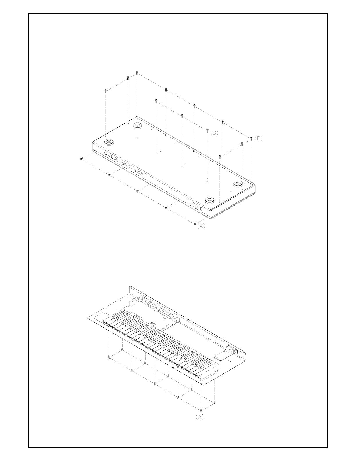
DISASSEMBLY PROCEDURES
1. REMOVAL OF TOP COVER / FRONT BOTTOM PANEL (Fig.1)
(A) TAKE OUT THE 5 PCS SCREWS FROM WHICH
THE REAR PANEL.
(B) TAKE OUT THE 12 PCS SCREWS FROM WHICH
THE BOTTOM PANEL
2. REMOVAL OF KEYBOARD (Fig.2)
(A) TAKE OUT THE 10PCS SCREWS FROM WHICH
THE BOTTOM CHASSIS.
Fig.1
Fig.2
Page 7
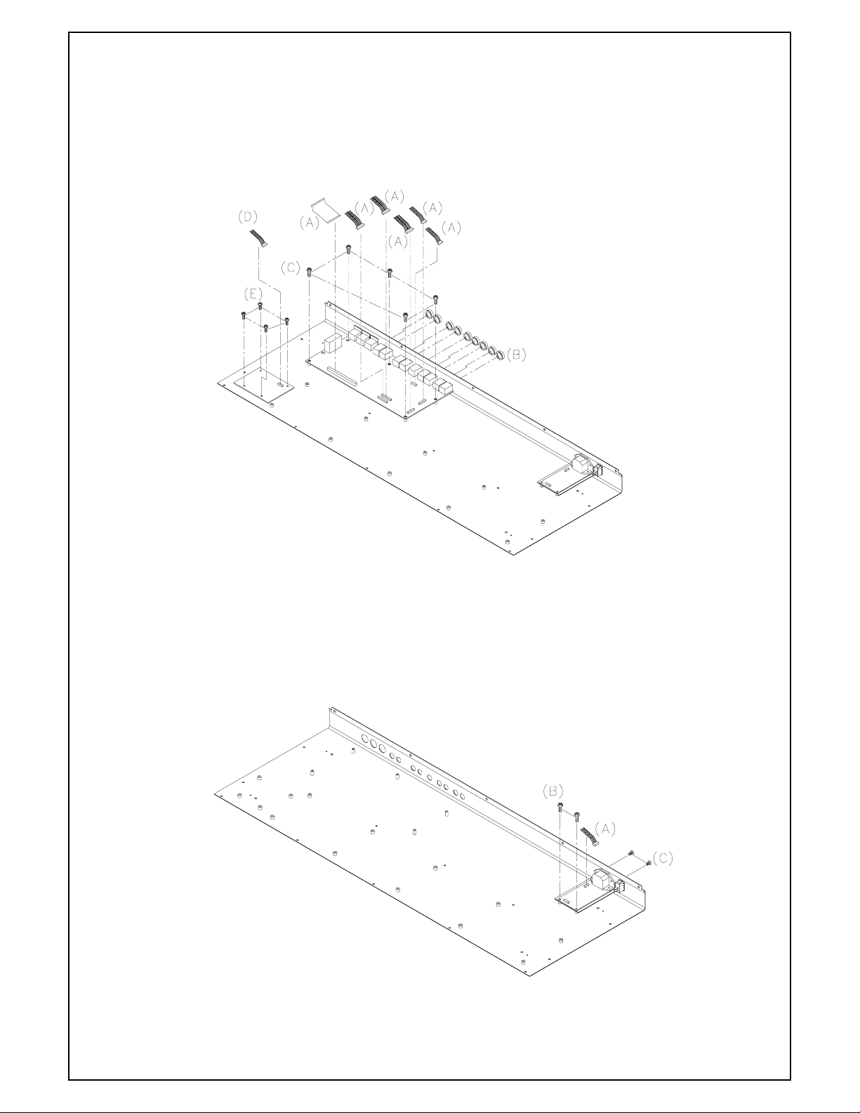
3. REMOVAL OF MAIN P.C.B AND ASSY PCB PITCH/MOD WHEEL LED (Fig.3)
(A) REMOVE 6 PCS OF CABLE CONNECTOR FROM MAIN PCB
(B) REMOVE THE 9 PCS NUT OF 1/4” CONNECTORS FROM REAR PANEL
(C) REMOVE THE 5 PCS SCREW FROM WHICH MAIN PCB
(D) REMOVE 1 PC OF CABLE CONNECTOR FROM PCB PITCH/MOD WHEEL LED
(E) REMOVE 4 PCS OF SCREW FROM PCB PITCH/MOD WHEEL LED
Fig.3
4.REMOVAL ASSY PCB POWER SUPPLY BB01 (Fig.4)
(A) REMOVE 1 PC OF CABLE CONNECTOR FROM PCB TRANSFORMER
(B) REMOVE THE 2 PCS SCREWS FROM PCB TRANSFORMER
(C) REMOVE THE 2 PCS SCREWS FROM REAR PANEL
Fig.4
Page 8
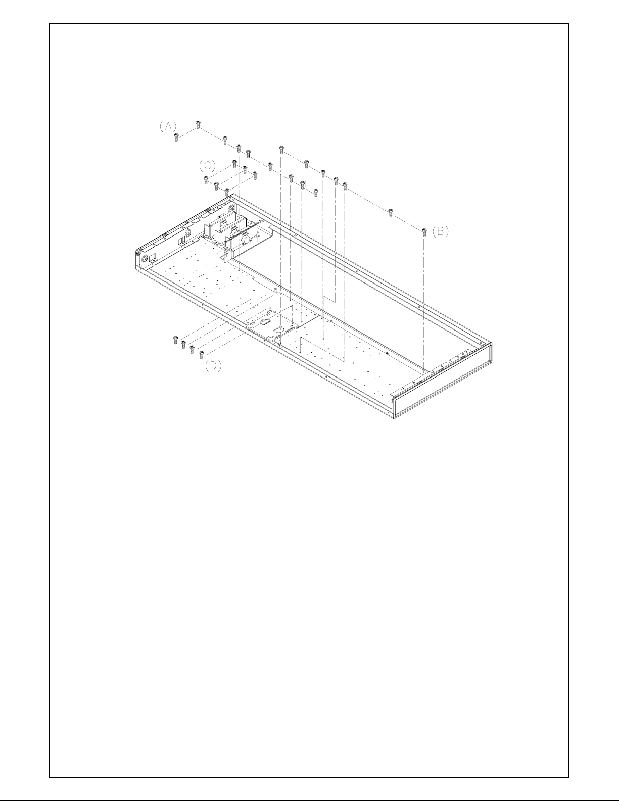
5.REMOVAL ASSY PCB TOP PANEL AND ASSY PITCH AND MOD WHEELS (Fig.5)
(A) REMOVE THE 9 PCS OF SCREWS FROM ASSY PCB TOP PANEL LEFT
(B) REMOVE THE 7 PCS SCREW FROM ASSY PCB TOP PANEL RIGHT
(C) REMOVE THE 6PCS SCREW FROM ASSY PITCH AND MOD WHEELS
(D) REMOVE THE 4PCS SCREW FROM ASSY LCD WITH CABLE
Fig.5
Page 9
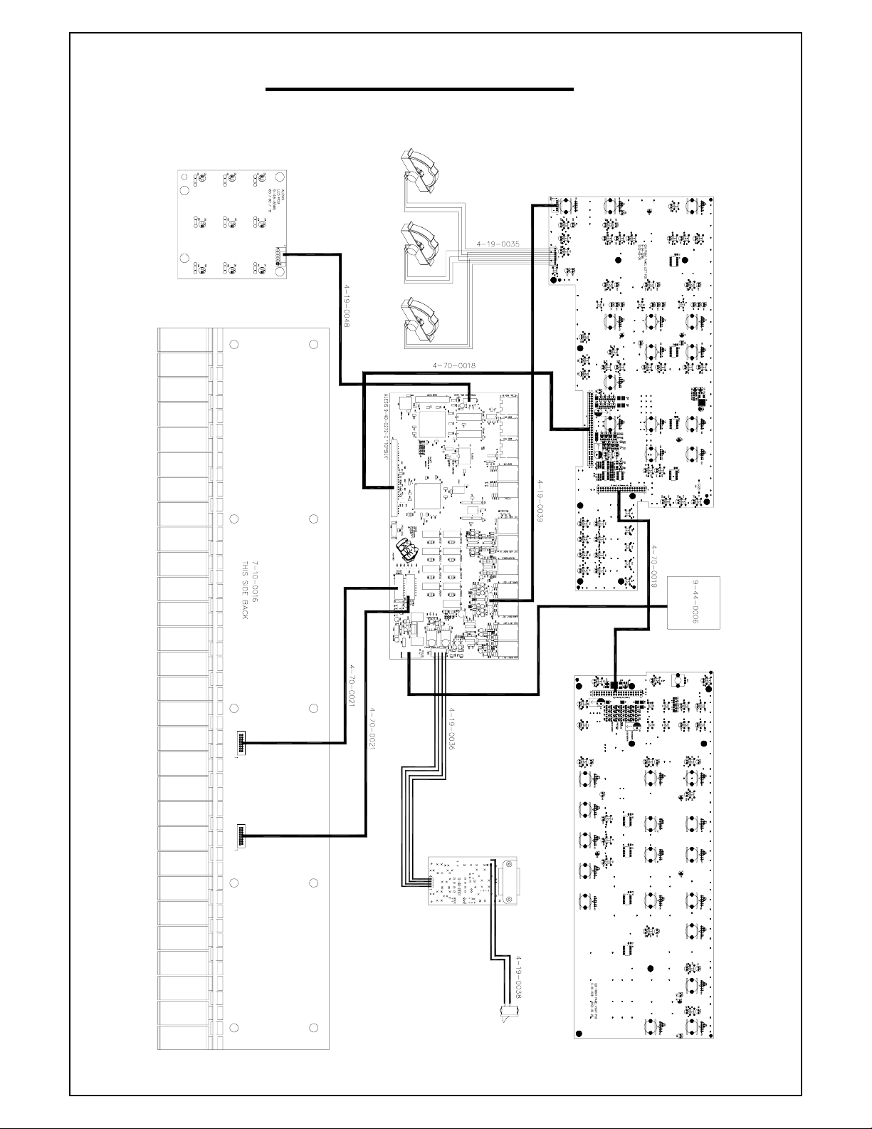
WIRING DIAGRAM
(US/EU/UK/AUS NZ)
Page 10
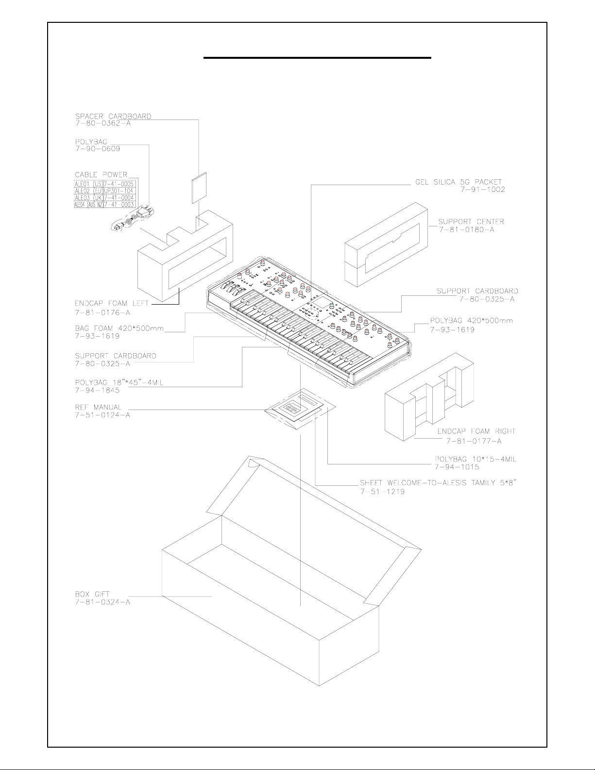
PACKING DIAGRAM
(US/EU/UK/AUS NZ)
Page 11
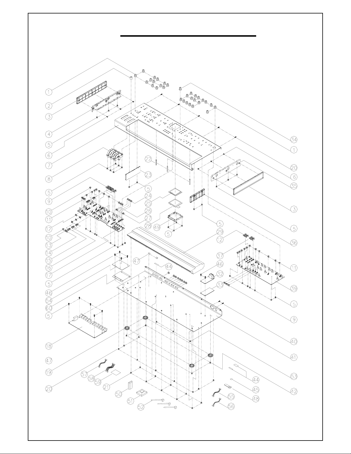
EXPLODE DIAGRAM
(US/EU/UK/AUS NZ)
SEQUENCIAL NO OF EXPLODE DIAGRAM WILL BE MARKED ON REF. COLUMM OF BOM LIST
Page 12

ALESIS
ION (Q01)
BOM
Confidential Alesis Service Manual 8-31-0125-A
Page 13

Ion BOM
LEVEL
1 BAGL-40A CABLE CLIP 1 48
1 5-10-1004 TIE WRAP 4" LOCKING WHITE 3 52
1 LAP67YAH255 STICKER 5
1 5-03-0035 STANDOFF M3 M-F 45.2mm BRASS 3 22
1 9-01-0077-A SUBPANEL ENDCAP LEFT Q01 1 4
1 9-01-0076-A SUBPANEL ENDCAP RIGHT Q01 1 35
1 PQ01ALE01 PACKING ASSEMBLY 1
2 7-80-0362-A SPACER CARDBOARD [CB310N005] Q01 1
2 7-90-0609 POLYBAG 0.007
2 7-93-1619 BAG FOAM 420 X 500mm 2
2 7-51-0124-A REF MANUAL, Q01 1
2 7-51-1219 SHEET WELCOME-TO-ALESIS-FAMILY 5 x 8" 1
2 7-80-0323-A BOX SHIPPING Q01 1
2 7-80-0324-A BOX GIFT Q01 1
2 7-80-0325-A SUPPORT CARDBOARD Q01 2
2 7-81-0176-A ENDCAP FOAM LEFT Q01 1
2 7-81-0177-A ENDCAP FOAM RIGHT Q01 1
2 7-81-0180-A SUPPORT CENTER FOAM Q01 1
2 7-91-1002 GEL SILICA 5G PACKET 1
2 7-94-1015 POLYBAG 10 * 15 - 4 MIL 0.1
2 7-94-1845 POLYBAG 18" X 45" 4MIL 0.1
1 PT0104432 WIRING SEAT 1 51
1 9-15-0305-A ENDCAP CHASSIS LEFT Q01 2 3
1 7-07-0060-A INSULATOR POWER SUPPLY FORMEX W/ ADHESIVE 102 X 72 mm 1 33
1 7-07-0062 INSULATOR SHEET PLASTIC 1 60
1 9-15-0310-A CAP ROUND SWITCH CLEAR Q01 25 11
1 9-15-0311-A CAP ROUND SWITCH BLACK Q01 3 24
1 9-15-0312-A CAP SQUARE SWITCH CLEAR Q01 2 10
1 9-15-0313-A CAP SQUARE SWITCH CLEAR ARROW UP Q01 3 15
1 9-15-0352-A CAP SQUARE SWITCH CLEAR ARROW DOWN Q01 3 16
1 9-15-0351-A CAP SQUARE SWITCH CLEAR ARROW LEFT Q01 1 13
1 9-15-0350-A CAP SQUARE SWITCH CLEAR ARROW RIGHT Q01 1 14
1 9-15-0371-A CAP SQUARE SWITCH BLACK ARROW LEFT FACING Q01 1 26
1 9-15-0370-A CAP SQUARE SWITCH BLACK ARROW RIGHT FACING Q01 1 27
1 9-15-0315-A CAP RECTANGULAR SWITCH CLEAR Q01 18 9
1 9-15-0316-A CAP RECTANGULAR SWITCH BLACK Q01 8 12
1 9-15-0361-A CAP RECTANGULAR SWITCH CLEAR CENTER Q01 4 37
1 5-03-0034 STANDOFF 10 X 10 X 8.8 mm NEOPRENE RUBBER 2 47
1 SC0306PBBI SCREW 6 6
1 SC0306RICI SCREW 6 46
1 SC0406RIBI SCREW 4 42
1 SC3506AIBI SCREW 14 20
1 SC3514PBBI SCREW 10 21
1 4-19-0036-A CABLE SIL 4-PIN CONNECTOR F-F 1 56
1 4-19-0039-A CABLE SIL 6-PIN 2mm F-F 1 57
1 4-19-0048-A CABLE SIL 6-PIN 2mm M - STAKED 1 55
1 4-70-0021-A CABLE DIL RIBBON 16-PIN F-M 2
1 5-00-0020 SCREW 3 53
1 5-00-0106 SCREW 41 5
1 5-00-1020 SCREW 2 40
1 7-10-0116 ASSY KEYBED 49-KEY FATAR TP/7BA 1 29
1 7-41-0005 CABLE POWER UL/CSA (SJT) 1
1 7-50-0179 STICKER BARCODE S/N Q01 1 44
1 7-52-0040-B STICKER ETL/FCC/CE/C-Tick & CAUTION - REV B 1 59
1 7-53-0100 STICKER SYMBOL CAUTION (WHITE-ON-BLACK) 1 45
1 9-01-0056-A TOP PANEL Q01 1 7
1 9-01-0057-A CHASSIS BOTTOM Q01 1 41
1 9-10-0058-A BEZEL LCD CLEAR ACRYLIC Q01 - REV A 1 25
P/N DESCRIPTION QTY REF
Page 14

1 9-15-0076 FOOT ROUND LARGE 4 19
1 9-15-0206 CLIP 150
1 9-15-0302-A KNOB TEXTURED TRANSLUCENT Q01 - REV A 1 34
1 9-15-0303-A KNOB TEXTURED BLACK Q01 - REV A 30 1
1 9-15-0304-A KNOB MAIN VOLUME W/INDICATOR Q01 - REV A 1 2
1 9-15-0307-A ENDCAP KEYBED LEFT Q01 - REV A 1 23
1 9-15-0308-A ENDCAP KEYBED RIGHT Q01 - REV A 1 36
1 9-15-0309-A BRACKET MOUNTING LCD FRONTIGHT 1 49
1 9-44-0006 DISPLAY LCD 160x160 HANTRONIX Y-G LED BACKLIGHT 1 28
1 9-79-BB01 ASSY PCB POWER SUPPLY BB01 1 32
2 7-53-0231-A STICKER FUSE RATING T1AL 250V 1 (C3)
2 9-07-0031 SHIELD EMI/IEC BB 1 (J2)
2 5-04-0062-A INSULATOR 19mm x 20mm PLASTIC 1 (C11)
2 TE617920201 2P AC CONNECTOR 1 (J3)
2 0-00-0221 RES 220 OHM 1/8W 5% 1 R1
2 0-00-0689 RES 6.8 OHM 1/8W 5% 1 R2
2 0-01-2213 RES 221K OHM 1/8W 1% 2 R3,4
2 0-05-1104 RES 100K OHM 1W 5% 1 R5
2 1-02-0104 CAP 0.1uF CERDISC 10% .30"DIA. 1 C1
2 1-02-5103 CAP 0.01uF CERDISC 20% 500V 5x5x2mm 1 C6
2 1-08-0474 CAP 47uF ELEC 16V 2x5x11mm 1 C5
2 1-08-1000 CAP 1000uF ELEC 20% 16V 5x10.2x20mm 2 C7,9
2 1-09-0221 CAP 220uF ELEC 25V 3.5x8x12.5mm 4 C2,4,10,12
2 1-13-4472 CAP 47uF ELEC 400V 7.5x18x25mm 1 C11
2 1-14-0104 CAP 0.1uF X2-CAP +/-20% 250VAC 15x17.5x5x10.5mm 2 C3,8
2 1-15-0103 CAP 0.01uF Y-CAP 250 VAC 15.2X18.5X5.2X10.5mm 2 C14,15
2 1-15-2102 CAP 1000pF Y-CAP 250VAC 5x6.5x4.5mm 1 C13
2 2-01-0120 DIODE POWER ULTRA-FAST MUR120 1A 200V 2 D2,6
2 2-01-5822 DIODE SCHOTTKY 1N5822 3A 40V 1 D3
2 2-02-0600 DIODE POWER ULTRAFAST MUR160 600V 1A 1 D4
2 2-02-4751 DIODE ZENER 1N4751 30V 1W DO-41 1 D5
2 2-03-0105 RECTIFIER BRIDGE DB105 1A 600V 1 D7
2 2-05-0223 TRANS OFF-LINE PWM SWITCH 50W TO-223 1 Q2
2 2-24-8104 IC OPTO-ISOLATOR TCDT1124 6-PIN 1 Q1
2 2-99-0021 DIODE BAV21 1 D1
2 4-09-0010 CON PWR IEC 10A 250V PCB-MOUNT (TOP GND LUG) 1 J2
2 4-15-0204 HEADER SIL 4-PIN 1 J1
2 5-05-1001 CLIP FUSE HOLDER (5 x 12mm) 2 F1
2 7-04-0012 FUSE 2A 250V 5X20mm F UL-LISTED 1 (F1)
2 7-20-0064 INDUCTOR 100uH 0.58A 5x8.5x11.5mm 20% 1 L1,4
2 7-20-0065 INDUCTOR 22uH 1.29A 5x8.5x11.5mm 20% 1 L2
2 7-30-0025 CHOKE COMMON MODE 10mH 3.5 OHMS 1 L3
2 7-40-0038 TRANSFORMER HI-FREQ SWITCHING FLYBACK EI25-CORE BB 1 T1
2 9-40-BB01-E PCB POWER SUPPLY BB01- REV E 1
1 9-79-0272-C ASSY PCB MAIN Q01 Rev C 1 18
2 CS103K5005X7R CERAMIC 0.01UF 74
2 CS104K2505X7R CERAMIC 0.1UF 17
C2~14,18,21,73~92,94~109,114~116,118,12
1,122,127 ,128,130~141,143,144,150
C1,24,29~31,35,40,58,70,71,93,110,111,112,
123~125
2 5-04-0061-A INSULATOR 4.1mm x 18mm PLASTIC 1 (J3)
2 RS10118J05 RESISTOR 100O (SMD) 6 R96,97,100,101,105,106
2 RS10218J05 RESISTOR 1K (SMD) 27
2 RS10318J05 RESISTOR 10K (SMD) 18
R10,11,15,27,34,39,40~42,44~46,50,51,63,6
5,74,76,77,86,108,113,114,120~122,140
R4,7~9,13,14,18,31~33,52,90,91,104,112,13
1,133,139
2 RS10418J05 RESISTOR 100K (SMD) 13 R12,16,17,23~26,28~30,43,61,62
2 RS18218J05 RESISTOR 1.8K (SMD) 4 R19,20,36,37
2 RS20318J05 RESISTOR 20K (SMD) 8 R53,54,58,59,70,78,79,84
Page 15

2 RS24218J05 RESISTOR 2.4K (SMD) 1 R136
2 RS30218J05 RESISTOR 3K (SMD) 11 R55~57,60,64,67,69,75,80,82,85
2 R10218 RESISTOR 1KO 1 R141
2 TE10200601 6P CONNECTOR 2 (J2,12)
2 5-01-0029 WASHER 1 (U37)
2 WS663309IC WASHER 3 (U31,32,37)
2 0-05-0100 RES 10 OHM 1/2W 5% 1 R138
2 0-15-0912 RES 9.1K OHM 1/10W 5% 0805 8 R48,49,66,68,71,72,81,83
2 0-16-2210 RES 221 OHM 1/10W 1% 0805 16
R1,5,21,22,35,38,47,73,87,92,98,99,102,103,
135,137
2 0-16-3650 RES 365 OHM 1/10W 1% 0805 1 R134
2 0-17-0102 RES CHIP ARRAY 4 x 1K OHM 1/16W 5% ISOLATED c-c=0.8mm 5 R2,109,111,115,117
2 0-17-0103 RES CHIP ARRAY 4 x 10K OHM 1/16W 5% ISOLATED c-c=0.8mm 7 R88,89,107,110,124,126,132
2 0-17-0221 RES CHIP ARRAY 4 X 220 OHM 1/16W 5% ISOLATED c-c=0.8mm 10 R6,116,118,119,123,125,127~130
2 0-17-0470 RES CHIP ARRAY 4 X 47 OHM 1/16W 5% ISOLATED c-c=0.8mm 3 R93-95
2 1-08-0222 CAP 22uF ELEC 20% 16V 1.5x4x7mm 25
C19,20,25,28,32,36,37,41~44,54~57,67~69,1
17,119,120,126,129,145,146
2 1-08-0223 CAP 220 uF 16V ELEC 1 C113
2 1-11-0225 CAP 2.2uF ELEC 50V 5 C72,142,147~149
2 1-55-0561 CAP 560pF NPO 0805 20
C15~17,22,23,26,27,33,34,38,39,49,50~53,5
9~61,64
2 1-56-0151 CAP 150pF NPO 0805 8 C45~48,62,63,65,66
2 2-05-0111 TRN TRANSISTOR JFET J111 2 Q6,7
2 2-11-1317 REG LM317 POS ADJUSTABLE REGULATOR 3 U32,37,38
2 2-11-2940 REG LM2940CT-5.0V 1 U31
2 2-13-7812 REG LM78L12 +12V REGULATOR 1 U35
2 2-13-7912 REG LM79L12 -12V REGULATOR 1 U34
2 2-24-0138 IC 6N138 OPTO ISOLATOR 1 U1
2 2-50-4148 DIODE 1 D16
2 2-50-4149 DIODE SIGNAL 1N4148 SMD SOT-23 13 D1~8,11~15
2 2-51-0140 DIODE SCHOTTKY MBRS140T3 1A 40V SMD 2 D9,10
2 2-51-4401 TRANS 2N4401 NPN 5 Q1,3,4,11,12
2 2-51-4403 TRANS 2N4403 PNP 6 Q2,5,8~10,13
2 2-62-0004 IC 74AHC04 HEX INVERTERS 1 U15
2 2-62-0574 IC 74AHC574 OCTAL D FF W/TRI-STATE OUTS SMI 1 U18
2 2-62-1014 IC 74AHCT14 HEX SCHMITT-TRIGGER INVERTER 14-PIN SOP 1 U2
2 2-64-5161 IC 74LVC161 SYNC 4-BIT BINARY COUNTER SOP-16 4 U3,5,17,20
2 2-66-6256 IC DRAM 256K x 16 35nS 40-PIN SOJ 2 U11,12
2 2-67-6256 IC SRAM 32K x 8 15ns 3.3V TSOP-28 1 U4
2 2-69-2416 IC EEPROM SERIAL 16K SOIC-8 1 U39
2 2-69-2880 IC FLASH-ROM 512Kx16 110nS 48-PIN TSOP 1 U14
2 2-70-5206 IC MPU MCF5206E 54MHz 160-PIN QFP 1 U13
2 2-71-0084 IC TL084 QUAD OPAMP SOP-14 3 U6,9,10
2 2-71-3079 IC MC33079 4-OPAMP SOP-14 1 U8
2 2-75-1101 IC CONVERTER ADC 24-BIT AL1101 SOP-16 1 U7
2 2-75-1201 IC CONVERTER DAC 24-BIT AL1201 SOP-16 2 U30,33
2 2-77-0096 IC DSP 1KM/AL3101 28-PIN SOIC 9 U21~ 29
2 2-79-1818 IC CONTROLLER RESET W/OVERRIDE DS1818-10TR +3.3V SOT-23 1 U16
2 2-80-0007 IC FPGA EP1K30QC208-2 208-PIN PQFP 1 U19
2 4-00-0002 JACK DIN 5-PIN MIDI PCB MOUNT 180 W/SHIELD 3 J1,3,4
2 4-02-0007 JACK 1/4 STEREO 7-PIN FEM MINI W/GRND LUG STRAIGHT 9 J5~11,13,14
2 4-14-0116 HEADER DIL 16-PIN 0.1 SHRD 2 J19,20
2 4-14-2601 HEADER DIL 26-PIN 0.1" MALE 1 J15
2 4-14-6000 HEADER DIL 60-PIN 0.1" MALE 1 J17
2 4-15-0010 HEADER DIL 10-PIN 0.1 1 J18
2 4-15-0204 HEADER SIL 4-PIN 3.96mm MALE EXT-LOCKING 1 J16
2 4-15-1800 HEADER SIL 18-PIN 1mm FEM FFC 1 J21
2 5-00-0006 SCREW 4-40X1/2" 1 (U37)
2 5-00-0106 SCREW 4-40X1/2" 2 (U31,32)
2 5-02-0009 HEATSINK 2 (U31,32)
Page 16

2 5-02-4402 NUT 1 (U37)
T
2 6-02-0050 SWITCH TACT TL1105T 1 S1
2 7-01-0035 OSCILLATOR 54MHz 3.3V 8-PIN DIP 1 U36
2 9-03-1132 HEATSINK 1
2 9-40-0272-C PCB MAIN Q01 Rev C 1
1 9-79-0280-A ASSY PCB TOP PANEL LEFT Q01 Rev A 1 17
2 1-56-0104 CERAMIC 0.1UF 21 C2~6,8,9,14~22,24~28
2 PT0704402 LED HOLDER (7.5mm) 21
(D12~15,17~19,21,24,25,29,31,37,40,47~49,
55,59,62)
2 0-15-0103 RESISTOR 10K (SMD) 1 R8
2 0-15-0104 RESISTOR 100K (SMD) 8 R27~34
2 0-15-0151 RESISTOR 150O (SMD) 1 R35
2 0-15-0471 RESISTOR 470O (SMD) 1 R36
2 TE10200601 6P CONNECTOR 1 J5
2 TE612000901 9P CONNECTOR 1 J3
2 0-09-0036 POT 5KB DUAL 360 DEG TURN 13 R12~24
2 0-09-0041 POT 10KA DUAL 1 R11
2 0-16-2002 RES 20.0K OHM 1/10W 1% 0805 1 R7
2 0-17-0101 RES CHIP ARRAY 4 x 100 OHM 1/16W 5% ISOLATED c-c=0.8mm 4 R2,3,4,6
2 0-17-0103 RES CHIP ARRAY 4 x 10K OHM 1/16W 5% ISOLATED c-c=0.8mm 2 R25,26
2 0-17-0270 RES CHIP ARRAY 4 X 27 OHM 1/16W 5% ISOLATED c-c=0.8mm SMD 2 R1,5
2 1-08-0222 CAP 22uF ELEC 20% 16V 1.5x4x7mm 5 C1,11,12,13,29
2 1-08-0223 CAP 220 uF 16V ELEC 2 C10,23
2 1-56-0102 CAP 1000PF 5% 100V NPO 0805 1 C7
2 2-51-4401 TRANS NPN 2N4401 40V 1A SOT-23 17 Q1,5,6,12~15,17,19~27
2 2-51-4403 TRANS PNP 2N4403 40V 800mA SOT-23 10 Q2~4,7~11,16,18
2 2-72-0339 IC LM339 QUAD COMPARATOR SMD 3 U5,6,7
2 2-72-4051 IC CD4051 SINGLE 8-CHAN MUX 16-PIN SOIC 4 U1,2,3,4
2 3-02-0028 LED RED T1 CLEAR (NON-DIFFUSED) 4204-10IT 49
D9~21,23~26,29~35,37~42,47~56,58~62,64~
67
2 3-02-0029 LED GRN T1 CLEAR (NON-DIFFUSED) 4204-10GT 10 D22,27,28,36,43,44,45.46,57,63
2 4-70-0018-A CABLE DIL RIBBON 60-PIN F-F 1 J2
2 4-70-0019-A CABLE DIL RIBBON 40-PIN F-F 1 J4
2 6-02-0050 SWITCH TACT TL1105T 47 S1~5,7-48
2 9-40-0280-A PCB TOP PANEL LEFT Q01 Rev A 1
1 9-79-0281-C ASSY PCB TOP PANEL RIGHT Q01 Rev C 1 39
2 1-56-0104 CERAMIC 0.1UF 22 C2~5,11~28
2 PT0704402 LED HOLDER (7.5mm) 9 (D3,5.14,15,20,28,31,33,34)
2 0-15-0101 RESISTOR 100O (SMD) 2 R28,29
2 0-15-0102 RESISTOR 1K (SMD) 3 R23,24,25
2 0-09-0036 POT 5KB DUAL 360 DEG TURN 17 R5~21
2 0-15-0100 RES 10 OHM 1/10W 5% 0805 2 R26,27
2 0-15-0101 RES 100 OHM 1/10W 5% 0805 3 R1,2,3
2 0-17-0103 RES CHIP ARRAY 4 x 10K OHM 1/16W 5% ISOLATED c-c=0.8mm 1 R22
2 0-17-0270 RES CHIP ARRAY 4 X 27 OHM 1/16W 5% ISOLATED c-c=0.8mm SMD 1 R4
2 1-08-0222 CAP 22uF ELEC 20% 16V 1.5x4x7mm 4 C1,7,8,9
2 1-08-0223 CAP 220 uF 16V ELEC 2 C6,10
2 2-51-4401 TRANS NPN 2N4401 40V 1A SOT-23 18 Q5~22
2 2-51-4403 TRANS PNP 2N4403 40V 800mA SOT-23 6 Q1~4,23,24
2 2-72-4051 IC CD4051 SINGLE 8-CHAN MUX 16-PIN SOIC 4 U1~4
2 3-02-0028 LED RED T1 CLEAR (NON-DIFFUSED) 4204-10IT 14 D3,5,14,15,17,20~23,256,28,31,33,34
2 3-02-0029 LED GRN T1 CLEAR (NON-DIFFUSED) 4204-10GT 11 D1,2,16,18,24,26,29,30,32,35,36
2 3-02-0030 LED YEL T1 CLEAR (NON-DIFFUSED) 4204-10YT 2 D4,27
2 3-02-0042 LED BLUE T1 DIFFUSED 1 D19
2 4-14-0040 HEADER DIL 40-PIN 0.1" SHRD 1 J1
2 6-00-0010 ENCODER 24-DETENT 12mm VERT-MT 14mm FLAT-THREADED-SHAF
1 ENC1
2 6-02-0050 SWITCH TACT TL1105T 23 21~23
2 9-40-0281-C PCB, TOP PANEL RIGHT Q01 Rev C 1
Page 17

1 9-96-0082 ASSY PITCH AND MOD WHEELS Q01 1 8
2 9-03-0145-A BRACKET PITCH/MOD WHEEL 3
2 WS1306505 WASHER 1
2 0-09-0037 POT 5KB SINGLE CONTROL EYELET 18MM SHAFT 3
2 4-19-0035 CABLE SIL 6-PIN PITCH/MOD WHEEL Q01 1
2 7-13-0080 TUBING HEATSHRINK 1/16" DIA x 5/8" 300V 80c 2
2 9-06-0018 SPRING, MOD WHEEL 2
2 9-06-0030 SPRING PITCH WHEEL 1
2 9-15-0301-A WHEEL PITCH & MOD Q01 - REV A 3
1 9-96-0096 ASSY CABLE AC POWER SWITCH Q01 1
2 7-13-0001 TUBING HEATSHRINK 5mm DIA x 15mm 2
2 4-19-0038-B CABLE SIL 2-PIN 7.92mm HEADER-F 1
2 6-02-0036 POWER SWITCH 1
1 9-96-0305-A ASSY PCB PITCH/MOD WHEEL LED 1 54
2 R47016 RESISTOR 1
2 TE10200602 HEADER 1
2 3-02-0028 LED RED T1 CLEAR (NON-DIFFUSED) 4204-10IT 9
2 9-40-0305-A PCB PITCH/MOD WHEEL LED - REV A 1
Page 18

Q01 QC Test Procedures
Items required for test (one each unless otherwise specified):
• Q01 unit with current OS
• IEC power cable
• MIDI cable
• Sustain pedal
• Pair of headphones
• AP Computer w/ cables
Setup and Calibration:
1) Connect IEC power cable from Q01 to power outlet.
2) Connect the MIDI cable from Q01 MIDI OUT to Q01 MIDI IN.
3) Plug sustain pedal into the expression pedal input jack on the Q01.
4) Plug the headphones into the headphone output jack of the Q01 (marked with
a headphones symbol). Turn Master Volume knob (red knob) completely
CCW.
5) Power up Q01 while holding down PAGE < and > PAGE buttons. This brings
the Q01 into diagnostic mode. Verify that the text “ diagnostic” appears at the
very top of the LCD.
6) Using the > PAGE button, go to page 3 of the diagnostics (text at top of LCD
should read “ EXT IN AUDIO TEST” and text at bottom of LCD should read “ 3
of 3” ).
7) Press the soft button beneath “ whl cali p hi” text at the bottom of the LCD (text
at top of LCD should now read “ WHEEL CALIBRATION” and the text “ whl cali
p hi” should now be highlighted).
Pitch Wheel Calibration
8) Verify that there is an arrow pointing up towards a number, in a box labeled
“ p.” Move pitch wheel “ p1” to its top-most position and press the “compare”
button. This calibrates the top range of the pitch wheel.
9) Turn the encoder one click CCW. The arrow in box “ p” should now be pointing
down towards another number. Move pitch wheel “ p1” to its bottom-most
position and press compare. This calibrates the bottom range of the pitch
wheel.
Mod Wheel 1 Calibration
10) Turn the encoder one click CCW. The arrow should now be pointing up in a
box labeled “ m1.” Move mod wheel “ m1” to its top-most position and press
“ compare.”
Page 19

11) Turn the encoder one click CCW. The arrow should now be pointing down in
box “ m1.” Move mod wheel “ m1” to its bottom-most position and press
“ compare.”
Mod Wheel 2 Calibration
12) Turn the encoder one click CCW. The arrow should now be pointing up in a
box labeled “ m2.” Move mod wheel “ m2” to its top-most position and press
“ compare.”
13) Turn the encoder one click CCW. The arrow should now be pointing down in
box “ m2.” Move mod wheel “ m2” to its bottom-most position and press
“ compare.”
Expression Pedal Calibration
14) Verify that the sustain pedal is plugged into the expression pedal input
of the Q01, not the sustain pedal input.
15) Turn the encoder one click CCW. The arrow should now be pointing up in a
box labeled “ exp.” Press the “ compare” button.
16) Turn the encoder one click CCW. The arrow should now be pointing down in
box “ exp.” Press the sustain pedal and press the “ compare” button.
This concludes calibration.
17) Power cycle the Q01 while holding down PAGE < and > PAGE buttons.
Verify that the text “ diagnostic” appears at the very top of the LCD.
18) Plug the sustain pedal back into the sustain pedal input of the Q01.
Procedures:
1) Visual Inspection
a) Inspect the front panel for dents and scratches.
b) Make sure that the end caps are properly seated into the chassis. Verify
that they also don’ t have any dents any scratches.
c) Verify that all the jacks on the rear of the Q01 have nuts installed.
2) LED Test
a) Verify that the LCD displays the texts “ LED TEST” and “ all LEDs are on.”
b) Verify that all the LEDs on the Q01 are indeed on and that the brightness
between LEDs of the same type/color is consistent.
c) Turn the encoder one click CCW (translucent white knob to the right of the
LCD). Verify that the LCD displays the text “ all LEDs are off” and verify
that all LEDs turn off.
d) For all the exposed LEDs (the ones protruding through the front panel),
verify that they do not have any visible scratches.
Page 20

3) Button/Sustain Pedal Test
a) Press the soft button beneath the LCD text “ button sust pdl.” Verify that
the LCD text “ button sust pdl” is now highlighted, and that the texts
“ BTN/SUST PDL TEST” and “ press any button” are now displayed in the
middle of the LCD.
b) Test all the buttons on the Q01 front panel EXCEPT for the following:
PAGE <, > PAGE, and the three soft buttons beneath the LCD (between
PAGE < and > PAGE buttons).
c) When a button is pressed down, verify that the name of that button is
displayed on the LCD, and that the LCD indicates the button is pressed
down with the text “ button DOWN.”
d) When the button is released, verify that the LCD indicates the button has
been released with the text “ button UP.”
e) As each button is pressed, make sure that the silk screen on that button is
not scratched or misaligned. Also verify that all the buttons have a
consistent feel, and that they should generate one “ click” when pressed.
f) Press on the sustain pedal. Verify that the LCD displays “ sust pedal button
DOWN.”
g) Release the sustain pedal. Verify that the LCD displays “ sust pedal button
UP.”
4) Pot/Expression Pedal/Wheel Test
a) Press the soft button beneath the LCD text “ pot exp pdl.” Verify that the
LCD text “ pot exp pdl” is now highlighted, and that the texts “ POT/EXP
PDL TEST” and “ turn any pot” are displayed in the middle of the LCD.
b) Test all the pots on the Q01 front panel except the Master Volume.
c) When a pot is turned, verify that the pot’ s name is displayed on the LCD
and pot indicator moves smoothly. NOTE: If the pot is turned CW, the pot
indicator will move from left to right, and the percent value will increase.
Conversely, if the pot is turned CCW, the pot indicator will move from right
to left, and the percent value will decrease. Also, some pots are more
sensitive than others. This is normal and should not be considered a
failure (i.e. the FILTER 1 FREQ pot is more sensitive than the FILTER 1
RES pot).
d) Also verify that there are no bumps or rough spots felt on the pot knob as
it is rotated CW or CCW.
e) Plug the sustain pedal into the expression pedal input jack of the Q01.
f) Press on the sustain pedal and verify that the LCD displays the text “ exp
pedal” and the value “ 0” .
g) Release the sustain pedal and verify that the LCD now displays a value of
“16383.”
h) Move pitch wheel P up and verify that the LCD shows the text “ pitch
wheel” and a value of 16383.
i) Move pitch wheel P down and verify that the LCD shows a value of 0.
Page 21

j) Move modulation wheel M1 up and verify that the LCD shows the text
“ mod 1 wheel” and a value of 16383.
k) Move modulation wheel M1 down and verify that the LCD shows a value
of 0.
l) Repeat steps j) and k) with modulation wheel M2.
m) Verify that the “ref” value (displayed above the pot or wheel name) is
between 2500 and 3200 (typically it should be around 2800). Note that this
value will change slightly as the pots and wheels are tested. This is
normal, but the variation should be no more than +/-1%.
5) Keyboard Test
a) Press the PAGE > button once. Verify that the LCD text “ keyboard” is now
highlighted (at the bottom of the LCD), and that the texts “ KEYBOARD
TEST” and “ press any key” are displayed in the middle of the LCD.
b) Test every key on the Q01. Verify that the leftmost key has a note number
of 36, and that the rightmost key has a note number of 84 (the key’ s note
number is displayed on the LCD when that key is pressed/released).
c) As each key is pressed, make sure that the key movement and feel is
consistent with all the other keys. Inspect the keys as well for scratches
and dents.
d) When a key is pressed, verify that the note number of that key is displayed
on the LCD, and that the LCD indicates the key is pressed with the text
“ key DOWN.”
e) When the key is released, verify that the LCD indicates the key has been
released with the text “ key UP.”
6) Encoder Test
a) Press the soft button beneath the LCD text “ encoder.” Verify that the LCD
text “ encoder” is now highlighted, and that the texts “ ENCODER TEST”
and “ turn the encoder” are displayed in the middle of the LCD.
b) Turn the encoder CW. Verify that the LCD displays a positive number that
increments as the encoder is turned, and that the arrow is pointing to the
right.
c) Turn the encoder CCW. Verify that the LCD now displays a negative
number that decrements as the encoder is turned, and that the arrow is
now pointing to the left.
7) MIDI Test
a) Press the soft button beneath the LCD text “ midi.” The LCD text “ midi”
should now be highlighted, and the texts “ MIDI LOOP TEST” and “ press
[compare]” should be displayed in the middle of the LCD.
b) Press the COMPARE button (located below the encoder, to the right of
the LCD). Verify that the LCD displays “ passed.”
Page 22

8) Audio Output Test
a) While listening to the headphones, press a key and turn the Master
Volume knob clockwise until the tone is at a comfortable listening level
(this verifies that the Master Volume pot is functional). Verify that both the
left and right sides of the headphones produce a tone.
b) Plug the headphones into the Q01 main output left jack. Verify that when a
key a pressed, a tone is heard on one side (left side) of the headphones.
NOTE: the Master Volume knob may require adjustment in order to hear
this tone more easily.
c) Repeat step b) for the Q01 main output right jack, and the Q01 aux output
left and right jacks. Note that for the aux outputs, the Master Volume
knob has no effect.
9) Voice DSP Test
a) Plug the headphones into the Q01 headphone output jack (Master
Volume knob may require readjustment to bring headphone output to a
comfortable listening level).
b) Press and hold down a key (do not release). A single tone should be
heard from the headphones.
c) Press and hold a second key (do not release the first key) and verify that a
second tone is heard together with the first one.
d) Press and hold a third key (do not release the first and second key) and
verify that a second tone is heard together with the first and second ones.
e) Repeat step d) five more times, so that a total of eight notes are playing
simultaneously, each time verifying that the new note is heard along with
the existing notes that are already playing.
10) External Audio Input Test
a) Press the PAGE > button once. Verify that the LCD text “ ext in” is now
highlighted (at the bottom of the LCD), and that the text “ EXT IN AUDIO
TEST” is displayed in the middle of the LCD (there should also be a
diagram of the audio path).
b) Connect the AP generator output to the Q01 external input left.
c) Set the AP generator output to produce a 2Vp, 1KHz sinewave and turn
on the output.
d) Verify that there is a tone from the left side of the headphones
e) Connect the AP generator output to the Q01 external input right and verify
that there is a tone from the right side of the headphones.
11) AP Test
a) Unplug the headphones from the Q01 headphones jack.
b) Turn the Master Volume knob completely clockwise.
c) Connect the AP generator outputs A and B to the Q01 external in left and
right, respectively.
Page 23

d) Connect the Q01 main output left and right to the AP analyzer inputs A
and B, respectively.
e) Run the AP tests (SNR, THD+N, and frequency response).
f) Repeat steps d) and e) for the Q01 aux outputs left and right.
12) Serial EEPROM Test
a) Press the soft button beneath the LCD text “ eeprom.” The LCD text
“ eeprom” should now be highlighted, and the texts “ EEPROM TEST” and
“ press [compare] to start EEPROM test” should be displayed in the middle
of the LCD.
b) Press the COMPARE button to test the serial EEPROM. If the EEPROM
is functional, the LCD will display “ testing” briefly, followed by “ passed.” If
the EEPROM is not functioning properly, the LCD will display “ testing” for
several seconds, followed by “ failed.”
END OF QC TEST PROCEDURES
Page 24

ALESIS
ION (Q01)
SCHEMATIC
AND
PCB
FILES
Confidential Alesis Service Manual 8-31-0125-A
Page 25

Page 26

Page 27

Page 28

Page 29

Page 30

Page 31

Page 32

Page 33

Page 34

Page 35

Page 36

Page 37

Page 38

Page 39

Page 40

Page 41

Page 42

Page 43

Page 44

Page 45

Page 46

 Loading...