

Alesis ION Owner’s Manual
8-Voice Analog Modeling Synthesizer
Quick Start Owner’s Manual
(ENGLISH)
BOX CONTENTS
• SYNTHESIZER
• POWER CABLE
Manual de inicio rápido para el usuario
(ESPAÑOL)
CONTENIDO DE LA CAJA
• SINTETIZADOR
• CABLE DE ALIMENTACIÓN
Schnellbedienungsanleitung
(DEUTSCH)
INHALT DER VERPACKUNG
• SYNTHESIZER
Manuel d’utilisation du propriétaire
(FRANÇAIS)
CONTENU DE LA BOÎTE
• SYNTHÉTISEUR
• CÂBLE D’ALIMENTATION
Manuale rapido di utilizzazione
(ITALIANO)
CONTENUTO DELLA CONFEZIONE
• SINTETIZZATORE
• CAVO DI ALIMENTAZIONE

This page intentionally left blank.
ION QUICK START OWNERS MANUAL
(ENGLISH)
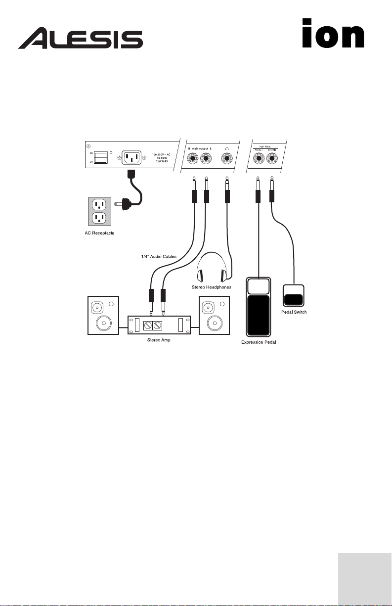
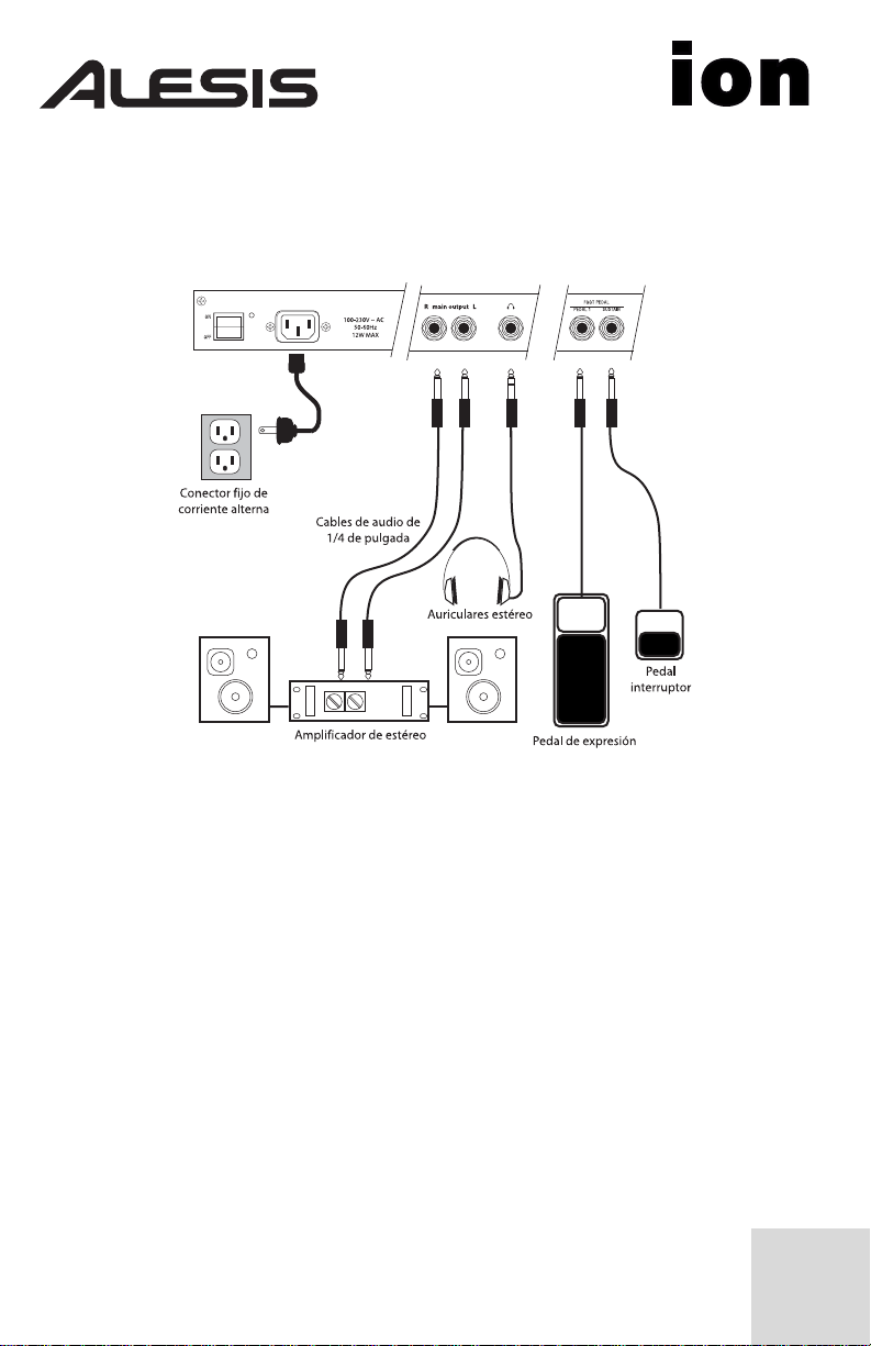
Connection Diagram
Connecting AC Power
Before making any power connections, make sure the Ion’s power switch
is turned off.
1. Plug the female end of the power cable into the Ion’s
power socket.
2. Plug the male (plug) end into a properly grounded power outlet.
Making Audio Connections
• Stereo. Connect two cables from the Ion’s left and right outputs to
• Headphones. Plug a set of headphones into the headphone jack on
two inputs of an amp or mixer.
the rear panel.
1
Connecting the Foot Pedals
• (sust pedal) is designed to work with any standard momentary
footswitch. The Ion will calibrate itself to a normally open or normally
closed pedal if the pedal is plugged in when the Ion is powered on.
• (exp pedal) is designed to work with a Roland EV-5 pedal or
equivalent.
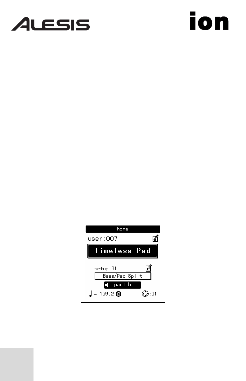
The display
The Liquid Crystal Display (LCD) is at the center of the Ion in more ways
than one. Depending on the button or knob you’ve activated, it may
show the program name, which Programs are used in a Setup, the values
of the parameters being edited, or even a graphic representation of a
waveform or an envelope.
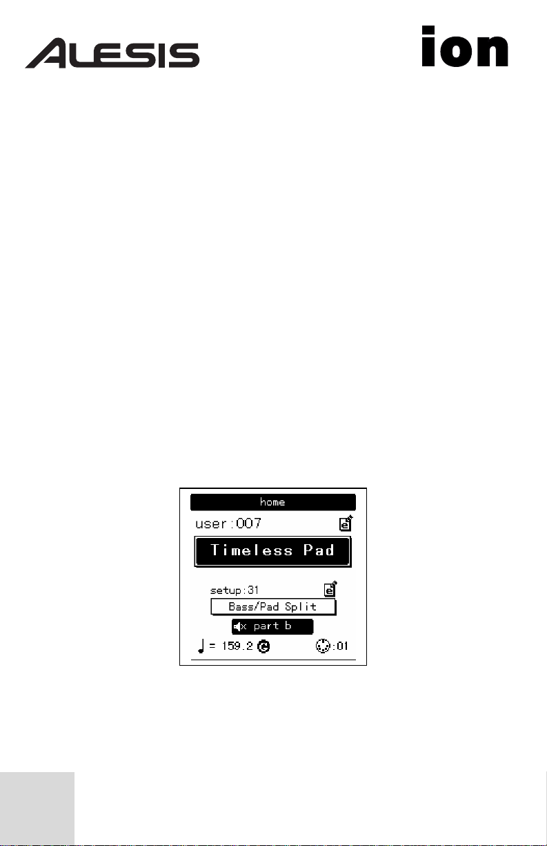
The Home page
This is the screen that shows you the most different kinds of information
all at once. If you’re not already there, press the [home] button and
you’ll see something like this:
Here’s what each area of the Home screen means:
• The darkened bar at the top of the screen shows you the name of
the section being displayed. In this case, it reads home.
• Immediately below that are the bank and program number.
2

• Roughly in the middle you see the program name of the active
Part.
• The fourth line from the bottom shows the Setup number.
• Below that, the outlined rectangle shows the current Setup name.
• The “e box” icons to the right of the Program and Setup numbers
indicate that the Program and Setup have been edited, respectively.
• The filled rectangle on the second line from the bottom shows
which of the four Parts has been selected with the [panel active]
buttons.
Note: the icon on the inside left of this box indicates that the current
Part has been muted.
• The “quarter note” icon, the “equal to” sign (=) and the numbers to
its right tell you what the tempo setting is for the Setup.
• The “G” to the right of the tempo value indicates the setting of the
Global mode parameter tempo source. If the “G” is there, that
means the tempo source parameter is set to global. This causes the
tempo to remain the same when you recall a new Setup or change
Programs. If the “G” is not there, the tempo source parameter is set
to program. In this case, the tempo value can change from one
Setup to the next, or when you call up another program in Part A.
• The “MIDI connector” icon and the number to its right indicate the
MIDI Channel of the currently selected Part.
The Edit pages
Any time a knob is moved or a button is pressed, the Ion enters Edit
mode and displays a screen with parameters related to that knob or
button. The appearances of the pages can vary quite a bit, but there are
some things they have in common:
There can be up to three parameters displayed on any page. If the
desired parameter does not have a front panel knob, select it using a Soft
button and turn the data knob to edit the value.
3
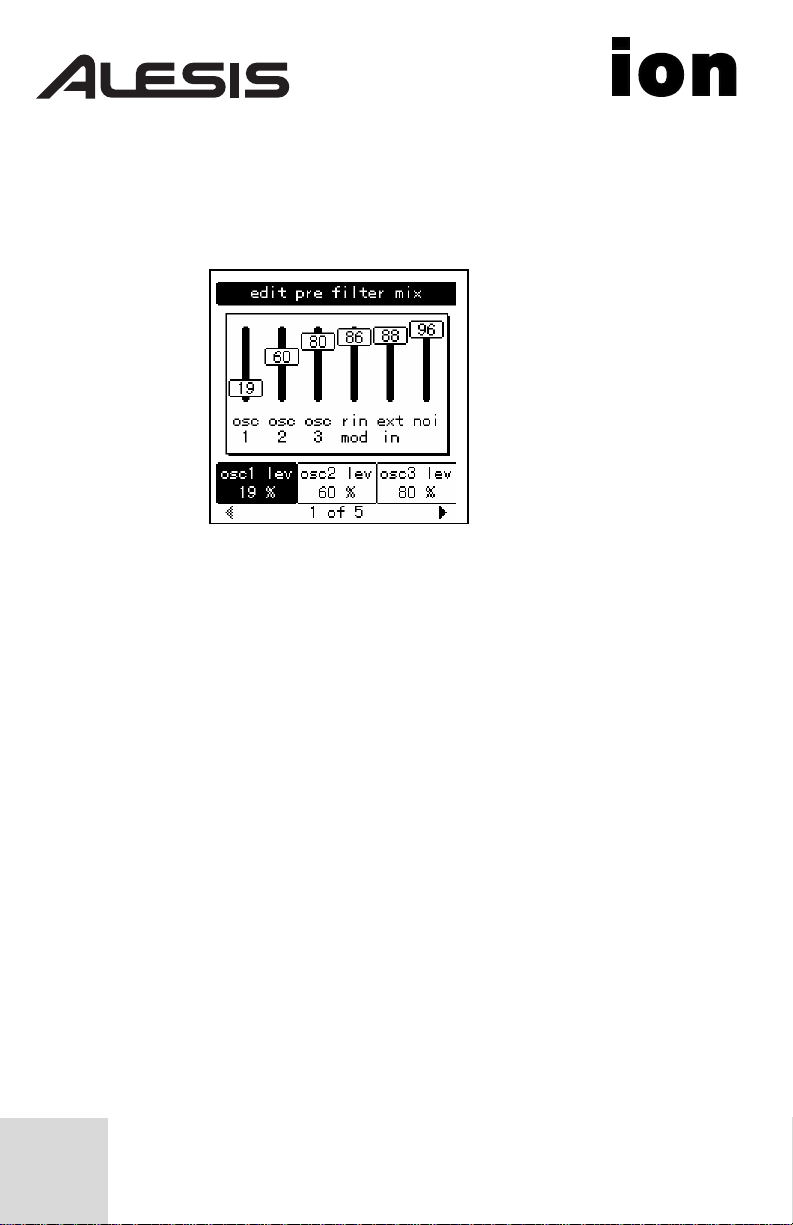
Sometimes there are several pages of parameters related to a given
function. You will know this is the case by looking on the bottom line of
the page, as in the example below:
The numbers at the bottom of the page tell you how many pages there
are, and which page you are on. In the above example, there are five
pages available, and you are on page 1. When more than one page is
available, you can navigate to the additional pages using the [page X]
and [W page] buttons. Note that the arrow in the left corner is “grayed
out.” That means that there are no more pages available in that direction.
The Global pages
• When the [global] button is pressed, the Ion will enter Global mode.
The Mod Matrix pages
• When the [mod matrix] button is pressed, the Ion will enter Edit
Select the desired parameter using a Soft button and turn the data
knob to edit the value. For a complete description of the Global
mode parameters, see Chapter 3 of your User Manual.
mode for the active Program and display parameters related to the
Mod Matrix. This is also where the Tracking Generator is found. For
a complete description of the Mod Matrix and the Tracking
Generator, see Chapter 6 of your User Manual.
4

LED functions
Two LEDs serve as “speed” indicators: the rate LED and the tempo LED.
The rate LED may blink at a different speed depending on which of
three functions has been selected in the LFO section: [lfo 1], [lfo 2], or
[s&h].
The mod LEDs indicate that an edit has been made in the Mod Matrix
that affects one or more of the parameters in the section where the mod
LED is lit. If it isn’t obvious at first which parameter is being “modded,”
press the [mod matrix] button and look at the lists of sources and
destinations. For more information on the Mod Matrix, see Chapter 6 of
your User Manual.
The loop LED is similar to the mod LEDs in that it indicates that the loop
parameter has been activated inside the selected envelope. More
information about looping the envelopes can be found on pages 71-72 of
your User Manual.
Button functions
[edit] buttons – A green LED indicates that an [edit] button has been
pressed. This means that a particular set of parameters is being shown in
the display for inspection and editing.
Selection buttons – Some buttons allow you to select between different
sets of parameters that share a common knob or set of knobs. For
example, the [lfo 1], [lfo 2], and [s&h] buttons determine which of those
three functions will be controlled by the rate knob, and also call up
parameters from that function in the display. Similarly, the [pitch/mod],
[filter], and [amp] buttons determine which of those three envelopes will
be controlled by the five knobs in the env section.
Parameter buttons – Other buttons edit or toggle the parameter under
their control: for example, the [mono/poly] button or the [octave]
buttons in the osc section. Other examples include the [porta] button,
5

which enables portamento, and the [waveform select] buttons, which
determine the waveform utilized by each oscillator.
Special cases
[tap tempo] button – This button allows you to match the speed of the
arpeggiator, an LFO, or other effects to the tempo of a song simply by
tapping the button in time to the music! The LED under the button
flashes to give you an idea of what the tempo setting is currently.
[transpose] and [octave] buttons – These three buttons control the
global transposition and octave shift of the Ion’s keyboard. The settings
will affect all programs and setups, as well as the MIDI note output.
Knob functions
volume knob – This is the red knob just above the Pitch wheel. It
controls the level of the main and headphone outputs. Note that this
control has no effect on the aux outputs.
tempo knob – This is the knob in the upper left corner of the Ion. It
controls the speed of any number of functions, most notably the
arpeggiator.
data knob – This is the clear knob to the right of the display. Use it for
fine-tuning your edits, or to edit a parameter that has no front-panel
knob. It is also used for selecting Programs and Setups.
Performance controls
The Ion gives you a number of expressive controls at your fingertips, in
addition to all of the knobs and buttons:
Velocity – The Ion’s keyboard will respond to differences in how hard
you play the keys. You can tailor-make the keyboard’s response to your
6

playing style by selecting one of the nine keyboard curves found on
Global mode page 1, Soft button 2.
(p) or Pitch Bend wheel – This wheel is normally assigned to bend the
pitch of one or more oscillators, but it may be used as a source in the
modulation matrix to control nearly any parameter.
(m1) wheel – This wheel usually adds vibrato, but it also may be used as
a source in the modulation matrix to control nearly any parameter.
(m2) wheel – This wheel usually sweeps the filter, but it also may be
used as a source in the modulation matrix to control nearly any
parameter.
7

This page intentionally left blank.
8
MANUAL DE INICIO RÁPIDO DEL USUARIO
(ESPAÑOL)
Diagrama de conexión
Conexión de la fuente de corriente alterna
Antes de realizar cualquier conexión eléctrica, asegúrese de que el
interruptor de alimentación de Ion está apagado.
1. Enchufe el extremo hembra del cable de alimentación a la toma de
2. Enchufe el extremo macho (del enchufe) a una toma de corriente
Conexiones de audio
• Estéreo. Conecte dos cables desde las salidas derecha e izquierda
• Auriculares. Enchufe unos auriculares en el jack de auriculares
corriente de Ion.
conectada a tierra correctamente.
de Ion a dos entradas de un amplificador o mezclador.
situado en el panel trasero.
9
Conexión de los pedales de pie
• Pedal con función «sustain». Está diseñado para trabajar con
cualquier interruptor de pie provisional estándar. El sintetizador Ion se
calibrará por sí solo con un pedal normalmente abierto o normalmente
cerrado si el pedal está enchufado cuando el sintetizador Ion esté
encendido.
• Pedal EXP. Está diseñado para funcionar con un pedal V-5 o
equivalente.
La pantalla
La pantalla de cristal líquido (LCD —Liquid Crystal Display—) está
colocado en el centro del sintetizador Ion de más de una manera.
Dependiendo del botón o perilla que usted haya activado, podría mostrar
el nombre del programa, qué programas se utilizan en un ajuste, los
valores de los parámetros que se están modificando o incluso una
representación gráfica de una forma de onda o un sobre.
La página de inicio
Esta es la pantalla que le muestra la información más variada de una sola
vez. Si aún no ha llegado a ella, pulse el botón [Home] y verá lo
siguiente:
He aquí el significado de cada una de las áreas de la pantalla de inicio
[Home]:
10
• La barra oscurecida en la parte superior de la pantalla le muestra el
nombre de la sección que está viendo en ese momento. En este
caso, se puede leer home (inicio).
• Justo debajo, se encuentran el número de banco y de programa.
• En el centro puede ver el nombre del programa de la parte activa.
• La cuarta línea empezando por abajo muestra el número de ajuste
[Setup].
• Debajo, el rectángulo marcado muestra el nombre actual del setup
(ajuste).
• Los iconos «e box» (caja e) a la derecha de los números de programa
y de ajuste indican que el programa y el ajuste han sido editados
respectivamente.
• El rectángulo rellenado en la segunda línea empezando desde abajo
muestra cual de las cuatro partes ha sido seleccionada con los
botones del panel activo [panel active].
Nota: El icono en la parte interior izquierda de este cuadro indica
que la parte actual ha sido puesta en «mute».
• El icono de la «nota negra», el símbolo de «equivalencia» (=) y los
números a su derecha le indican en qué nivel está el ajuste de
tempo para el ajuste.
• La «G» a la derecha del valor de tempo indica el ajuste de la fuente
de tempo del parámetro de modo Global. Si la «G» está allí, eso
significa que el parámetro de la fuente de tempo está configurado en
modo global. Esto causa que el tempo se mantenga igual cuando
usted accede a un nuevo ajuste (setup) o cambia de programas. Si la
«G» no está allí, el parámetro de la fuente de tempo está configurada
en modo programa. En este caso, el valor del tempo puede cambiar
de un ajuste a otro o cuando accede a otro programa en la parte A.
• El icono de «conector MIDI» y el número a su derecha indican el
Canal MIDI de la parte seleccionada.
11
 Loading...