

Alesis iO4 Quick Start Manual

QUICKSTART GUIDE
ENGLISH ( 3 – 9 )
MANUAL DE INICIO RÁPIDO
ESPAÑOL ( 10 – 16 )
GUIDE D'UTILISATION RAPIDE
FRANÇAIS ( 17 – 23 )
GUIDA RAPIDA
ITALIANO ( 24 – 30 )
KURZANLEITUNG
DEUTSCH ( 31 – 37 )

3
QUICKSTART GUIDE (ENGLISH)
1. Make sure all items listed in the Box Contents
are included.
2. READ SAFETY INSTRUCTION BOOKLET
BEFORE USING THE PRODUCT.
3. Place the product in an appropriate location
for operation.
4. Ensure high quality, shielded audio cables
are used away from sources of
electromagnetic interference.
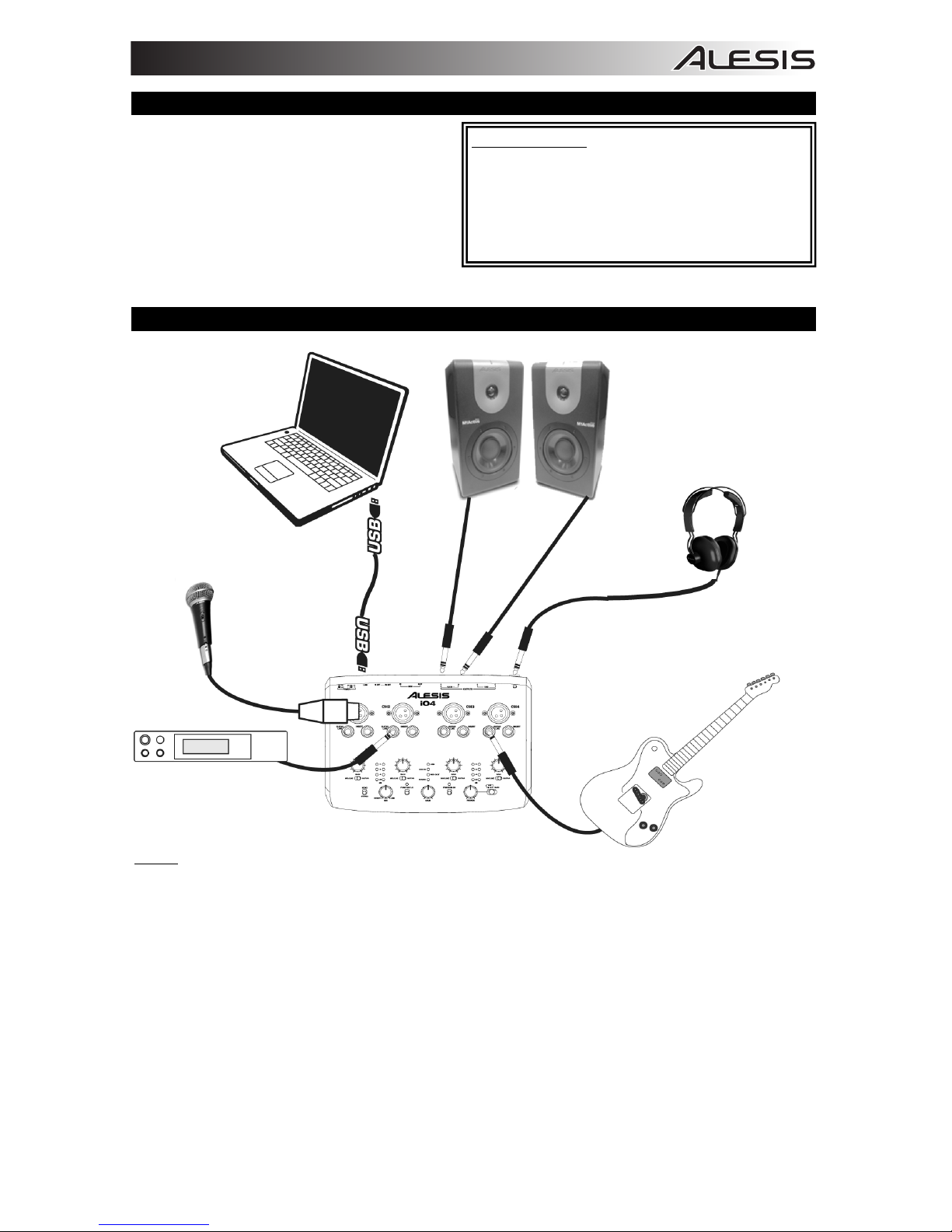
CONNECTION DIAGRAM
Notes:
y When recording a guitar or bass with an active pickup, set the iO4 's MIC/LINE / GUITAR SWITCH to
"MIC/LINE." If your instrument uses a passive pickup, set the switch to "GUITAR."
y Plug the iO4 directly into your computer, and avoid using a USB hub. Hubs can interfere with the iO4 's
audio and MIDI timing signals.
y To reduce electrical hum at high gain settings, keep the iO4 's power supply away from your guitar cable
and the iO4 's channel inputs.
Before turning on the iO4's power, do the following:
1. Ensure all cable connections have been made correctly.
2. Ensure the volume controls for your amplifier or speakers are turned down.
3. Insert the Power jack into the [POWER] input on the rear panel of the iO4 and plug the power adapter into
an AC outlet.
4. Then power-up the iO4.
5. Turn on the power of your amplifier or speakers, and adjust the Gain and Main volume controls on the
iO4.
BOX CONTENTS
y iO4
y Power adapter
y USB cable
y Software DVD
y Quickstart Guide
y Safety Instructions & Warranty Information booklet
HEADPHONE
MICROPHONE
COMPUTER
SAMPLER
GUITAR
SPEAKERS

4
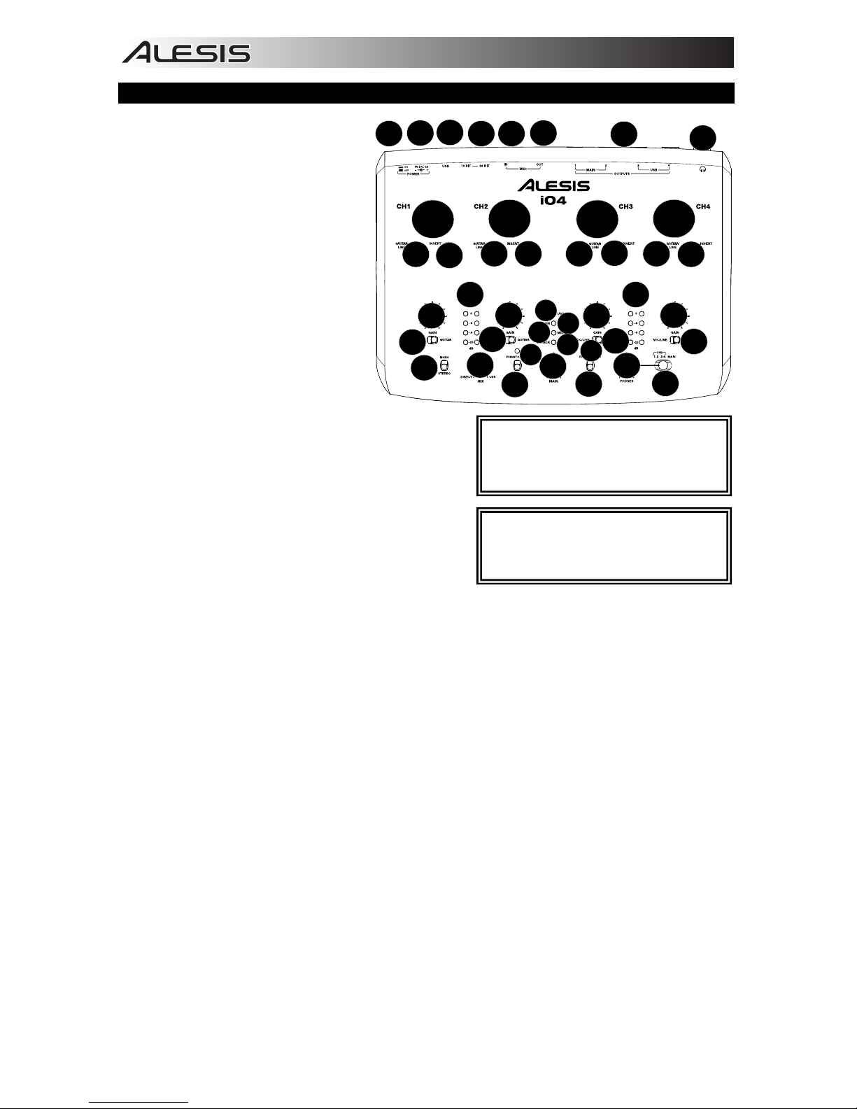
TOP PANEL FEATURES
1. MIC INPUT – Connect a
microphone to this input with
an XLR cable.
2. GUITAR / LINE INPUT –
Connect a line-level device or
guitar to this input with a 1/4"
cable.
3. INSERT – The insert jack
allows you to insert a
compressor, EQ, or any other
signal processor in between
the iO4's preamplifier and A/D
converter.
4. GAIN – Adjusts the channel
audio gain level.
5. MIC/LINE/GUITAR SWITCH –
When this switch is in the
"GUITAR" position, the
channel will serve as a highimpedance input for
connecting guitar or bass
instruments. When the switch is in the "MIC/LINE"
position, the channel will accept mic or line-level
signals.
6. USB LED – Lights up when a USB connection has
been established with your computer.
7. MIDI IN LED – Flashes whenever MIDI data is
received from an external MIDI device.
8. MIDI OUT LED – Flashes whenever MIDI data is
sent out of the iO4.
9. POWER LED – Lights up when unit is powered on.
10. MONO / STEREO – Adjusts the headphone mix and main mix for mono or stereo operation.
11. MONITOR MIX – Blend in any amount of zero-latency signal from your inputs with the output of your
computer.
12. PHANTOM POWER SWITCH – Individual toggle switches activate and deactivate phantom power for
channels 1+2 and channels 3+4. When activated, phantom power supplies +48V to the XLR mic inputs.
Please note that most dynamic microphones do not require phantom power, while most condenser
microphones do. Consult your microphone's documentation to find out whether it needs phantom
power.
13. PHANTOM POWER LED – Lights up when phantom power is engaged.
14. MAIN VOLUME – Adjusts the signal volume going to the MAIN OUTPUTS.
15. CHANNEL 1/2 VOLUME METER – Displays the signal level for input channels 1 and 2.
16. CHANNEL 3/4 VOLUME METER – Displays the signal level for input channels 3 and 4.
17. HEADPHONE VOLUME – Adjusts the volume level of the headphone output.
18. HEADPHONE MONITOR MIX – Adjust this switch to monitor the USB OUTPUT (channels 1 and 2),
USB OUTPUT (channels 3 and 4), or the direct mix of 4 input channels: channels 1 and 3 in the left
headphone output and channels 2 and 4 in the right headphone output and the USB output.
NOTE: Do not use the MIC INPUT and
GUITAR/LINE INPUT at the same time on
one channel. This may overload the
channel and cause distortion.
1
1
1
1
2
2 2 2
3
3
3
3
4
4
4
4
5
5
5
5
6
7
8
9
10
11
12
12
13
13
14
15 16
19
17
18
20
21
2223
24
25
26
NOTE: Turning on phantom power will
cause a momentary jump in the LED
meters and a dropout in audio.

5
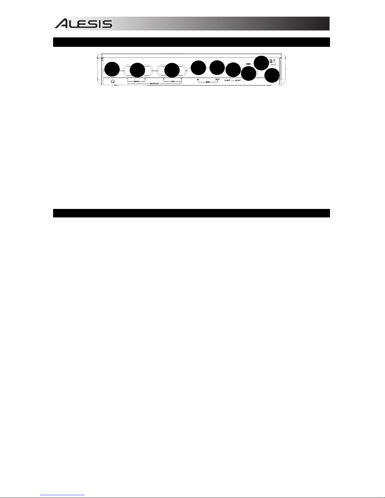
REAR PANEL FEATURES
19
20
21
22
23
24
26
20
25
19. HEADPHONES – Connect your 1/4" headphones to this output.
20. OUTPUTS – Use standard 1/4" cables to connect these outputs to a mixer, speakers, or an amplifier
system. The level of these outputs is controlled by the MAIN VOLUME knob.
21. MIDI OUT – Use a standard five-pin MIDI cable to connect this output to the MIDI IN of an external
MIDI device.
22. MIDI IN – Use a standard five-pin MIDI cable to connect this input to the MIDI OUT of an external MIDI
device.
23. 16/24 BIT MODE – When the switch is set to 24 bit, you can use inputs 1-2 and outputs 1-2. When the
switch is set to 16 bit, you can use channel inputs 1-4 and outputs 1-4.
24. USB PORT – Use the included USB cable to connect the iO4 to a computer. iO4 requires a USB 2.0
connection. Note that the iO4 is not USB bus powered.
25. POWER CONNECTOR – Plug the included AC adapter here (6v DC 1A)
26. POWER SWITCH – Turns the iO4's on/off.
SYSTEM REQUIREMENTS
Minimum PC Requirements:
• Pentium III 450 MHz Processor
• 512 MB RAM
• Available USB 2.0 Port
• Windows XP (with Service Pack 2 installed)
Recommended PC Requirements:
• Pentium 4 or Athlon Processor
• 2GB or more RAM
• 7,200 RPM Hard Disk Drive
• Available USB 2.0 Port
• Windows XP, (with Service Pack 2 installed),
Vista, 7
Minimum Macintosh Requirements:
• Apple computer with native USB 2.0 support
• Mac OS X 10.5 or later
• 512 MB RAM
Recommended Macintosh Requirements:
• Mac computer with an Intel Core 2 Duo, Core
i3, Core i5, Core i7, or Xeon processor
• 7,200 RPM Hard Disk Drive
• 2GB of memory
• OS X v10.6.6 or later

6
AUDIO SETUP
The iO4 is a class-compliant device that can be used with any digital audio workstation or recording software
that supports USB audio. To enable your iO4 to send and receive audio to and from your computer, follow
the instructions below for your computer's operating system:
WINDOWS 7:
1. Use the included USB cable to connect the iO4 to your
computer.
2. Go to Start Menu f Control Panel f Hardware and
Sound f Sound.
3. Click the Playback tab and select iO4 as the default
device.
4. Click the Recording tab and select iO4 as the default device.
5. Click Properties in the lower right-hand corner.
6. In the new window, click the Advanced tab and select 2channel, 16-bit, 44100 Hz (CD Quality) as the default
format.
7. Uncheck both boxes under Exclusive Mode.
8. Click the Levels tab and set the slider to "5."
9. Click OK to close the Properties window.
10. Click OK to close the Sound control panel.
WINDOWS VISTA:
1. Use the included USB cable to connect the iO4 to your
computer.
2. Go to Start Menu f Control Panel f Sound. (If you don't see Sound, select Switch to Classic
View, and the Sound Control Panel should become available.)
3. Click the Playback tab and select iO4 as the default device.
4. Click the Recording tab and select iO4 as the default device.
5. Click Properties in the lower right-hand corner.
6. In the new window, click the Advanced tab and select 2-channel, 16-bit, 44100 Hz (CD Quality) as
the default format.
7. Uncheck both boxes under Exclusive Mode.
8. Click OK to close the Properties window.
9. Click OK to close the Sound control panel.
WINDOWS XP:
1. Use the included USB cable to connect the iO4 to your computer.
2. Go to Start Menu f Control Panel f Sounds and Audio Devices.
3. Click the Audio tab.
4. Under Sound Playback and Sound Recording, select iO4 as the default device.
5. Click OK.
MAC:
1. Use the included USB cable to connect the iO4 to your computer. Then go to Applications f Utilities
f Audio Midi Setup.
2. In the Audio Devices tab select the System Settings menu.
3. In the Audio Devices Menu, right click on iO4.
4. Select "Use this device for sound input".
5. Select "Use this device for sound output".
6. Quit Audio Midi Setup.
Be sure your audio software program is
set up to receive audio from the iO4.
This can usually be done in your
software's "Preferences" or "Device
Setup." Please consult your software
manual for more information.
For recording of more than two
channels of audio (or if you experience
too much latency after adjusting your
software latency settings), we
recommend the free ASIO4ALL (Audio
Stream Input/Output) driver for PC at
www.asio4all.com
. ASIO drivers
generally perform better and with lower
latency since they create a more
efficient communication between audio
devices and software.

7
SETTING UP THE SOFTWARE (WINDOWS AND MAC)
ACTIVATING CUBASE LE 5
1. Install Cubase LE 5.
2. Make sure that your computer has a working Internet connection to activate the license because the
eLicenser Control Center (eLCC) needs to register with the Steinberg license server.
3. Make sure that you have the latest version of the eLCC installed from www.elicenser.net
.
4. Open the eLicense Control Center (eLCC) software and make a note of your Soft-eLicenser number. If
you do not see your number, click the "Support" menu and select "Update eLicenser License
Database."
5. Create a user account in the MySteinberg area at www.steinberg.net
. If you already have one, please
go to Step 7.
6. Check your email and activate your user account by clicking the link in the confirmation email. If the link
does not work, copy and paste the link into your browser's address bar.
7. Log in to your MySteinberg account, and click on "Activation & Reactivation", choose "Cubase LE 5"
and select "Permanent Activation". Enter your Soft-eLicenser and choose your hardware manufacturer.
8. You will receive an email containing the activation code.
9. Launch the eLicenser Control Center software. Click the "Enter Activation Code" button to download
the license for your Steinberg product to the Soft-eLicenser. Enter the required activation code into the
corresponding field. Follow the instructions on screen.
10. After activating your software, open Cubase to begin using it.
Attention Windows Users:
If you see a "permissions" error message when trying to open the software,
follow these steps:
1. Right-click the Cubase icon on your Desktop.
2. Select Properties.
3. Select the Compatibility tab.
4. Under "Privilege Level," check the box that says "Run this program as an administrator."
5. Click "Apply" then "OK."
8
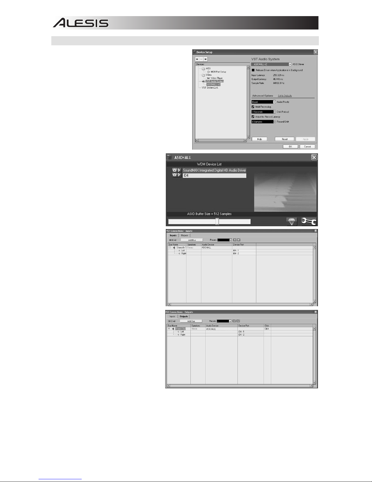
WINDOWS SETUP
Once Cubase LE 5 is installed and activated, follow
the steps below to configure the software to record
with your iO4.
1. Open Cubase LE 5. If prompted to open a
project, cancel for now.
2. From the menus select Devicesf Device
Setup.
3. In Device Setup click on VST Audio System.
4. In the ASIO driver dropdown box, select
ASIO4ALL. When asked to switch the driver,
select 'Yes'. Then select ASIO4ALL from the left
panel and click on the Control Panel button at
the top right of the window.
5. Click on the image of the wrench in the bottom
right corner and ensure that "iO4" is
selected for the input and output
device. Uncheck any other devices
listed here and then close the
window.
6. Click OK for the two windows that are
open.
7. In Cubase, click on FilefNew
Project and select Empty, and
choose where you would like to save
your project.
8. Click on the Device menu at the top
of the screen and select VST
Connections. Click on Inputs at the
top of the window. Click on the input
titled under the Bus Name column.
Create a Stereo input bus by clicking
on the Add Bus button and selecting
the Stereo configuration. Name the
preset, and click OK.
9. Under the Audio Device column,
select ASIO4ALL.
10. In the Device Port column, select
"iO4 -1" for the Left stereo input and
"iO4 - 2" for the right stereo input.
11. Click on the Outputs tab, select your
output device in the exact same way
you set up your input device as the
Audio Device.
12. Close the VST Connections window.
13. Right click in the main project window
and choose Add Audio Track.
14. In the Audio Track Configuration
window, select '1 – Stereo' and click
OK.
15. Activate the Track Monitor button on
the Stereo track, found next to the
Record Enable button. Click the Record button at the top of the Cubase window, do a quick test, and
stop the recording.
16. Rewind to the beginning of the track and press the play button at the top of the Cubase window to hear
what you just recorded.
Note: To avoid having to set the VST Audio System and VST Connections each time you open Cubase, you
can save a your settings as a template by going to Filef Save as Template. Then when you reopen Cubase
your template will appear in the Project Templates list.
9
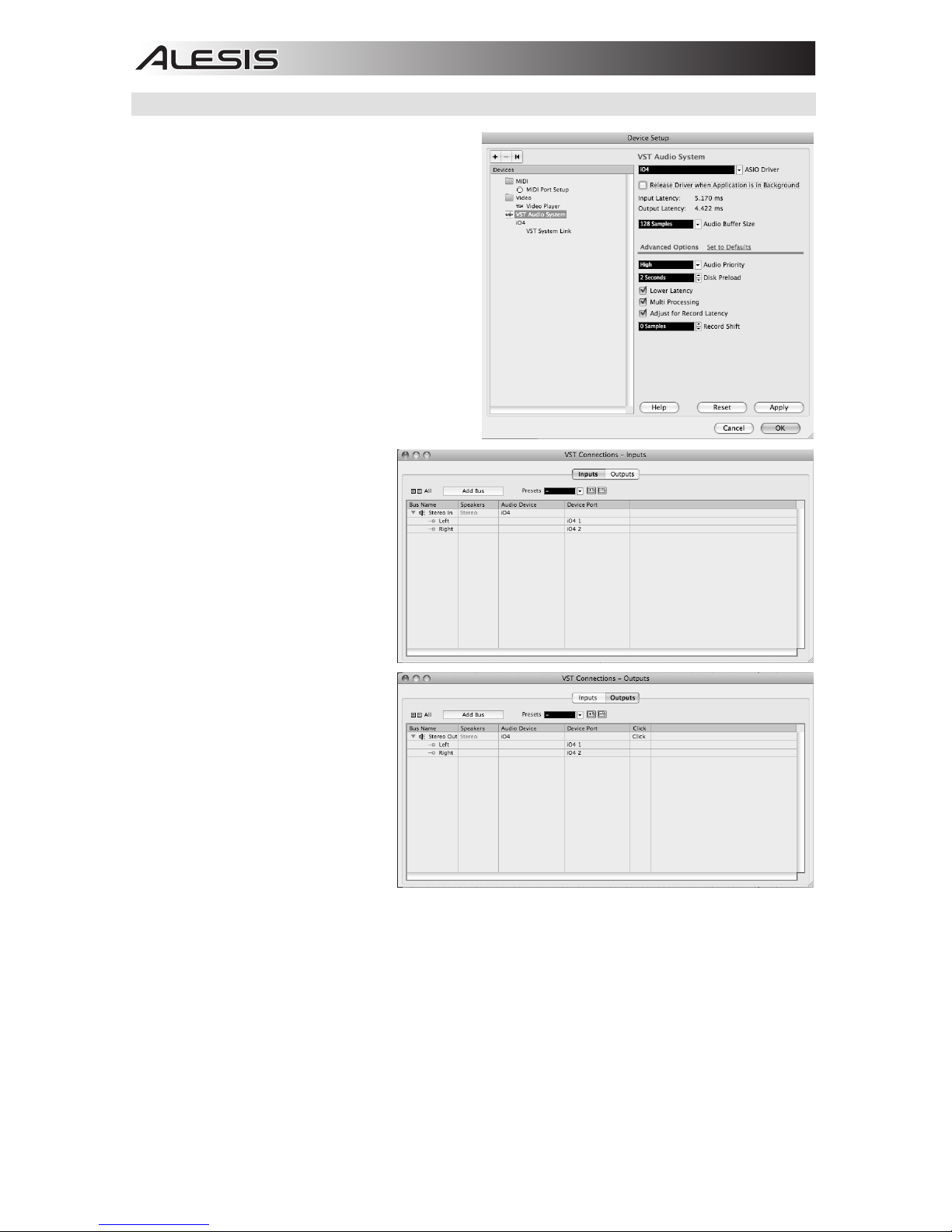
MAC SETUP
Once Cubase LE 5 is installed and activated, follow
the steps below to configure the software to record
with the iO4.
1. Open Cubase LE 5. If prompted to open a
project, cancel for now.
2. From the menus select Devicesf Device
Setup.
3. In Device Setup click on VST Audio System.
4. In the ASIO driver list on the right side of the
Device Setup, select iO4. Click OK.
5. In Cubase, click on FilefNew Project and
select Empty, and choose where you would
like to save your project.
6. Click on the Device menu at the top of the
screen and select VST Connections. Click on
Inputs at the top of the window. Click on the
input titled under the Bus Name column.
Create a Stereo input bus by clicking on the
Add Bus button and selecting
the Stereo configuration. Name
the preset, and click OK.
7. Under the Audio Device column,
select iO4.
8. In the Device Port column, select
"iO4 1" for the Left stereo input
and "iO4 2" for the right stereo
input.
9. Click on the Outputs tab, and for
the left stereo output device
select "iO4 1" and for the right
stereo output device select "iO4
2".
10. Close the VST Connections
window.
11. Right click in the dark blue area
of the main project and choose
Add Audio Track.
12.
In the Audio Track Configuration
window, select 1 – Stereo and
click OK.
13. Activate the Track Monitor button
on the Stereo track, found next to
the Record Enable button. Click
the Record button at the top of
the Cubase window, do a quick
test, and stop the recording.
14. Rewind to the beginning of the track, disable the track monitor button and then press the play button at
the top of the Cubase window to hear what you just recorded.
Note: To avoid having to set the VST Audio System and VST Connections each time you open Cubase, you
can save a your settings as a template by going to Filef Save as Template. Then when you reopen Cubase
your template will appear in the Project Templates list.

10
GUÍA DE INICIO RÁPIDO (ESPAÑOL)
1. Asegúrese de que estén presentes todos los
elementos enumerados en Contenido de la caja.
2. LEA EL FOLLETO DE INSTRUCCIONES DE
SEGURIDAD ANTES DE UTILIZAR EL PRODUCTO.
3. Coloque el producto en un lugar adecuado para su
funcionamiento.
4. Asegúrese de usar cables de audio blindados de alta
calidad y alejados de las fuentes de interferencia
electromagnética.
DIAGRAMA DE CONEXIÓN
Notas:
y Cuando grabe una guitarra o bajo con un captador activo, ajuste el interruptor MIC/LINE / GUITAR del
iO4 a "MIC/LINE". Si su instrumento utiliza un captor pasivo, ajuste el conmutador a "GUITAR".
y Enchufe el iO4 directamente a su computadora y evite usar un concentrador (hub) USB. Los
concentradores pueden interferir con las señales de sincronización de audio y MIDI del iO4
y Para reducir el zumbido eléctrico cuando se usan ajustes altos de ganancia, mantenga la fuente de
alimentación del iO4 alejada del cable de su guitarra y de las entradas de los canales del equipo.
Antes de encender el iO4, haga lo siguiente:
1. Asegúrese de que todas las conexiones de cables hayan sido realizadas correctamente
2. Asegúrese de que los controles de volumen de su amplificador o altavoces se ajustaron al mínimo
3. Inserte el conector de alimentación en la entrada [POWER] del panel trasero del iO4 y enchufe el
adaptador de alimentación a un tomacorriente de CA.
4. Luego, encienda el iO4.
5. Encienda su amplificador o altavoces y ajuste los controles Gain (Ganancia) y Main (Volumen principal)
del iO4.
CONTENIDO DE LA CAJA
y iO4
y Adaptador de alimentación
y Cable USB
y DVD de software
y Guía de inicio rápido
y Folleto de instrucciones de seguridad
e información sobre la garantía
AURICULARES
COMPUTADORA
GUITARRA
MICRÓFONO
SAMPLER
ALTAVOCES
11
CARACTERÍSTICAS DEL PANEL SUPERIOR
1. ENTRADA DE MICRÓFONO –
Conecte a esta entrada un
micrófono con un cable XLR.
2. ENTRADA DE GUITARRA / LÍNEA
– Conecte a esta entrada un
dispositivo de nivel de línea o una
guitarra con cables de 1/4".
3. INSERCIÓN – El conector de
inserción permite insertar un
compresor, un ecualizador o
cualquier otro procesador de señal
entre el preamplificador y el
conversor A/D del iO4.
4. GANANCIA – Se utiliza para ajustar
el nivel de ganancia de audio del
canal.
5. CONMUTADOR DE MICRÓFONO /
LÍNEA / GUITARRA – Cuando este
conmutador está en la posición
"GUITAR" el canal sirve como entrada de alta
impedancia para conectar guitarras o bajos. Cuando
está en la posición "MIC/LINE", el canal acepta
señales de micrófono o de nivel de línea.
6. LED DE USB – Se enciende cuando se establece una
conexión USB con su computadora.
7. LED DE ENTRADA MIDI – Destella toda vez que se
reciben datos MIDI desde un dispositivo MIDI externo.
8. LED DE SALIDA MIDI – Destella toda vez que se
envían datos hacia afuera del iO4.
9. LED DE ENCENDIDO – Se ilumina cuando se
enciende el equipo.
10. MONO / ESTÉREO – Se utiliza para ajustar la mezcla para auriculares o la mezcla principal para
funcionamiento mono o estéreo.
11. MEZCLA PARA MONITOR – Combine cualquier valor de señal de latencia cero de sus entradas con
la salida de su computadora.
12. INTERRUPTOR DE ALIMENTACIÓN FANTASMA – Interruptor individual que activa y desactiva la
alimentación fantasma de los canales 1+2 y los canales 3+4. Cuando se activa, la alimentación
fantasma suministra +48 V a las entradas de micrófono XLR. Tenga en cuenta que la mayoría de los
micrófonos dinámicos no requieren alimentación fantasma, mientras que la mayoría de los micrófonos
de condensador la requieren. Consulte la documentación de su micrófono para averiguar si necesita
alimentación fantasma.
13. LED DE ALIMENTACIÓN FANTASMA– Se enciende cuando se acopla la alimentación fantasma.
14. VOLUMEN PRINCIPAL – Ajusta el volumen de las salidas MAIN (Principal).
15. MEDIDOR DE VOLUMEN DE CANALES 1/2 – Muestra el nivel de señal de los canales de entrada 1 y
2.
16. MEDIDOR DE VOLUMEN DE CANALES 3/4 – Muestra el nivel de señal de los canales de entrada 3 y
4.
17. VOLUMEN DE AURICULARES – Se utiliza para ajustar el nivel de volumen de la salida para
auriculares.
18. MEZCLA DE MONITOR PARA AURICULARES – Ajuste este conmutadora para monitorear la
SALIDA USB (canales 1 y 2), la SALIDA USB (canales 3 y 4) o la mezcla directa de los 4 canales de
entrada: canales 1 y 3 en la salida para el auricular izquierdo y canales 2 y 4 en la salida para el
auricular derecho y la salida USB.
NOTA: No utilice las entradas MIC y
GUITAR/LINE al mismo momento en un
canal. Si lo hace, se puede sobrecargar
el canal
y
causar distorsión.
1
1
1
1
2
2 2 2
3
3
3
3
4
4
4
4
5
5
5
5
6
7
8
9
10
11
12
12
13
13
14
15 16
19
17
18
20
21
2223
24
25
26
NOTA: Al encender la alimentación
fantasma se produce un salto
momentáneo en los medidores de LED y
un bajón del audio.
12
CARACTERÍSTICAS DEL PANEL TRASERO
19
20
21
22
23
24
26
20
25
19. AURICULARES – Conecte sus auriculares de ¼" a esta salida.
20. SALIDAS – Use cables estándar TRS de 1/4" para conectar estas salidas a un mezclador, altavoces o
sistema de amplificador. El nivel de estas salidas está controlado por la perilla MAIN (Volumen
principal).
21. SALIDA MIDI – Use un cable MIDI estándar de cinco pines para conectar esta salida a la ENTRADA
MIDI de un dispositivo MIDI externo.
22. ENTRADA MIDI – Use un cable MIDI estándar de cinco pines para conectar esta entrada a la SALIDA
MIDI de un dispositivo MIDI externo.
23. MODO DE 16/24 BITS– Cuando el conmutador se ajusta a 24 bits, puede usar las entradas 1-2 y las
salidas 1-2. cuando el conmutador se ajusta a 16 bits, puede usar las entradas de canales 1-4 y las
salidas 1-4.
24. PUERTO USB – Use el cable USB incluido para conectar el iO4 a una computadora. iO4 requiere una
conexión USB 2.0. Tenga en cuenta que el iO4 no está alimentado por el bus USB.
25. CONECTOR DE ALIMENTACIÓN – Enchufe aquí el adaptador de CA incluido (6 V CC 1 A)
26. INTERRUPTOR DE ENCENDIDO – Se utiliza para encender y apagar el iO4.
REQUISITOS DE SISTEMA
Requisitos mínimos de PC:
• Procesador Pentium III de 450 MHz
• 512 MB de RAM
• Puerto USB 2.0 disponible
• Windows XP (con Service Pack 2 instalado)
Requisitos de PC recomendados:
• Procesador Pentium 4 o Athlon
• 2GB or more de RAM
• 7,200 RPM Hard Disk Drive
• Puerto USB 2.0 disponible
• Windows XP (con Service Pack 2 instalado),
Vista, 7
Requisitos mínimos de Macintosh:
• Computadora Apple con soporte de USB 2.0
nativo
• Mac OS X 10.5 o posterior
• 512 MB de RAM
Requisitos de Macintosh recomendados:
• Procesador Intel Core 2 Duo, Core i3, Core i5,
Core i7, or Xeon
• 7,200 RPM Hard Disk Drive
• 2GB of memory
• OS X v10.6.6 or later
 Loading...