


Handpiece Controls |
Overview |
|
|
Controls
Holders
This section provides information related to the servicing, maintenance, and adjustment of handpiece controls. Detail on how to service control heads, control blocks, and troubleshoot specific problems related to them is presented.
Additional information covered in this section includes assembly, service, and maintenance information for A-dec handpiece holders. Flow diagrams, replacement part information, and troubleshooting tips are presented.
85.0812.00, 2003 |
HC-1 |
Handpiece Controls |
Handpiece Control Adjustments |
|
|
Making Handpiece Control Adjustments |
|
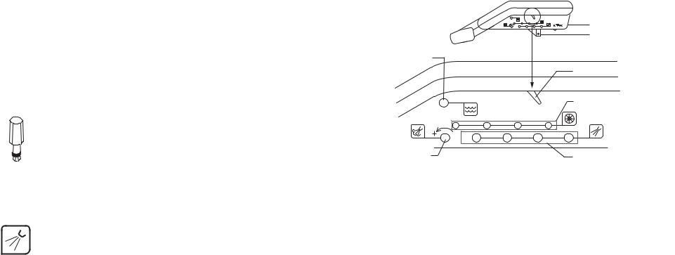
Location of Control Adjustments
The control adjustments for the handpiece flush control, drive air pressure, coolant air flow, and coolant water flow are located on the side of the control head.
Operators Adjustments
Use the adjustment key to make adjustments, with the exception of the drive air pressure. The adjustment key will not fit the drive air control ports. This was done to prevent unintentional changes to drive air settings. To adjust the drive air, use a 3/32" hex key.
Handpiece flush control
|
|
|
|
Master On/Off toggle |
PUSH |
I |
MASTER |
O |
Drive air pressure controls |
|
||||
1 |
2 |
3 |
|
4 |
Coolant air flow control |
Coolant water |
|
|
|
flow controls |
Location of Control Adjustments on the Control Head
Adjusting
Coolant Water
Using the adjustment key or a 1/8" hex key, follow these steps to adjust the coolant water flow for each handpiece. Turn the key clockwise to decrease the coolant water flow and counterclockwise to increase the coolant water flow.
Task Description
1Insert the key into the adjustment port for the handpiece being adjusted.
2Turn clockwise until it seats softly.
3 Move the foot control’s wet/dry toggle to the ON position (toward blue dot).
4Run the handpiece at medium speed.
85.0812.00, 2003 |
5 |
Adjust the coolant water until 2-3 drops per second are visible. |
HC-2 |

Handpiece Controls |
Handpiece Control Adjustments |
|
|
Adjusting Coolant
Air
Adjusting
Drive Air
Using the adjustment key (or a 1/8" hex key), follow these steps to adjust the coolant air flow for each handpiece. Turn the key clockwise to decrease the coolant air flow and counterclockwise to increase the coolant air flow.
Task Description
1 Insert the key into the adjustment port (one location for all handpieces).
2Run the handpiece at medium speed.
3Adjust the coolant air by turning the key counterclockwise (until a fine mist is visible around the bur).
Follow these steps to adjust the drive air using a 3/32" hex key.
Task Description
1Install the handpiece on a drive air pressure gauge.
2 Locate drive air control for the handpiece being adjusted and insert the hex key.
3Install the handpiece gauge on the coupler.
4Move the foot control’s wet/dry toggle to OFF (away from blue dot) and fully depress the foot control cover.
5Turn the drive air control counterclockwise until the handpiece is running slightly above the manufacturer’s specified drive air pressure, then turn clockwise until it is at the specified pressure.
6Repeat adjustments 1-5 for each handpiece position.
85.0812.00, 2003 |
HC-3 |

Handpiece Controls |
Delivery Systems |
|
|
Working with Delivery Systems
The following pages provide instructions and service information on parts associated with A-dec’s delivery systems.
|
Continental whip |
Unitized holder |
assemblies |
78 |
456 |
123 |
Oil collector
Oil collector
Individual holder
Cascade Traditional Delivery System |
Cascade Continental Delivery System |
85.0812.00, 2003 |
HC-4 |

Handpiece Controls |
Oil Collector |
|
|
Oil Collector
|
Item # |
Part Number |
Description |
|
|
1 |
— |
Clear tubing, 1/4" |
|
|
|
|
|
|
|
2 |
— |
Oil collector manifold |
|
|
|
|
|
|
|
3 |
24.0416.00 |
Cap |
|
|
|
|
|
|
|
4 |
— |
Gauze pad |
|
|
|
|
|
|
|
5 |
052.023.00 |
Jar |
|
|
|
|
|
|
|
6 |
023.045.02 |
Inline barbs |
|
|
|
|
|
|
|
7 |
— |
Deflector spacer |
|
|
|
|
|
|
|
8 |
006.009.00 |
Nut |
|
|
|
|
|
|
|
9 |
013.090.00 |
Spring |
|
|
|
|
|
|
6
2
3
7
8
4
9
5
Oil Collector
85.0812.00, 2003 |
HC-5 |

Handpiece Controls |
|
|
Traditional Holders |
||
Individual Holder |
|
|
|
|
|
Item # |
Part Number |
Description |
|
|
|
1 |
99.0583.00 |
Auto holder assy |
2 |
|
|
|
99.0584.00 |
Assistant’s holder assy |
|
|
|
2 |
45.0403.00 |
Friction pad |
3 |
|
|
|
|
|
|
|
|
3 |
007 |
|
1 |
|
|
4 |
99.0590.00 |
Actuator, auto holder |
4 |
|
6 |
5 |
33.0025.01 |
Air bleed valve (individual) |
|
|
|
6 |
99.0587.00 |
Slot plug |
5 |
|
|
|
|
|
|
|
|
Unitized Holder |
|
|
|
|
|
Item # |
Part Number |
Description |
|
|
Holder |
1 |
99.0603.00 |
Traditional, 3-position |
|
|
|
|
|
|
|||
|
99.0604.00 |
Traditional, 4-position |
|
|
|
|
99.0605.00 |
Traditional, 5-position |
|
|
|
|
99.0606.00 |
Traditional, 6-position |
|
|
|
2 |
33.0132.00 |
Air bleed valve (unitized) |
|
|
7 |
|
|
|
|||
3 |
99.0590.00 |
Actuator, auto holder |
|
|
|
4 |
45.0403.00 |
Friction pad |
|
2 |
|
|
|
|
|||
5 |
007.056.00 |
Setscrew, socket cup point |
|
3 |
|
|
|
|
|
|
|
6 |
|
|
1 |
|
|
7 |
99.0587.00 |
Slot plug |
|
|
|
|
|
|
|
4 |
5 |
NOTE: |
Complete holder replacement is recommended if a holder is |
|
|
|
|
|
broken. For more information on service parts, see the |
Unitized Holder |
and Three-Position) |
||
|
Genuine A-dec Service Parts Catalog (P/N 85.5000.00) or |
||||
contact customer service.
85.0812.00, 2003 |
HC-6 |
Handpiece Controls |
Traditional Holder Flow Diagrams |
|
|
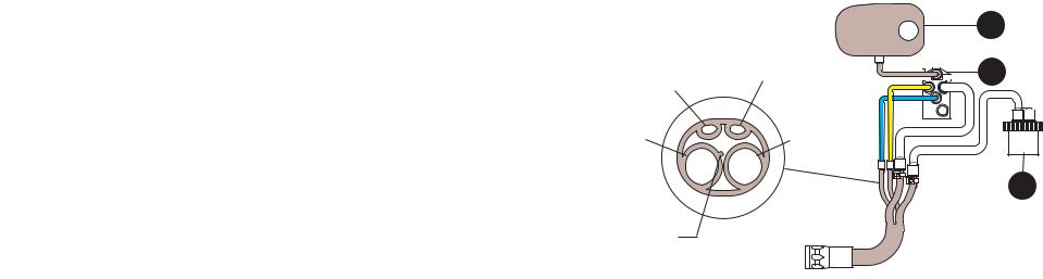
Traditional Holder
|
Item # |
Part Number |
Description |
|
|
1 |
99.0584.00 |
Single molded holder, assistant, Surf 4 |
|
|
|
|
|
|
|
|
99.0583.00 |
Single molded holder, auto, Surf 4 |
|
|
|
|
|
|
|
|
99.0629.00 |
2-position unitized holder, LH |
|
|
|
|
|
|
|
|
99.0619.00 |
3-position unitized holder, LH |
|
|
|
|
|
|
|
|
99.0628.00 |
2-position unitized holder, RH |
|
|
|
|
|
|
|
|
99.0618.00 |
3-position unitized holder, RH |
|
|
|
|
|
|
|
2 |
38.0509.00 |
Century Plus control block |
|
|
|
|
|
|
|
3 |
24.0410.00 |
Oil collector |
|
|
|
|
|
|
Coolant water |
Coolant air |
|
|
Drive air |
Exhaust |
Rib identifies drive air
A |
D1 |
|
W |
|
D2 |
1
2
3
Holder and Handpiece Tubing to Control Block
85.0812.00, 2003 |
HC-7 |

Handpiece Controls |
Continental Holders |
|
|
Cascade Continental Whip Assembly |
|
Item # |
Part Number |
Description |
|
1 |
002.034.01 |
Screw, button head socket |
|
2 |
39.1054.00 |
Continental whip assembly |
|
3 |
33.0025.01 |
Air bleed valve, long stem |
|
4 |
013.015.00 |
Spring, Red (standard 3 lb pull) |
1 |
|
|||
|
013.027.00 |
Spring, Green (optional 4 lb pull) |
|
5 |
39.1053.00 |
Spring rod |
|
2
3
45
Whip Assembly
85.0812.00, 2003 |
HC-8 |

Handpiece Controls |
Continental Holders |
|
|
Continental Whip
|
Item # |
Part Number |
Description |
|
1 |
|
1 |
39.1060.00 |
Whip |
|
|
|
|
|
|
|
|
|
2 |
001.026.00 |
Screw, socket head |
|
|
|
|
|
|
|
|
|
3 |
75.0066.00 |
Pivot wheel |
|
|
|
|
|
|
|
|
|
4 |
39.1055.00 |
Post |
|
|
|
|
|
|
|
|
|
5 |
001.121.01 |
Screw, socket head |
|
|
|
|
|
|
|
|
|
6 |
011.091.00 |
Spring pin |
|
|
|
|
|
|
|
|
|
7 |
39.1059.00 |
Whip ring |
|
|
|
|
|
|
|
|
|
8 |
75.0067.00 |
Pivot wheel |
|
|
|
|
|
|
|
|
|
9 |
004.162.00 |
Spring washer |
|
|
|
|
|
|
|
|
|
10 |
002.034.01 |
Screw, button head |
|
|
|
|
|
|
|
|
|
11 |
39.1050.00 |
Short pin |
|
|
|
|
|
|
|
|
|
12 |
007.010.00 |
Setscrew |
|
|
|
|
|
|
|
|
|
13 |
39.1052.00 |
Mounting bracket |
|
|
|
|
|
|
|
|
NOTE: Spring washer curve is towards the whip assembly(ies).
10
9 

 11
11
6
3  2
2
4
Spring washer
5
NOTE: Pre-load the spring by rotating it clockwise
until both hooks point up.
Spring
34.1054.00 Continental Whip Assembly
85.0812.00, 2003 |
HC-9 |
 Loading...