


 Loading...
A-dec 300® System
I N S T A L L A T I O N G U I D E
C O N T E N T S |
|
Introduction ................... |
1 |
Install the Chair ............... |
3 |
Install the Support Center |
..9 |
Install the Assistant's |
|
Instrumentation ............. |
15 |
Install the Delivery System 22 |
|
Install the Dental Light .... |
34 |
Install the Monitor Mount . 36 |
|
Install the Contoured Floor |
|
Box ............................ |
37 |
Install the Remote Floor |
|
Box ............................. |
39 |
Connect the Utilities ....... |
40 |
Install the Cuspidor ........ |
60 |
Install Upholstery ........... |
61 |
Prepare and Adjust the |
|
System ........................ |
64 |
Level the System ........... |
77 |
Touchpad Settings .......... |
80 |
Test the System ............. |
93 |
Verify Proper Clearance |
|
Between the Cuspidor Bowl |
|
and the Armrest ............ |
94 |
Install the Covers ........... |
96 |
Appendix: Install the Air |
|
Vacuum System (AVS) ..... |
105 |
Regulatory Information ... |
108 |
NOTE Information that is critical to a successful and safe installation is shaded like this note throughout the guide.
I N T R O D U C T I O N
This document contains installation instructions for the A-dec 300 system.
Before you begin:
•Clear the room of all debris and thoroughly clean the floors.
•Check that manual air and water shut-offs are installed.
•Purge any debris from air and water lines.
•Check with local building and code authorities about installation requirements. They differ from state to state and internationally.
Your installation may not require all components described in this document. Before you begin:
1.Assess what modules you will install.
2.Use “Installation Sequence” on page 2 to note the order of the modules that are to be installed.
86.0087.00 Rev E

A-dec 300 System Installation Guide
Recommended Tools
Tools Needed For This Installation
Hex key set |
Drill |
Drill bits: 3/8" wood, 1/4" and 1/2" masonry |
5/16" hex key driver |
Diagonal cutters |
A-dec silicone lubricant |
Ball driver set |
Needle nose and standard pliers |
Umbilical snake |
Adjustable wrench |
Phillips head screwdriver |
Rubber mallet |
3/4" and 9/16" socket and ratchets |
Roto hammer drill |
Sleeve pusher |
1/4", 1/2", and 3/4" combination |
Magnetic level |
Voltmeter |
wrenches |
|
|
Tape measure |
Pliers |
|
|
|
|
Installation Sequence
Modules for the A-dec 300 system installation are shown in Figure 1. Install the modules for your configuration in the order they are listed.
Figure 1. A-dec 300 System Shipping Boxes
|
|
NOTE The box for each module contains |
|
|
|
all of the parts needed to install that |
|
|
|
module. |
|
1 |
|
|
|
4 |
|||
|
|||
Dental Chair |
|
|
|
|
|
Delivery System |
|
2 |
5 |
||
|
|||
Support Center |
|
Dental Light |
|
3 |
6 |
||
|
|||
Assistant’s Instrumentation |
|
Monitor Mount |
|
2 |
86.0087.00 Rev E |

I N S T A L L T H E
C H A I R
NOTE If you have a post mount system, skip this section and go to “Install the Support Center” on page 9.
Position the Chair
1.Remove all items and cardboard from around the chair.
NOTE When removing modules from their packaging, watch for kits and manuals included for the doctor (such as the A-dec 311 Dental Chair Instructions For Use). Set these aside during installation.
2.Remove the covers.
3.Use a 3/4" socket and ratchet to remove the bolts securing the chair to the pallet.
4.Grasp an armrest and the front of the chair frame. Lift and place the chair in position in the treatment room.
CAUTION If the system includes a contoured floor box, failure to provide enough space between the utilities and the contoured floor box cover will prevent the installation of the power supply cover. For more information, see “Install the Contoured Floor Box Frame” on page 37.
5.Remove the shipping strap and the packaging from the armrests.
Install the Chair
Tools Needed For This Section
3/4" and 9/16" socket and |
3/8" wood drill bit or |
ratchets |
1/4" and 1/2" masonry drill bits |
Drill |
3/16" hex key |
Roto hammer drill |
3/4" combination wrench |
Phillips head screwdriver |
|
|
|
Figure 2. Place the Chair |
|
Shipping |
Grab Points |
|
|
Strap |
|
Shipping Bolts
Figure 3. Contoured Floor Box
Contoured Floor Box
86.0087.00 Rev E |
3 |

A-dec 300 System Installation Guide
Anchor the Chair
Use the lag screw or masonry anchor with the cleat to anchor the chair to the floor. Select the procedure for your type of flooring structure.
WARNING Anchoring the chair to the floor is required for mechanical stability. Failure to anchor properly could result in damage, serious injury, or death.
CAUTION Check the flooring and/or framing material where you will anchor the chair. If it is not at least 3-1/4" (82 mm) thick, contact a licensed contractor about reinforcing the floor.
Anchor to a Concrete Floor |
Figure 4. Prepare the Chair |
|
|
Prepare the Installation Area |
P3 |
1.Plug in the chair and press the Mains On/Off button on the lower right of the power supply to turn it on.
CAUTION Electric components on the circuit board are static sensitive and require handling precautions.
2.Move the jumper in P3 of the chair circuit board to the Base Up position. Once the chair is raised, return the jumper to the Spare position.
3.Turn off the power.
4.Unplug the chair.
Mains
On/Off
Button
4 |
86.0087.00 Rev E |

Install the Chair
5.Place the cleat in the large circle in the chair base (see Figure 5).
6.Mark where to drill the hole for the masonry anchor and move the chair.
7.Use a 1/2" bit and roto hammer to drill a 4" (101 mm) deep hole; then remove any debris.
Secure the Chair |
Figure 5. Anchor the Chair to a Concrete Floor |
||
1. |
Drive the 3-1/2" masonry anchor into the |
|
|
|
hole until the washer is flush with the |
|
|
|
floor. |
|
|
2. |
Use a 9/16" socket and ratchet to tighten |
|
|
|
the anchor until it is securely fixed in the |
|
|
|
hole then remove the screw and washer. |
|
|
|
|
|
|
3.Return the chair to position.
4.From the left front of the chair, place the screw through the washer and cleat and into the hole.
5.Use a 9/16" socket and ratchet to tighten the bolt against the cleat until it firmly holds the chair to the floor.
Cleat
Masonry
Anchor
86.0087.00 Rev E |
5 |

A-dec 300 System Installation Guide
Anchor to a Wood Floor
Prepare the Installation Area
1.Plug in the chair and press the Mains On/Off button on the lower right of the power supply to turn it on (see Figure 4 on page 4).
CAUTION Electric components on the circuit board are static sensitive and require handling precautions.
2.Move the jumper in P3 of the chair circuit board to the Base Up position. Once the chair is raised, return the jumper to the Spare position.
3.Turn off the power and unplug the chair.
4.Place the cleat in the large circle in the chair base.
5.Mark where to drill the hole for the lag screw and move the chair.
6.Use a 3/8" bit to drill a 2" (50 mm) deep hole; then remove any debris.
7.To thread the hole, use a 3/4" socket and ratchet to drive the 2-1/2" lag screw about 1/2" (12.8 mm) into the hole; then remove the lag screw.
Secure the Chair
1.Put the chair back into position so that the hole is positioned on the right rear edge of the circle in the chair base (see Figure 6).
2.From the right rear of the chair, place the lag screw through the cleat and into the hole.
3.With your fingers, start the lag screw as far as you can; then use a 3/4" socket and ratchet with a short extension to tighten the lag screw until it is almost flush against the cleat.
4.Move the chair into position and use a 3/4” combination wrench to tighten the lag screw against the cleat until it firmly holds the chair to the floor.
Figure 6. Start the Lag Screw
|
|
|
|
|
|
|
|
|
|
Lag Screw |
Cleat |
3/4" |
||
|
|
|
Socket |
|
|
|
|
and |
|
|
|
|
Ratchet |
|
Figure 7. Tighten the Lag Screw
Lag
Screw
Cleat
3/4" Combination Wrench
6 |
86.0087.00 Rev E |
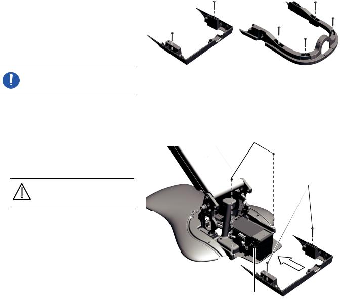
Install the Power Supply or Integrated Floor Box Cover Frames
A-dec 300 systems come with either a power supply cover or an integrated floor box cover.
NOTE The power supply cover frame ships attached to the power supply cover.
The steps for installing their frames are the same.
1.With the chair fully raised, use a 3/16" hex key to remove the two mounting screws from the chair base.
2.Attach the cover frame to the chair base with the two mounting screws.
CAUTION Never use a cover frame as a handle when moving the chair.
3.Attach the cover frame to the floor.
○If the floor is made of wood, use a Phillips head screwdriver and 1-1/4" size #10 screws.
○If it is a concrete floor, use a 1/4" masonry drill bit to make holes where the screws fit through the frame. Insert the plastic anchors in the holes then use a Phillips head screwdriver and 1-1/4" size #10 screws.
Install the Chair
Figure 8. Cover Frames
Power Supply Cover Frame |
Integrated Floor Box |
|
Cover Frame |
Figure 9. Install the Cover Frame
Attach Frame to
Chair Base
Attach Frame
to Floor
Mains On/Off Button
Power Supply
Cover Frame
86.0087.00 Rev E |
7 |
A-dec 300 System Installation Guide
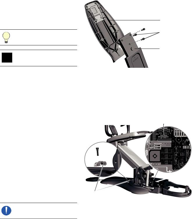
Install the Back Support
1.Use a 3/16" hex key to remove the 3 mounting screws from the back support.
2.Attach the back support to the chair back with the mounting screws.
TIP Start all three screws before tightening them.
CAUTION Be sure to tighten the screws firmly to avoid the back becoming loose during use.
Install the Footswitch (Optional)
If the system contains a footswitch, complete the following steps to install it.
1.From the rear of the chair, route the cord to the chair’s circuit board and connect it to the Touchpad Or Footswitch P5 connector on the chair circuit board.
2.Use a 3/16" hex key to secure the footswitch cord in one of the side holes of the strain relief.
NOTE If you are not installing any modules on to the chair, go to “Install Upholstery” on page 61.
Figure 10. Install the Back Support
Back Support
 Mounting Screws
Chair Back
Figure 11. Install the Footswitch
Touchpad Or Footswitch Connection
 Circuit Board
Strain
Relief
8 |
86.0087.00 Rev E |

I N S T A L L T H E
S U P P O R T C E N T E R
WARNING If the system includes a cuspidor, do not remove the positioning guide that is cable tied to the cuspidor bowl support until the support center is properly aligned. Complete the following section to ensure proper alignment of the support center.
You can mount the support center on either side of the chair. This section describes how to install the support center and connect the utilities.
Install the Chair-Base
Mount
NOTE If you have a post mount system, skip this procedure and follow the directions provided with the chair adaptor kit. Then go to “Install the Support Center Post” on the next page.
Use a 5/16" hex key driver and two 1-1/2" socket head screws to attach the chair-base mount to the side of the chair frame.
CAUTION Be sure to tighten the screws securely (approximately 30 ft-lb [4.15 m-kgs] of torque) so the mount does not loosen during use.
Install the Support Center
Tools Needed For This Section
5/16" hex key driver |
3/16" hex key |
Level |
Diagonal cutters |
Adjustable wrench |
Sleeve pusher |
|
|
Figure 12. A-dec 361 Support Center and Cuspidor
Figure 13. Install the Chair-Base Mount
Chair-Base Mount
Use a 5/16" hex key driver to apply
30 ft-lb (4.15 m-kgs) of torque pressure.
86.0087.00 Rev E |
9 |

A-dec 300 System Installation Guide
Install the Support Center
Post
1.Place the support center post in the chairbase mount with the notched bottom over the screw near the base of the mount.
NOTE If you have a post mount system, the support center post installs into a chair adaptor instead of the chair-base mount and the post does not have notches in the bottom.
WARNING If you’re installing a post mount system, anchoring the chair to the floor is required for mechanical stability. Failure to anchor properly could result in damage, serious injury, or death.
If the support center is installed to the left of the patient, face the square hole away from the chair. If the support center is installed to the right of the patient, face the square hole toward the chair.
2.Place a level vertically against the post and align it with the four leveling screws near the top of the chair-base mount.
NOTE If you have a post mount system on an A-dec 511 chair, the chair adaptor has eight leveling screws.
Figure 14. Install the Support Center Post
Notch
Square
Hole
One Set Of

 Leveling
Screws
10 |
86.0087.00 Rev E |
Install the Support Center
3.Use a 3/16" hex key to adjust the screws, switching from one set of leveling screws to the other until the post is level. Always align the level with the screws you are adjusting.
4.Once the post is level, evenly tighten the leveling screws to secure it.
NOTE This is the initial leveling of the post. The system requires a final level after everything is installed.
For final leveling instructions, see “Level the System” on page 77.
Install the Support Center Figure 15. Position the Support Center
1.Wrap the support center tubing bundle around your arm and lift the support center out of the box.
2.Remove the covers from the support center.
3.Place the support center over the support center post with the water bottle connection toward the toe of the chair.
CAUTION Be careful to clear all wires and tubing so they stay on the open side of the support center frame and do not get pinched or kinked.
4.Slide the support center down the post until its frame rests on the support screws on the support center post.
Support
Screw
86.0087.00 Rev E |
11 |
A-dec 300 System Installation Guide
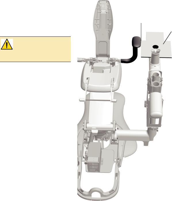
5.Align the support center depending on Figure 16. Ensure the Positioning Guide Clears the Armrest the configuration of the system:
○If you have an A-dec 300 system that includes a cuspidor, align the support center so the positioning guide clears the armrest. Use the jumper and test points to move the chair up and down when testing clearance.
WARNING The positioning guide must clear the armrest to provide the proper clearance of 1-1/8" (29 mm) between the cuspidor bowl and armrest.
○If you have a base mount system without a cuspidor, or a post mount system, align the support center so it is parallel to the dental chair.
Positioning guide must clear armrest.
Positioning Guide
12 |
86.0087.00 Rev E |

6.Use a 5/16" hex key driver to tighten the button-head screw. While tightening the screw, ensure the positioning guide retains its clearance of the armrest.
CAUTION To ensure that the button-head screw is properly tightened, use approximately 13 ft-lb. (1.8 m-kgs) of torque.
NOTE If you have a post mount system, you are finished installing the support center. Skip to the note after step 9 for instructions on routing tubing and wiring.
7.Use a 5/16" hex key driver to install each of the two 1-1/2" socket head screws until they are touching the back of the holes in the support center post.
8.Alternately tighten both socket head screws until they are firmly secure (use approximately 13 ft-lb.
[1.8 m-kgs] of torque). While tightening the screws, ensure the positioning guide retains its clearance of the armrest.
9.Route the support center tubing and wiring through the chair-base mount into the utilities area at the base of the chair.
NOTE If you are installing a post mount system, remove the Y-connector from the data line before routing the tubing. (The Y-connector is provided to connect to multiple data communication system devices.)
Route the tubing and wiring from the bottom of the support center through the convolute into the remote floor box.
If you are installing a post mount system on an A-dec 511 chair,
Install the Support Center
Figure 17. Secure the Support Center
Button Head Screw
Use a 5/16" hex key driver to apply 13 ft-lb (1.8 m-kgs) of torque pressure to the screws.
Install two 1-1/2" Socket Head Screws.
Figure 18. Route the Support Center Tubing Bundle
Utilities Area
Chair-Base Mount
86.0087.00 Rev E |
13 |

A-dec 300 System Installation Guide
separate the power cables and data line from the tubing group and route them from the support center, underneath the mount, and down the lift arm to the power supply. Route the rest of the tubing bundle through the convolute into the remote floor box.
For information about installing the remote floor box, see “Install the Remote Floor Box” on
page 39.
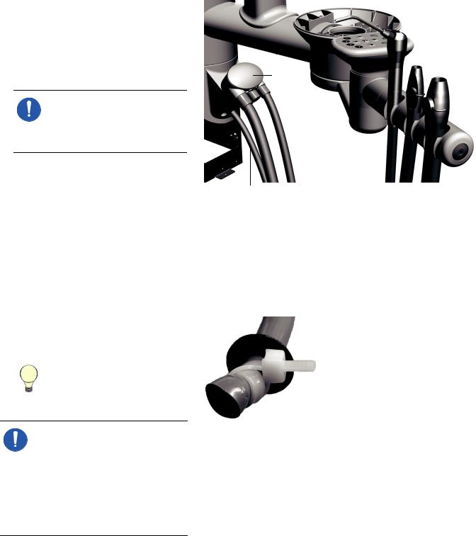
CAUTION Once you’ve completed installing the support center, verify that the end of the cuspidor ventilation tube is 1/2" (13 mm) above the support center frame. This ensures that the cuspidor drains properly.
Install the Moisture
Separator (Optional)
To install the moisture separator, use the directions included in the moisture separator kit (p/n 41.1477.00); then see “Connect the Utilities” on page 40.
Figure 19. Verify the Cuspidor Ventilation Tubing Position
Support
Center
Frame 1/2" (13mm) 

Cuspidor
Ventilation Tube
14 |
86.0087.00 Rev E |

Install the Assistant's Instrumentation
I N S T A L L T H E
A S S I S T A N T ' S
I N S T R U M E N T A T I O N
Figure 20. Assistant’s Instrumentation
Assistant’s instrumentation can be mounted three ways.
Radius®-Style (351) . . . . . . . . . . . . . 16
Cuspidor-Mounted (353) . . . . . . . . . . 18
Telescoping (352) . . . . . . . . . . . . . . 20
A-dec 351 Radius-Style
Assistant’s Instrumentation
with Touchpad
A-dec 352 Telescoping |
A-dec 353 |
Assistant’s Instrumentation |
Cuspidor-Mounted |
with Optional Touchpad |
Assistant’s Instrumentation |
|
with Optional Touchpad |
86.0087.00 Rev E |
15 |

A-dec 300 System Installation Guide
Install a Radius-Style
Assistant’s
Instrumentation (351)
Tools Needed For This Section
Hex key set
Figure 21. Types of Washers Used
Install the Assistant’s
Instrumentation Arm
1.Slide the bearing and two washers from the kit onto the screw.
2.Insert the screw through the hole in the assistant’s instrumentation arm.
3.Slide the Nylatron® washer onto the screw.
4.Put Loctite® on the end of the screw.
5.Use a 1/4" hex key to securely tighten the arm to the chair. The arm should rotate smoothly and not drift.
6.Place the syringe in its holder on the assistant’s instrumentation.
7.Place the high volume evacuation (HVE) and saliva ejector in their holders; then attach their tubing to the vacuum canister.
Nylatron Washer |
Flat Washer |
Bearing |
Figure 22. Install the Assistant’s Instrumentation Arm
Nylatron Washer
Assistant’s
 Instrumentation Arm
 Flat Washer
Bearing
Flat Washer
 Screw
Screw
16 |
86.0087.00 Rev E |

Install the Assistant's Instrumentation
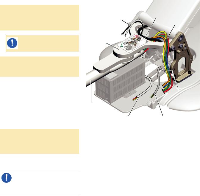
Route the Tubing, Cables, and
Lines
1.From the back of the chair, route the vacuum line to the left of the lift cylinder and above the clear hydraulic tubing.
2.Route the tubing, power cables, and data line to the right of the lift cylinder and above the overflow bottle.
3.Use a 3/16" hex key to loosen the socket head screw securing the middle white mounting block.
4.Remove the top screw and mounting block.
5.Slide the notch in the plate between the middle mounting block and the lift arm.
6.Replace the top screw and mounting block. Make sure the screw is securely tightened.
7.Tighten the middle socket head screw.
Figure 23. Install the Assistant’s Instrumentation Plate
Top
Mount
Screw
Plate
Notch
Loosen
Middle
Screw
Tubing
and
Vacuum Cables
Line
Clear |
|
|
|
Overflow |
|
|
|
Bottle |
|
|
|
|||
Hydraulic |
|
|||
|
|
|||
Line |
|
|
||
8. Cable tie the tubing, power cables, and |
Figure 24. Cable Tie the Tubing and Wires |
data line to the bottom two mounting |
|
blocks. |
|
9.Route the syringe tubing between the motor pump and the wire cover, then behind the power supply.
10.Route the power cables and data line to the chair circuit board.
NOTE If the system does not include other modules, go to “Install the Contoured Floor Box” on
page 37.
Cable Tie to These Blocks
86.0087.00 Rev E |
17 |

A-dec 300 System Installation Guide
Install a
Cuspidor-Mounted
Assistant’s
Instrumentation (353)
1.Use diagonal cutters to cut the cable tie and remove the positioning guide.
NOTE Save the positioning guide and the foam plug holding it in the cuspidor bowl support. You will need it later to verify proper clearance between the cuspidor bowl and armrest. For more information, see “Verify Proper Clearance Between the Cuspidor Bowl and the Armrest” on page 94.
2.If the system includes an AVS, use a 1/8" hex key to remove the two screws connecting the toggle assembly to the bottom of the cuspidor bowl support.
3.If the assistant's instrumentation includes a touchpad, route the power cable and data line up through the cuspidor holder. For the wires to fit properly, place the power cable into the grooves first then the data line.
4.Place the assistant's instrumentation under the cuspidor holder and angle it away from the chair so that the post fits into the hole in the bottom of the cuspidor bowl support.
5.To attach the assistant’s instrumentation to the bottom of the cuspidor holder, use a 3/16" hex key to install the 1/4-20 x 1" screw in the middle and a 5/32" hex key to install the 10-32 x 5/8" screw in the large recessed hole that is off center.
6.If you disconnected the AVS toggle assembly in step 2, reconnect it now.
|
Tools Needed For This Section |
|
|
Diagonal cutters |
Sleeve pusher |
Hex key set |
|
|
|
Figure 25. Routing with a Touchpad Viewed From Below
 Data
Data
Ports
WAGO
Connectors
Figure 26. Routing with a Touchpad Viewed From Above
Data Line and Power Cable Fit in Cuspidor Grooves
Figure 27. Socket Head Screws (Actual Size Shown)
1/4-20 x 1" - Goes in |
10-32 x 5/8" - Goes in |
the Middle Hole |
the Recessed Hole |
18 |
86.0087.00 Rev E |
Install the Assistant's Instrumentation
7.If the system includes a touchpad, route Figure 28. Route the HVE, Saliva Ejector, and Syringe Tubing the data line and power cable through
the support center (see Figure 25 on page 18).
8.Place the high volume evacuation (HVE) and saliva ejector in their holders; then
attach their tubing to the vacuum canister.
NOTE If the system includes an AVS, the HVE and saliva ejector are installed before the product is shipped and cannot be removed.
9.Place the syringe in the holder and route its tubing under the vacuum canister through the center hole.
Vacuum
Canister
Syringe
Tubing
10.Use a cable tie and a washer to create a |
Figure 29. Install the Strain Relief for the Assistant’s Syringe |
|
|
strain relief for the syringe tubing. Make |
|
|
a double loop with the cable tie to firmly |
|
|
hold the tubing. |
|
|
|
|
|
TIP When setting the strain |
|
|
relief, leave enough tubing to |
|
|
match the drape of the |
|
|
instrument tubing. |
|
|
|
|
NOTE If the system does not include other modules, go to the section for the system’s configuration:
•Base Mount System - “Install the Contoured Floor Box” on
page 37
•Post Mount System - “Install the Remote Floor Box” on page 39
86.0087.00 Rev E |
19 |

A-dec 300 System Installation Guide
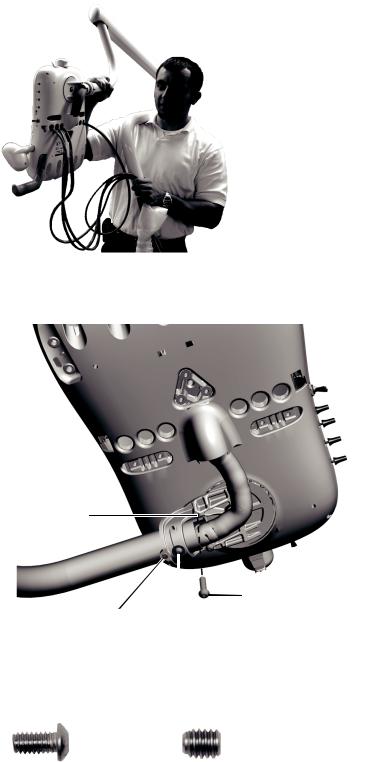
Install an Assistant’s Instrumentation Mounted on a Telescoping Arm (352)
1.Use a 3/16" hex key and three 1" socket head screws to mount the hub for the telescoping arm on the support center. The stop on the hub goes toward the toe of the chair.
2.Push the sheath onto the barb on the bottom of the assistant’s holder assembly.
3.Set the assistant’s arm on the hub.
4.Push down one end of the wave washer and catch it on the hub ridge. Continue to work systematically around the hub to push the washer down until it is completely installed.
5.Place the HVE and saliva ejector in their holders; then attach their tubing to the vacuum canister.
6.If the system includes a touchpad:
(1)Route the touchpad tubing under the vacuum canister through the hole on the right (it is the largest hole).
(2)Install the strain relief by placing the washer on the tubing then inserting the bushing into the tube.
TIP When setting the strain relief, leave enough tubing to match the drape of the instrument tubing.
|
Tools Needed For This Section |
|
|
3/16" hex key |
Sleeve pusher |
Diagonal cutters |
|
|
|
Figure 30. Install the Telescoping Arm Hub
 Toe of the Chair
Stop
Figure 31. Install the Telescoping Arm
Wave Washer
Assistant’s
Holder
Assembly
Sheath
Figure 32. Install the Strain Relief for the Touchpad Tubing
20 |
86.0087.00 Rev E |
Install the Assistant's Instrumentation
(3)Route the data line and power cables Figure 33. Route the Data Line and Power Cables through the support center.
7.Place the syringe in the holder and route its tubing under the vacuum canister through the center hole (see Figure 31 on page 20).
8.Use a cable tie and a washer to create a strain relief for the syringe tubing. Make a double loop with the cable tie to firmly hold the tubing.
TIP When setting the strain relief, leave enough tubing to match the drape of the instrument tubing.
NOTE If the system does not include other modules, go to the section for the system’s configuration:
•Base Mount System - “Install the Contoured Floor Box” on
page 37
•Post Mount System - “Install the Remote Floor Box” on page 39
WAGO
Connectors
Figure 34. Route the Syringe Tubing
Syringe
Tubing
Figure 35. Install the Strain Relief for the Assistant’s Syringe
86.0087.00 Rev E |
21 |
A-dec 300 System Installation Guide
I N S T A L L T H E
D E L I V E R Y S Y S T E M
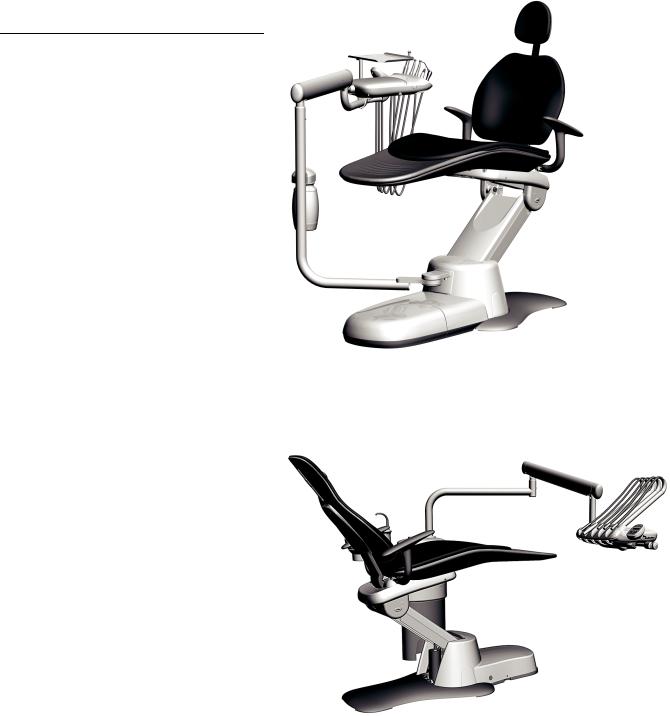
Figure 36. Delivery Systems
The A-dec 300 system can be configured with a Traditional or Continental delivery system. The installation steps are the same for both of them.
Delivery systems can be Radius-style or mounted on a support center.
Radius-Style (332 & 333) . . . . . . . . . . 23
Support Center Mounted (354 & 335) . 29
A-dec 332 Radius-Style Traditional Delivery System
A-dec 335 Continental Delivery System
mounted on a Support Center
22 |
86.0087.00 Rev E |
Install a Radius-Style Delivery System (332 & 333)
Install the Rigid Arm
1.Raise the chair all the way up.
2.Turn off the power.
Install the Delivery System
|
Tools Needed For This Section |
|
|
Hex key set |
Diagonal cutters |
Sleeve pusher |
Adjustable wrench |
Tape measure |
|
|
|
Figure 37. Prepare the Chair Tower
3. Cut the cable tie holding the clear hydraulic tubing that goes from the lift cylinder to the motor pump.
4. Push the tubing back so that it is behind the post on the chair tower.
Post
 Cable
Cable
Tie
Clear Tubing
86.0087.00 Rev E |
23 |

A-dec 300 System Installation Guide
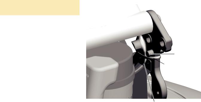
5.Place the notches in the front mount casting over the posts on the chair towers.
CAUTION Make sure all tubing and wiring are away from the posts so they do not get pinched.
6.While holding the rigid arm in place, install the front bolt then the back bolt on one side and finger tighten.
7.Install the bolts on the other side; then use a 5/16" hex key to securely tighten all bolts.
Figure 38. Install the Rigid Arm
Front Mount Casting
|
|
|
|
Mount Bolts |
|
|
|
|
|
|
|
|
|
|
|
|
|
Post |
|
|
|
|
|
|
Chair |
Notches |
Clear Hydraulic Tubing |
||
Tower |
|
Positioned Between the Post |
||
|
|
|
and Axle for the Link Arm |
|
24 |
86.0087.00 Rev E |
Install the Water Bottle
1.Use a 1/8" hex key to loosen the screw below the hole in the rigid arm.
2.Route the water bottle tubing into the hole, through the arm and out the bottom.
3.Slide the water bottle housing down over the mount screw and secure it to the arm.
Install the Delivery System
Figure 39. Install the Water Bottle
Water Bottle |
|
|
|
|
Housing |
Rigid Arm |
|||
|
|
|||
|
|
Hole |
||
|
|
|
|
|
|
|
|
|
|
Install the Flexarm and Control
Head
1.Cut the cable tie holding the trim ring to the delivery system tubing bundle.
2.Remove the delivery system from the box and balance it over your shoulder, with the control head in back of you, so one hand is free to route the tubing bundle.
3.Route the delivery system tubing bundle down through the rigid arm.
TIP To keep Traditional delivery system handpiece tubing out of the way, wrap them around the control head before installing the flexarm.
4.Insert the flex arm into the rigid arm until it is fully seated.
Mount Screw
Figure 40. Install the Flexarm
Flexarm
Trim Ring
Rigid Arm
 Tubing Bundle
86.0087.00 Rev E |
25 |

A-dec 300 System Installation Guide
5.Use a 5/32" hex key to loosen the button-head screw that holds the control head’s position.
6.Rotate the control head so it is positioned over the hole for the missing leveling screw.
7.To hold the control head in place, use a 5/32" hex key to install and tighten the 1/4-20 x 1/2" leveling screw.
8.Use a 5/32" hex key to install the 3/8" setscrew.
9.Place the handpiece tubing in their holders and insert the adjustment keys into their holes on the side of the control head.
NOTE If you are installing a Continental delivery system, insert the whip hooks into the whips. The top ends of the whip hooks face the front of the control head.
Figure 41. Install the Control Head
Hole for Missing
Leveling Screw
Install 3/8" |
|
|
Loosen |
||
Setscrew |
Button Head |
|
|
Screw |
|
Install and Tighten 1/4-20 x 1/2" Leveling Screw
Figure 42. Leveling and Setscrews (Actual Size Shown)
1/4-20 x 1/2" |
5/16-18 x 3/8" |
Leveling Screw |
Setscrew |
Figure 43. Insert Whip Hooks and Adjustment Keys
Whip Hook
Adjustment Key
26 |
86.0087.00 Rev E |
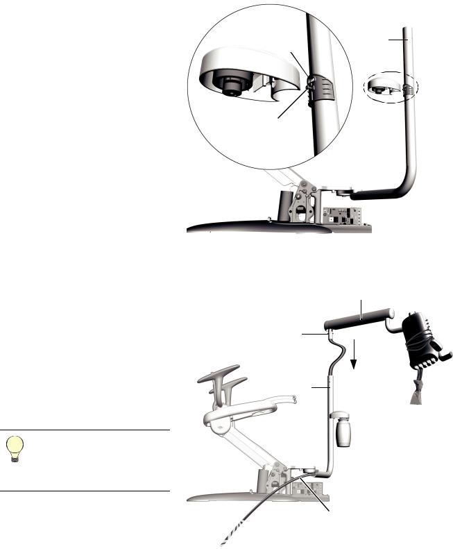
Route the Tubing and Wiring
1.From the back of the chair, route the foot control tubing over the strain relief and behind the power supply.
2.Measure three feet of the water bottle tubing from where it comes out of the rigid arm. Cut off the excess.
3.Strip the sheath around the water bottle tubing back to the rigid arm.
TIP Mark the ends of the water bottle tubing to distinguish them from the delivery system tubing when connecting the utilities.
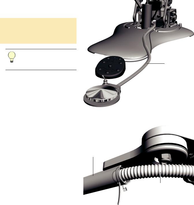
4.Route both the water bottle and delivery system tubing bundles through the convolute (see Figure 45).
5.Form a loop with a cable tie through the two holes in the rigid arm.
6.Push the convolute about an inch (a few centimeters) through the loop into the rigid arm.
7.Tighten the cable tie to secure the convolute.
Install the Delivery System
Figure 44. Route the Foot Control Tubing
Tubing Ridges
Face Up
Figure 45. Route the Tubing Bundles Through the Convolute
Front Mount Casting 
Rigid Arm
Convolute
 Secure with Cable Tie
86.0087.00 Rev E |
27 |
A-dec 300 System Installation Guide
8.Remove the tape from the ends of the water bottle and delivery system tubing.
9.Route the water bottle and delivery system tubing up through the front mount (be sure to go behind the black hydraulic tubing) then down to behind the power supply.
NOTE Improper routing of the tubing can hinder the movement of the delivery system rigid arm.
10.Route the delivery system power cables, ground wire, and data line up through the front mount and down to the chair circuit board on the power supply.
11.If the system includes an assistant’s instrumentation, route its syringe tubing around the lift cylinder to behind the power supply.
Arrange the Tubing
1.Position the rigid arm so that it is straight out from the middle of the chair, in line with the front mount.
2.Neatly gather the tubing. Cable tie it to the chair tower.
NOTE If the system includes a tray holder, see “Install the Tray Holder (Optional)” on page 32. If not, go to “Install the Contoured Floor Box” on page 37.
Figure 46. Route the Tubing and Wires |
|
||
|
|
Water |
|
|
Hydraulic |
Bottle and |
|
Power Cables |
Delivery |
||
Tubing |
System |
||
and Data Line |
|||
|
Tubing |
||
|
|
||
Front Mount
Cable Tie
Rigid Arm
Straight Out
Assistant’s Syringe |
Foot Control |
Tubing |
Tubing |
28 |
86.0087.00 Rev E |

Install a Delivery System Mounted on a Support Center (334 & 335)
Install the Components
1.Lower the chair. Turn off the power.
2.Ensure the correct trim ring is on the delivery system post.
○If the system includes a delivery system but no assistant’s instrumentation mounted on a telescoping arm, use the top trim ring in Figure 47.
○If the system includes a delivery system and assistant’s instrumentation mounted on a telescoping arm, use the bottom trim ring in Figure 47.
Install the Delivery System
|
Tools Needed For This Section |
|
|
Hex key set |
Diagonal cutters |
Adjustable wrench |
Sleeve pusher |
|
|
Figure 47. Delivery System Post Trim Rings
This trim ring ships on the delivery system post.
Trim Ring Used With Delivery System
This trim ring ships in the assistant’s instrumentation box.
Trim Ring Used With Delivery System and
Assistant’s Instrumentation Mounted on a
Telescoping Arm
86.0087.00 Rev E |
29 |
A-dec 300 System Installation Guide |
|
3. Remove the delivery system from the |
Figure 48. Carry the Delivery System |
box and balance it over your shoulder so |
|
one hand is free to route the tubing |
|
bundle. |
|
The delivery system post inserts into the |
|
support center in the post hole toward |
|
the toe of the chair. |
|
4.Route the tubing bundle into the support center then insert the delivery system post into the support center until it is fully seated.
Figure 49. Install the Control Head
5.Use a 5/32" hex key to loosen the button-head screw that holds the control head’s position.
6.Rotate the control head so it is positioned over the hole for the missing leveling screw.
Hole For Missing
Leveling Screw
Install 3/8" |
|
|
Loosen |
||
Setscrew |
Button Head |
|
|
Screw |
|
Install and Tighten 1/4-20 x 1/2" Leveling Screw
7.To hold the control head in place, use a 5/32" hex key to install and tighten the 1/4-20 x 1/2" leveling screw.
8.Use a 5/32" hex key to install the 3/8" setscrew.
Figure 50. Leveling and Setscrews (Actual Size Shown)
1/4-20 x 1/2" |
3/8" |
Leveling Screw |
Setscrew |
30 |
86.0087.00 Rev E |
Loading...