


 Owner's

 Guide
Guide


CASCADE®
HANDPIECE
DELIVERY
SYSTEM
® |
85.2639.00 |
|
Warranty Information
Serial Number
Model Number
Date Purchased
Date of |
Technician's |
Service Model/Description of Service |
Initials |
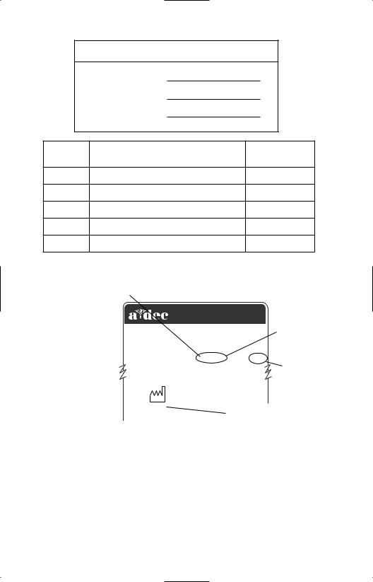
ALPHABETICAL EQUIVALENT
TO THE NUMERAL OF THE
MONTH MANUFACTURED
A |
January |
2601 CRESTVIEW DRIVE |
|
||
B |
February |
|
|||
NEWBERG, OREGON 97132 USA |
SERIAL |
||||
C |
March |
Designated EU Representative: A-dec Dental U.K., Ltd. |
|||
D |
April |
Austin House, 11 Liberty Way, Attleborough Fields, |
NUMBER |
||
Nuneaton, Warwickshire, England CV116RZ |
|
||||
|
|
|
|||
E |
May |
|
|||
Tele: (44) 24 7635 0901 |
|
||||
F |
June |
SN: J828287 REF: 2122 |
MODEL |
||
|
|
||||
G |
July |
|
|
||
|
|
NUMBER |
|||
H |
August |
MADE |
|||
|
|||||
|
|
|
|||
I |
September |
IN USA |
|
||
J |
October |
1999 |
|
|
|
|
|
|
|
|
|
K |
November |
|
YEAR MANUFACTURED |
||
L |
December |
|
|||
|
|
|
|||
|
|
|
|||
|
|
|
|
|
|
Serial Number Identification
Serial Number Location:
• Located on the underside of the control head.
For service information contact your authorized A-dec dealer.
Check with local codes and A.D.A. (Americans with Disabilities Act) requirements for installation of this product.


 Warranty
A-dec warrants its products and A-dec/W&H Synea handpieces against defects in material or workmanship for one year from time of delivery. All other handpiece instrumentation has a warranty period of six months. A-dec’s sole obligation under the warranty is to provide parts for the repair, or at its option, to provide the replacement product (excluding labor). The buyer shall have no other remedy. (All special, incidental, and coincidental damages are excluded.) Written notice of breach of warranty must be given to A-dec within the warranty period. The warranty does not cover damage resulting from improper installation or maintenance, accident or misuse.The warranty does not cover damage resulting from the use of cleaning, disinfecting or sterilization chemicals and processes. The warranty also does not cover light bulbs. Failure to follow instructions provided in A-dec’s Operation and Maintenance Instructions (Owner’s Guide) may void the warranty.
NO OTHER WARRANTIES AS TO
MERCHANTABILITY OR OTHERWISE ARE MADE.

 ®
®
All product names used in this document are trademarks or
registered trademarks of their respective holders.
Printed in U.S.A. • Copyright © 1999 • All Rights Reserved

 Cascade Handpiece
 Delivery
 System


This Owner’s Guide includes both styles of Cascade Handpiece Delivery System, Continental and Traditional. Uses and adjustments are the same for both, except where noted.
Cascade Handpiece Delivery System
(Traditional-style Control Head with Unitized Holders)
Cascade Handpiece Delivery System
(Continental®-style Control Head with touch pad and push button arm brake)


 Cascade Handpiece Delivery System
Serial number location, service information, and warranty information are located on the inside front cover and front page.
CONTENTS
Cascade Handpiece Delivery System............ |
2 |
Handpiece Actuation .................................... |
2 |
Drive Air Pressure Gauge.............................. |
2 |
Arm Brake (Chair-Mounted Delivery Systems Only).... 3 |
|
Foot Control .................................................. |
3 |
Handpiece Controls ...................................... |
4 |
Master On/Off Toggle.............................. |
4 |
Drive Air Pressure Controls ..................... |
5 |
Coolant Air Flow Control ........................ |
6 |
Coolant Water Flow Controls.................. |
7 |
Handpiece Tubing Flush ......................... |
8 |
Handpiece Dry Block Conversion................. |
9 |
Oil Collector ................................................ |
10 |
Continental-Style Control Head |
|
Handpiece Whip Adjustment ............... |
10 |
Traditional-Style Control Head |
|
Holder Adjustments............................... |
11 |
Touch Pad (Optional) ................................... |
11 |
Tray Holder (Optional) ................................. |
12 |
Tray Holder/Tray Arm |
|
Tension Adjustment .......................... |
13 |
Autoclavable Syringe.................................. |
14 |
System Air And Water |
|
Pressure Adjustment.............................. |
14 |
Care Instructions......................................... |
14 |
Flexible Arm................................................ |
15 |
Counterbalance Spring Adjustment ..... |
15 |
Arm Stop Adjustment |
|
for Left/Right Conversion.................. |
18 |
Continental-Style Control Positioning........ |
19 |
Trans-Thorax Positioning...................... |
19 |
Maintenance ............................................... |
20 |
Adjustments and Specifications.................. |
20 |
Identification of Symbols ............................ |
22 |
Classification of Equipment (EN 60601-1) ... |
22 |
1

 Cascade Handpiece
 Delivery
 System


Cascade Handpiece Delivery System
Your Cascade Handpiece Delivery System is built around A-dec’s proven Century Plus® control blocks for three handpieces and, in most instances, A-dec’s Autoclavable Syringe.
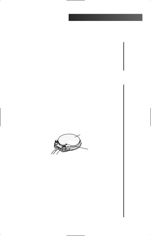
Handpiece Actuation
Handpiece actuation is automatic. When you lift a handpiece from its holder, or pull the Continentalstyle whip forward, the handpiece becomes active and will run when you press on the foot control disc (refer to page 3). Return the handpiece to its resting position to deactivate it.
Figure 1. Handpiece Actuation
Drive Air Pressure Gauge
The drive air pressure gauge (see Figure 2) indicates, in psi and kg/cm2, the drive air pressure to the active handpiece.
HANDLE WITH PUSH BUTTON ARM BRAKE
DRIVE AIR
 PRESSURE GAUGE
Figure 2. Drive Air Pressure Gauge
2


 Cascade Handpiece Delivery System
Arm Brake
(Chair-Mounted Delivery Systems Only)
The arm is braked against vertical movement until you press the arm brake button (see Figure 2 on page 2). You then are able to position the control head. Releasing the arm brake button locks the control head in place
Foot Control
The foot control modulates drive air to the active handpiece and provides an air signal that activates the coolant air and coolant water flow. The foot control is operated by light foot pressure applied to any part of the foot control disc.
The foot control is equipped with a wet/dry toggle and can be equipped with an optional chip blower button (see Figure 3).
FOOT CONTROL DISC
CHIP BLOWER BUTTON 
(Optional)
WET/DRY
TOGGLE
BLUE DOT (water ON)
Figure 3. Foot Control
Wet/Dry Toggle. Allows you to shut off the coolant water to the handpiece without moving your hands from the oral cavity. Using your foot, move the toggle away from the blue dot to turn the coolant water OFF. Move the toggle toward the blue dot to turn the coolant water ON.
Chip Blower Button. Sends a jet of air through the handpiece when it is not running.
3
 Cascade Handpiece
 Delivery
 System


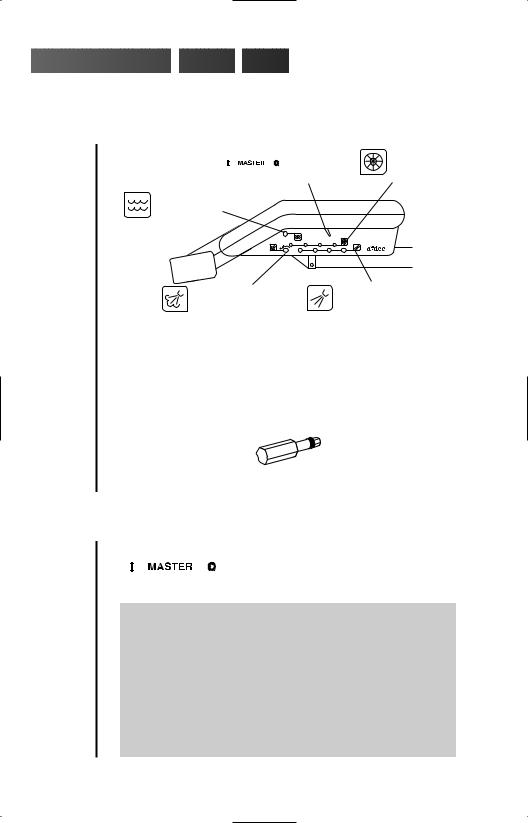
Handpiece Controls
MASTER |
|
DRIVE AIR |
ON/OFF |
|
PRESSURE |
TOGGLE |
|
CONTROLS |
HANDPIECE |
|
(see page 5) |
FLUSH CONTROL |
|
|
(see page 8) |
|
|
PUSH |
O |
|
I MASTER |
|
|
1 2 3 |
4 |
® |
COOLANT AIR |
COOLANT WATER |
|
FLOW CONTROLS |
||
FLOW CONTROL |
||
(see page 7) |
||
(see page 6) |
||
|
Figure 4. Handpiece Controls
Adjustment keys are provided for making adjustments to the recessed controls. You can order additional or replacement keys from your authorized A-dec dealer or use a 1⁄8" hex key.
Figure 5. Autoclavable Adjustment Key
Master On/Off Toggle
The master on/off toggle
(see Figure 4) turns air, water, and electricity on or off to the system.
CAUTION
The MASTER ON/OFF TOGGLE should be in the
OFF (0) position whenever the unit is not in use.
This will prevent the possibility of water damage should a leak occur while the unit is unattended.
Making sure the unit is off will also prevent the possibility of self-activation and the resulting burn-out of your electrical accessories.
4


 Cascade Handpiece Delivery System
Drive Air Pressure Controls
The drive air pressure controls (see Figure 4 on page 4) are used to adjust the drive air pressure to each handpiece.
Adjust the drive air pressure to meet the handpiece manufacturer’s dynamic drive air pressure specification. Refer to the documentation that came with your handpiece for the dynamic drive air pressure specification.
You will need a 3⁄32" hex key to complete this adjustment.
1.Install a bur in the handpiece.
2.Locate the drive air gauge on the front of the control head (see Figure 2 on page 2).
3.Move the wet/dry toggle on the foot control
(see Figure 3 on page 3) to the OFF position, away from the blue dot).
4.Turn the drive air control clockwise until the valve seats.
5.Fully depress the foot control disc.
6.While running the handpiece, watch the drive air gauge and adjust the handpiece dynamic drive air pressure to meet manufacturer’s specifications.
•Turn the drive air control counterclockwise to increase drive air pressure flow.
•Turn the control clockwise to decrease flow.
NOTE
Do not turn the control counterclockwise beyond the point where the drive air pressure no longer increases. The control adjustment screw may come completely out of the unit.
7. Repeat steps 1 through 6 for EACH handpiece.
5
 Loading...