


 Loading...
A-dec 200™ Service Guide
A - D E C 2 0 0 S E R V I C E G U I D E
Copyright
© 2011 A-dec Inc. All rights reserved.
A-dec Inc. makes no warranty of any kind with regard to this material, including, but not limited to, the implied warranties of merchantability and fitness for a particular purpose. A-dec Inc. shall not be held liable for any errors contained herein or any consequential or other damages concerning the furnishing, performance or use of this material. The information in this document is subject to change without notice. If you find any problems in the documentation, please report them to us in writing. A-dec Inc. does not warrant that this document is error-free.
No part of this document may be copied, reproduced, altered, or transmitted in any form or by any means, electronic or mechanical, including photocopying, recording, or by any information storage and retrieval system, without prior written permission from A-dec Inc.
Trademarks and Additional Intellectual Property Rights
A-dec, the A-dec logo, A-dec 500, A-dec 300, Cascade, Cascade Master Series, Century Plus, Continental, Decade, ICX, ICV, Performer, Preference, Preference Collection, Preference ICC, and Radius are trademarks of A-dec Inc. and are registered in the U.S. and other countries. A-dec 200, Preference Slimline, and reliablecreativesolutions are also trademarks of A-dec Inc. None of the trademarks or trade names in this document may be reproduced, copied, or manipulated in any manner without the express, written approval of the trademark owner.
Certain touchpad symbols are proprietary to A-dec Inc. Any use of these symbols, in whole or in part, without the express written consent of A-dec Inc. is strictly prohibited.
Intended Application and Use
This equipment/system is intended for diagnostic and therapeutic treatment of dental patients by licensed health care professionals.
A dental operative unit (with or without accessories) is an AC-powered device intended to supply power to and serve as a base for other dental devices, such as a dental handpiece, a dental operating light, an air or water syringe unit, an oral cavity evacuator, a suction operative unit, and other dental devices and accessories.
Comments and Feedback
If you have any feedback or comments about this document, contact:
A-dec Inc.
Technical Communications Department
2601 Crestview Drive
Newberg OR 97132 USA
USA/Canada: 1.800.547.1883
Worldwide: 1.503.538.7478
E-mail: techcomm@a-dec.com
Website: www.a-dec.com
Regulatory Information
Regulatory information is provided with A-dec equipment as mandated by agency requirements. This information is delivered in the equipment’s Instructions for Use or the separate Regulatory Information and Specifications document. If you need this information, please go to the Document Library at www.a-dec.com.
Product Service
For service information, contact your local authorized A-dec dealer. To find your local dealer, go to www.a-dec.com.

C O N T E N T S
1 INTRODUCTION ............................................... |
1 |
Get Support ............................................................ |
1 |
International Customer Service ......................................... |
1 |
Inside this Guide ...................................................... |
1 |
A-dec 200 System ..................................................... |
2 |
Serial and Model Numbers........................................... |
3 |
Service Tools ........................................................... |
4 |
2 DENTAL CHAIR ................................................ |
7 |
Product Overview..................................................... |
8 |
Chair Load Capacity....................................................... |
8 |
Power and Status ......................................................... |
8 |
Limit Switch and Chair Lockout ......................................... |
8 |
Circuit Board Components ............................................... |
9 |
Service, Maintenance, and Adjustments ....................... |
10 |
Factory Default Routine ................................................ |
10 |
Potentiometers .......................................................... |
11 |
Adjust the Base Up Limit Switch: ........................................ |
11 |
Adjust the Base Positioning Potentiometer ............................ |
12 |
Adjust the Back Potentiometer .......................................... |
12 |
Hydraulic System ........................................................ |
13 |
Solenoids.................................................................. |
14 |
Test the Solenoid ........................................................... |
14 |
Remove and Replace the Solenoid ....................................... |
14 |
Test the Motor Pump.................................................... |
15 |
Headrest Adjustments .................................................. |
16 |
Chair Speed Adjustments .............................................. |
16 |
Illustrated Parts Breakdown....................................... |
17 |
Part Identification....................................................... |
17 |
Chair Covers.............................................................. |
17 |
Upper Chair Assembly .................................................. |
18 |
Mid Chair Assembly ..................................................... |
20 |
Lower Chair Assembly................................................... |
22 |
Headrest Assembly ...................................................... |
23 |
Motor Pump and Capacitor Assembly ................................. |
24 |
Hydraulic Manifold Assembly .......................................... |
26 |
Hydraulic Tank Assembly ............................................... |
27 |
Base Limit Switch Assembly............................................ |
27 |
Back Potentiometer Assembly ......................................... |
28 |
Base Position Potentiometer Assembly ............................... |
29 |
3 PROGRAMMING .............................................. |
31 |
Touchpad Options ................................................... |
32 |
Chair Positions ........................................................... |
32 |
X-Ray/Rinse Button...................................................... |
32 |
Dental Light .............................................................. |
33 |
Auto On/Off ................................................................. |
33 |
Cuspidor Cupfill and Bowl Rinse....................................... |
34 |
Standard Cuspidor (no touchpad) ....................................... |
34 |
Cuspidor with Optional Touchpad ....................................... |
34 |
Customize Cupfill and Bowl Rinse Functions .......................... |
34 |
4 DELIVERY SYSTEM .......................................... |
35 |
Product Overview................................................... |
35 |
A-dec Tubing.............................................................. |
36 |
Service, Maintenance, and Adjustments ....................... |
37 |
Flexarm Adjustments ................................................... |
37 |
Instrument Holder Adjustments ....................................... |
38 |
Handle ....................................................................... |
38 |
Control Block ............................................................. |
39 |
Remove the Control Block ................................................ |
39 |
Handpiece Control Adjustments....................................... |
40 |
Adjust the Water Coolant ................................................. |
40 |
Adjust the Air Coolant .................................................... |
40 |
Adjust the Drive Air Pressure ............................................. |
41 |
Oil Collector .............................................................. |
41 |
86.0016.00 Rev A |
iii |
A-dec 200 Service Guide
Handpiece Tubing Replacement....................................... |
42 |
Adjust Tubing Length ...................................................... |
42 |
Quad Voltage Intraoral Light Source (QVIOLS)...................... |
43 |
Intraoral Light Source Adjustments ..................................... |
44 |
Intraoral Light Source Length and Voltage .......................... |
45 |
Illustrated Parts Breakdown ...................................... |
47 |
Part Identification....................................................... |
47 |
A-dec 200 Delivery System............................................. |
48 |
Holder Assembly......................................................... |
50 |
Control Block Assembly ................................................ |
52 |
Toggles Assemblies (Flush Toggle and Master On/Off Toggle) .... |
53 |
Oil Collector ............................................................. |
54 |
5 CUSPIDOR AND SUPPORT CENTER ....................... |
55 |
Product Overview................................................... |
55 |
Service, Maintenance, and Adjustments ....................... |
56 |
Bowl Rinse Flow Adjustment .......................................... |
56 |
Adjusting the Cuspidor Cupfill and Bowl Rinse ........................ |
56 |
Self-Contained Water System ......................................... |
56 |
Illustrated Parts Breakdown ...................................... |
57 |
Part Identification....................................................... |
57 |
A-dec 200 Support Center ............................................. |
58 |
A-dec 200 Cuspidor ..................................................... |
60 |
Self-Contained Water Bottle .......................................... |
61 |
Cupfill/Bowl Rinse Manifold ........................................... |
62 |
6 ASSISTANT’S INSTRUMENTATION ........................ |
63 |
Product Overview................................................... |
63 |
Service, Maintenance, and Adjustments ....................... |
64 |
Auto-air Holder .......................................................... |
64 |
Positioning Assistant’s Holder ......................................... |
64 |
Assistant’s Touchpad Connections .................................... |
65 |
Vacuum Instrumentation ............................................... |
65 |
Solids Collector .......................................................... |
66 |
Illustrated Parts Breakdown ...................................... |
67 |
Part Identification ....................................................... |
67 |
Telescoping Assistant’s Arm............................................ |
68 |
Assistant’s Touchpad Assembly ........................................ |
69 |
Assistant’s Auto-Air Holder............................................. |
70 |
Assistant’s Standard Holder ............................................ |
72 |
7 UTILITIES ..................................................... |
73 |
Product Overview................................................... |
74 |
Shutoff Valves ............................................................ |
74 |
Gauge and Pre-Regulator ................................................. |
74 |
Service, Maintenance, and Adjustments ....................... |
75 |
Air and Water Filter Replacement .................................... |
75 |
Illustrated Parts Breakdown ...................................... |
77 |
Part Identification ....................................................... |
77 |
Air Filter/Regulator Assembly ......................................... |
78 |
Water Filter/Regulator Body Assembly............................... |
79 |
8 DENTAL LIGHT............................................... |
81 |
Product Overview................................................... |
82 |
Dental Light Specifications ............................................ |
82 |
Nominal Light Intensity ................................................... |
82 |
On/Off Button .............................................................. |
82 |
Auto On/Off Feature ...................................................... |
82 |
Service, Maintenance, and Adjustments ....................... |
83 |
Circuit Breaker Location ............................................... |
83 |
Intensity Switches ....................................................... |
83 |
Dental Light Wire Connections on the 200 Dental Chair .......... |
84 |
Dental Light Relay Circuit Board ...................................... |
86 |
LED Identification .......................................................... |
86 |
iv |
86.0016.00 Rev A |
Table of Contents
Flexarm Adjustments ................................................... |
87 |
Rotation Adjustments................................................... |
87 |
Diagonal Adjustment ....................................................... |
87 |
Vertical Adjustment ........................................................ |
87 |
Bulb Replacement ....................................................... |
88 |
Illustrated Parts Breakdown....................................... |
89 |
200 Dental Light ........................................................ |
89 |
9 TROUBLESHOOTING ........................................ |
91 |
Dental Chair .......................................................... |
91 |
Delivery System ..................................................... |
98 |
Holders ............................................................... |
102 |
Utility Area .......................................................... |
102 |
Cuspidor.............................................................. |
103 |
Dental Lights ........................................................ |
107 |
10 TUBING AND FLOW DIAGRAMS ......................... |
109 |
A-dec Tubing ........................................................ |
109 |
Antimicrobial AlphaSan and Color Tracer Markings ............... |
109 |
Chair Flow Diagram ................................................ |
112 |
Delivery System Flow Diagram .................................. |
113 |
Assistant’s and Support Center Flow Diagram................ |
114 |
Utilities Flow Diagram............................................. |
115 |
86.0016.00 Rev A |
v |
A-dec 200 Service Guide
vi |
86.0016.00 Rev A |
 1
1
I N T R O D U C T I O N
The A-dec 200 Service Guide provides service information for the A-dec 200 dental system, including the chair, programming, delivery system, cuspidor and support center, assistant’s instrumentation, utilities, and dental light. Users of this guide should understand basic operation and maintenance of dental and medical equipment, and use of flow diagrams.
CAUTION Possible injury or equipment damage. Service to be performed by trained personnel only.
Get Support
For questions not addressed in this document, contact A-dec Customer Service using contact information for your region.
International Customer Service
2601 Crestview Drive Newberg, Oregon 97132
Telephone: 1 (503) 538-9471 or 1 (503) 538-7478 Fax: (503) 538-5911
Internet: www.a-dec.com
Inside this Guide
This guide contains service, maintenance and adjustments; flow diagrams; exploded parts breakdown of assemblies; and troubleshooting.
The following regulatory symbols may appear throughout the document.
NOTE Notes indicate additional information, and when it is important that instructions are followed.
TIP Tips indicate tips or tricks to make installation, use, or maintenance easier.
WARNING Warning indicates potential severe injury or death if instructions are not followed properly.
CAUTION Caution indicates when failure to follow instructions could result in damage to product or minor injury.
DANGER Danger indicates warnings of dangerous voltage and of certain electrical shock.
BIOHAZARD Biohazard indicates potential infection if instructions are not properly followed.
IMPORTANT Important indicates areas in which to refer to or use specific instructions.
86.0016.00 Rev A |
1 |
A-dec 200 Service Guide
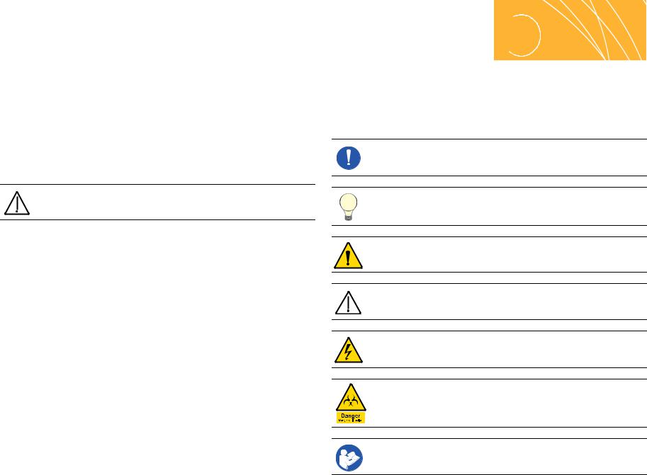
A-dec 200 System
A-dec 200 system comes configured as shown below:
Figure 1. A-dec 200 Systems
Cuspidor (page 55)
Assistant’s Instrumentation  (page 63)
Dental Chair  (page 7)
Serial Number Location
Footswitch 
Foot Control
Support Center |
|
(page 55) |
Dental Light |
|
(page 81) |
 Delivery System (page 35)
 Touchpad (page 31)
 Solids Collector
(page 66)
 Utilities
(page 73)
2 |
86.0016.00 Rev A |
Serial and Model Numbers
Product serial and model number information can be found on the serial/ model number labels. When you contact customer service, the serial number helps identify the product and when it was manufactured.
Use Table 1 and Figure 2 to reference how to identify serial/model number information.
Introduction
Table 1. Month Identification Table
Letter |
Month |
Letter |
Month |
|
|
|
|
A |
January |
G |
July |
|
|
|
|
B |
February |
H |
August |
|
|
|
|
C |
March |
I |
September |
|
|
|
|
D |
April |
J |
October |
|
|
|
|
E |
May |
K |
November |
|
|
|
|
F |
June |
L |
December |
|
|
|
|
Figure 2. Serial Number Label Example
200 |
1 |
|
2 |
(1) The REF number is the model number. (2) The first letter of the serial number indicates the month the product was manufactured. The first digit of the serial number is the year of manufacture (for example, L8 = December 2008).
86.0016.00 Rev A |
3 |

A-dec 200 Service Guide
Service Tools
This table lists the types of tools available from A-dec for servicing A-dec 200 equipment and their recommended use:
Table 2. Recommended Tools
Tool |
Task |
Part Illustration |
Part Number |
Drive air pressure gauge |
Adjusting handpiece drive air pressure, 0-60 psi (4.13 bar) |
|
50.0271.00 |
|
This gauge does not fit the Borden 3-hole coupler |
|
|
Hemostat |
• |
Troubleshooting or repairing a unit |
009.008.00 |
|
• |
Stopping air or water flow through tubing |
|
Hex key set |
Servicing or installing A-dec equipment (plastic case included) |
009.018.00 |
|
Loctite® |
Installing threaded fasteners to prevent loosening |
060.001.00 (Red 271) |
|
|
060.002.00 (Blue 242) |
O-ring tools |
Replacing O-rings during quick field repairs (fits the four |
009.013.00 |
|
smallest O-ring sizes) |
|
Panel mount gauge |
• Checking air/water pressure |
026.118.00 |
|
• Checking inline pressure gauge for testing purposes |
|
4 |
86.0016.00 Rev A |

Introduction
Table 2. Recommended Tools (continued)
Tool |
Task |
Part Illustration |
Part Number |
A-dec Silicone lubricant |
Lubricating internal moving parts such as O-rings, oral |
|
98.0090.01 |
|
evacuator valves, and bushings |
|
|
|
CAUTION Use only A-dec Silicone lubricant or |
|
|
|
the O-rings may be damaged. |
|
|
Sleeve tool |
Aiding in securing 1/4" tubing sleeves and 1/8" uni-clamps |
|
98.0072.00 |
Snap ring tool |
Installing and removing internal and external snap rings (fits |
|
009.007.00 |
|
all snap rings used in A-dec equipment) |
|
|
Tubing stripper |
Separating the extruded air and water lines in vinyl tubing |
|
009.035.00 |
Umbilical stringer |
Routing additional tubing or wiring through existing umbilical |
|
009.015.00 |
|
assemblies (12’ [3.66 meter] stringer with threading holes on |
|
|
|
both ends) |
|
|
Valve test syringe |
Testing of pilot operated valves; used to apply a static |
|
98.0050.01 |
|
pressure of 5-75 psi (.34-5.17 bar) |
|
|
86.0016.00 Rev A |
5 |
A-dec 200 Service Guide
6 |
86.0016.00 Rev A |
 2
2
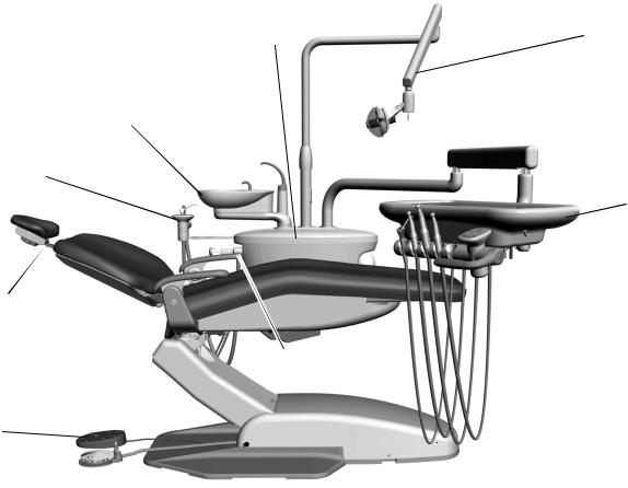
DENTAL CHAIR
This section provides detailed information related to service, maintenance, |
Figure 3. A-dec 200 Chair |
and adjustment of the A-dec 200 dental chair. |
|
Contents
•Product Overview, page 8
•Service, Maintenance, and Adjustments, page 10
•Illustrated Parts Breakdown, page 17
86.0016.00 Rev A |
7 |
A-dec 200 Service Guide
Product Overview
Chair Load Capacity
Maximum Chair Capacity:
•Patient Load 136 kg (300 lbs.)
•Module/Accessory Loads (maximum off-center) with A-dec 200 system: 68 kg (150 lbs.) @ 406 mm (16")
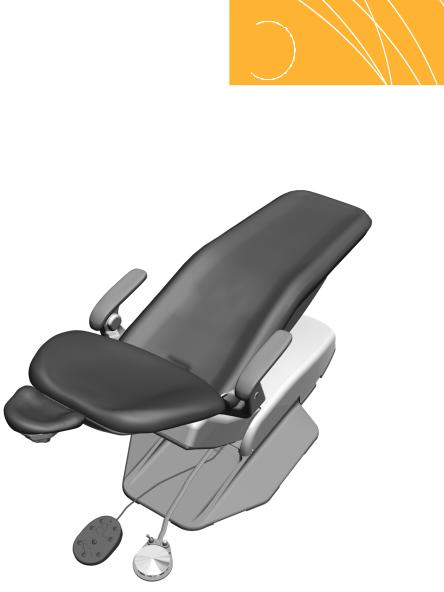
Power and Status
The chair and system is controlled by the master toggle on the delivery system. The power should always be turned off for service. When the A- dec logo on the touchpad or the status light on the chair lift arm are illuminated, the system is on and ready for use. If the status light blinks, the limit switch has been activated.
Figure 4. Power and Status
Master Toggle
(Power On/Off)
Status Light
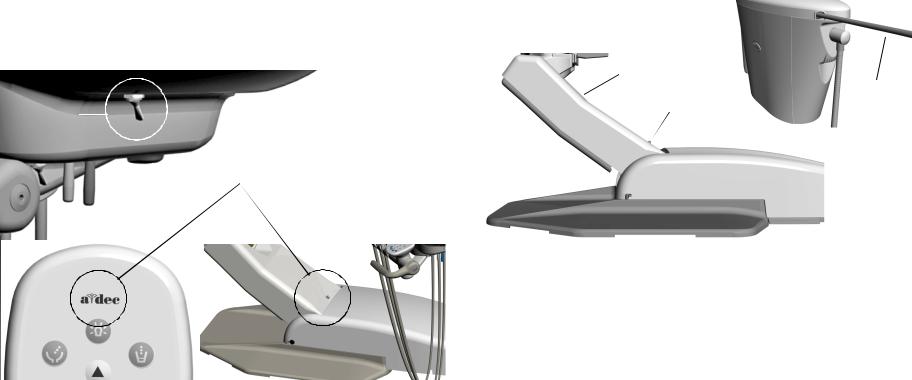
Limit Switch and Chair Lockout
If anything becomes lodged under the chair lift arm or assistant’s arm, a limit switch stops the downward motion of the chair. Pressing the chair stop plate or lifting up on the assistant’s arm activates the limit switches. Use the footswitch or touchpad to raise the chair, then remove the object.
The optional lockout kit inhibits the operation of the dental chair when a handpiece is removed from its holder and the foot control pressed. When this happens, the chair status light blinks quickly. To resume, replace the handpiece and use the footswitch or touchpad to raise the chair.
Figure 5. Chair Lockout Overview
Chair Lift Arm
Assistant’s
Arm
Status
Light
Chair Stop
Plate
|
|
|
|
|
|
|
|
8 |
|
|
86.0016.00 Rev A |
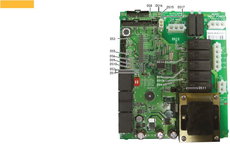
Circuit Board Components
Table 3. LED Identification
LED |
Status |
Description |
|
|
|
|
|
DS16 - AC power |
Off |
No 24 VAC power, tripped circuit |
|
LED |
|
breaker, power supply turned off, no |
|
|
|
line voltage |
|
|
|
|
|
|
Green, steady |
24VAC at the terminal strip |
|
|
|
|
|
DS15 - Status LED |
Off |
System is not functioning, no power or |
|
|
|
circuit board has failed |
|
|
|
|
|
|
Green, steady |
Normal operation |
|
|
|
|
|
DS17 - Data LED |
Off |
No DCS communication, not connected |
|
|
|
to the DCS, or DCS has failed |
|
|
|
|
|
|
Green, steady |
Detects active DCS |
|
|
|
|
|
|
Green, blinking |
Valid DCS Message |
|
|
|
|
|
DS6 Stop plate |
Off |
Closed, (normal) |
|
limit switch |
|
|
|
Red |
Open, (activated) |
||
|
|
|
|
DS4 - Chair |
Off |
Open, (normal) |
|
lockout |
|
|
|
Red |
Closed, (activated) |
||
|
|||
|
|
|
|
DS3 and DS5 - |
Off |
Potentiometer: |
|
Chair |
|
Not connected or bad connection |
|
potentiometers |
|
Moving in wrong direction |
|
|
|
Limited range of motion, or |
|
|
|
Cable is not on wheel |
|
|
|
|
|
|
Yellow, steady |
Normal operation |
|
|
|
|
|
|
Yellow, fast blink |
Upper end of travel |
|
|
|
|
|
DS7, DS13, |
Off |
Relay is off |
|
DS12, DS14 - |
|
|
|
On |
Relay is on |
||
Chair relay LEDs |
|
|
|
|
|
|
|
DS8 |
|
Capacitor switch |
|
|
|
|
|
DS9 |
|
Back up limit switch |
|
|
|
|
|
DS10 |
|
Base up limit switch |
|
|
|
|
|
DS11 |
|
off = relay is off; on = relay is on |
|
|
|
|
|
DS1, DS2 |
|
Position 3 function selection |
|
|
|
|
Dental Chair
Figure 6. Chair Circuit Board Components
86.0016.00 Rev A |
9 |

A-dec 200 Service Guide
Service, Maintenance, and Adjustments
Contents
•Potentiometers, page 11
•Hydraulic System, page 13
•Solenoids, page 14
•Test the Motor Pump, page 15
•Headrest Adjustments, page 16
•Chair Speed Adjustments, page 16
Factory Default Routine
When a new circuit board is installed in the chair, factory default routine needs to be run to learn the range of motion of the chair. The routine:
•Sets the base and back upper limits
•Calculates new presets based on actual range of motion of the chair
•Verifies that the potentiometers work
To start the factory default routine, place the “spare” jumper in the factory default position on the P17 test points of the chair circuit board (see "Circuit Board Components" on page 9 for reference).
When running the factory default routine the chair:
1.Moves base down
2.Moves base up
3.Moves back down
4.Moves back up
5.Moves base and back to Position 0
6.Beeps three times
NOTE The jumper must remain in the factory default position to complete the factory default routine. The status LEDs on the standard and deluxe touchpads and the chair circuit board double blink while the factory default routine is running and after the routine is complete.
10 |
86.0016.00 Rev A |

Potentiometers
Potentiometers provide the controller with current position values for the chair base and back. The controller saves the chair values when programmed and compares the values with current position values for the pre-position and auto-return functions.
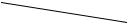
Adjust the Base Up Limit Switch:
1.Remove the motor pump cover.
2.Loosen the two screws clamping the limit switch to the mounting bracket.
Figure 7. Mounting Bracket
Switch Arm
Limit Switch


 Actuator Pin
Clamping
Screws
 Mounting
Bracket
Dental Chair
Figure 8. Chair Position
25" |
63.5 cm |
4.Push the limit switch against the actuator on the drive gear until the switch opens (clicks), then tighten the clamping screws. (See Figure 7).
5.Position the chair base down until the limit switch has closed, then position the chair full base up. Check the distance between the top of the base plate to the flat area around the threaded stud the chair adapter mounts to. If the distance is incorrect, repeat steps 2 through 4.
3. Position the chair as shown in Figure 8.
86.0016.00 Rev A |
11 |
A-dec 200 Service Guide
Adjust the Base Positioning Potentiometer
1.Remove the motor pump cover and position the chair base down.
2.Use a 3/16" hex key to remove the limit switch and mounting screw. See Figure 9.
3.Turn the potentiometer gear counterclockwise until it stops.
4.Align the potentiometer assembly, then turn the potentiometer gear clockwise two teeth.
5.Reinstall the limit switch and potentiometer assembly. Make sure the potentiometer gear does not turn and the two gears mesh properly.
6.Ensure that the electrical connections to the limit switch and positioning potentiometer are property set.
7.While observing the two gears for binding, lower the chair base.
CAUTION Do not raise to the full base up position until after you have checked the base up limit switch for proper adjustment. the chair may go into hydraulic lock if not adjusted properly.
8. Reinstall the cover, and program the auto-positioning functions.
Figure 9. Base Potentiometer
Potentiometer |
Large Drive |
|
Gear |
||
Gear |
||
|
Positioning
Potentiometer
Limit Switch |
Mounting
Screw
Adjust the Back Potentiometer
1.Position the chair back to its full up position.
2.Disconnect the limit switch wiring harness from the limit switch.
3.Remove the limit switch mounting screws and limit switch from the bracket. Do not bend the switch arm.
4.Remove the bracket mounting screws.
5.Remove the drive shaft from the potentiometer shaft.
6.Remove the drive shaft from the chair by moving it toward the chair backrest, and slightly to the side to dislodge it from the holder.
Figure 10. Remove Drive Shaft |
|
|
Limit Switch |
Switch Arm |
|
Mounting Screws |
|
|
|
|
Urethane Tubing |
Tip |
|
3/8" OD |
|
|
|
Bracket Mounting |
|
|
Screws |
|
Potentiometer |
|
Drive Shaft |
Shaft |
|
|
|
7.Turn the potentiometer shaft clockwise until it no longer turns, then turn the shaft counterclockwise 1/8" of a turn
Figure 11. Adjust Back Potentiometer
Potentiometer

 Shaft Counterclockwise


 Clockwise
8. Reinstall the shaft.
12 |
86.0016.00 Rev A |
Hydraulic System
The hydraulic system consists of:
•Hydraulic fluid reservoir
The fluid level in the reservoir can be seen through the sides of the reservoir and is serviced via a top fill cap.
•Hydraulic cylinders
The hydraulic cylinders control the base lift and back functions. Springs and gravity retract the rod during base and back down functions.
•Motor-driven hydraulic pump
The hydraulic pump and the starter capacitor supply hydraulic fluid from the reservoir, under pressure, to the chair lift and tilt hydraulic cylinders for back up and base up functions.
•Solenoid/manifold assembly
This assembly gates hydraulic fluid to and from the two cylinders. Depending on the chair function called for, the controller selects which solenoid-actuated manifold valves are opened or closed. The solenoid/ manifold assembly also includes four adjustable needle valves used to restrict or divert the flow of hydraulic fluid to and from the lift and tilt cylinders. These valves provide the rate of travel adjustment for chair base and back movement.
Dental Chair
Figure 12. Hydraulic System

 Hydraulic Cylinders
 Hydraulic Fluid Reservoir
Solenoid/Manifold


Assembly
Motor Pump
NOTE If cable ties are present in the product and you need to remove them for servicing, make sure to replace the ties after service is completed.
86.0016.00 Rev A |
13 |

A-dec 200 Service Guide
Solenoids
Test the Solenoid
To test the magnetic pull of the solenoid hold the tip of screwdriver near a solenoid and activate the appropriate chair function. You should feel the tug of the magnetic field generated around the solenoid.
Figure 13. Test the Solenoid
Remove and Replace the Solenoid
1.Lower the chair base and back to the full down position. Remove the motor pump cover, then unplug the chair.
WARNING The solenoid coils are powered by line voltage (100, 120, or 240 V). Failure to unplug the chair may result in serious injury from electrical shock.
2.Using a pair of wire cutters, cut the wiring to the faulty solenoid at about mid point between the solenoid and connector P10.
3.Using a 9/16" wrench, remove the solenoid retaining nut and slide the coil off the poppet sleeve.
CAUTION Use caution when removing and replacing the coil. The poppet sleeve is easily bent. Even slight bending of the sleeve will result in the malfunction of the solenoid valve.
4.Using a flat-tipped screwdriver, loosen and then remove the sleeve and poppet from the manifold assembly.
WARNING To prevent the possibility of over-heating and failure, replace the entire solenoid assembly.
5.Remove the o-ring from inside the manifold, and install a new o-ring.
6.Install a new sleeve and poppet; tighten the poppet sleeve using a flattipped screwdriver.
7.Install a new coil on the plunger. Do not overtighten the retaining nut.
8.Strip approximately 1/4" of insulation from the wires cut in step 2, and install a crimp-on butt-type connector on each wire.
9.On the new solenoid, cut the wiring to length allowing enough to reach the crimped-on connectors. Strip approximately 1/4" of insulation from the wires and crimp each wire into a connector.
Figure 14. Remove and Replace Solenoid
Hydraulic
Manifold
O-ring
Poppet
Poppet Washer
Sleeve
Solenoid
P10
ID Washer (Solenoid
Specifications)
14 |
86.0016.00 Rev A |
Dental Chair
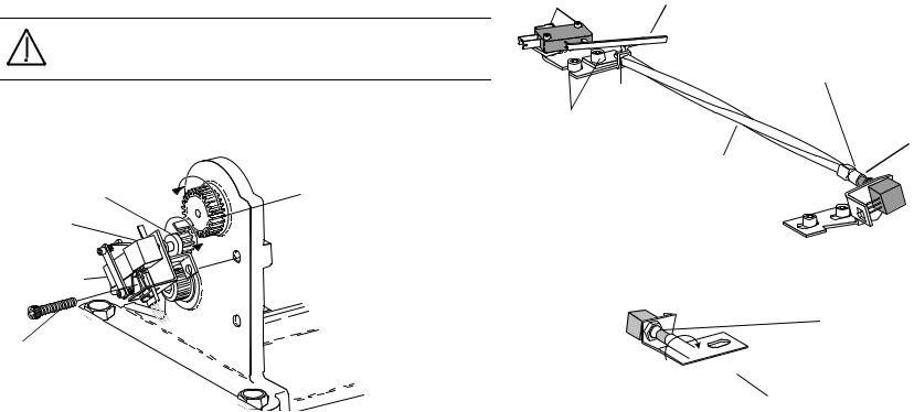
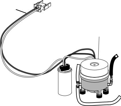
Test the Motor Pump
This test requires the use of a current pickup probe.
•Clip the probe onto the red wire going to the motor pump.
•Use the footswitch or touchpad to raise the chair.
You should read 5 Amps (maximum) of current for 120 V motor pump, or 2.5 Amps (maximum) of current for 240 V motor pump.
Figure 15. Test Motor Pump
Red Wire
 White Wire
Motor Pump
|
|
|
86.0016.00 Rev A |
15 |
|

A-dec 200 Service Guide
Headrest Adjustments
Turn the locking knob clockwise to lock it into the desired position. Slide the headrest and glide bar up or down to adjust the height.
WARNING When the glidebar has reached its maximum recommended working height, a warning will be visible on the patient’s side of the glide bar. Do not use the headrest in a position where this warning is visible.
Figure 16. Headrest Adjustments
Locking
Knob
Glide Bar 
Chair Speed Adjustments
The speed for moving the chair seat and back can be adjusted. Use a 3/32" hex key to adjust the chair base speed and back speed on the manifold (see
Figure 17. Adjust Manifold for Chair Speed
|
|
|
|
|
|
|
|
|
|
|
|
|
|
Adjust chair |
Adjust chair |
|
|
|
|
|
|
|
|
|
|
|
|
|
back speed. |
|
|
|
|
|
|
|
|
|
|
|
|
|
|
|
base speed. |
|
|
|
|
|
|
|
|
|
|
|
|
|
|
|
|
|
|
|
|
|
|
|
|
|
|
|
|
|
|
|
|
|
|
|
|
|
|
|
|
|
|
|
|
|
|
|
|
|
|
|
|
|
|
|
|
|
|
|
|
|
|
|
|
|
|
|
|
|
|
|
|
|
|
|
|
|
|
|
|
|
|
|
|
|
|
|
|
|
|
|
|
|
|
|
|
|
|
|
|
|
|
|
|
|
|
|
|
|
|
|
|
|
|
|
|
|
|
|
|
|
|
|
|
|
|
|
|
|
|
|
|
|
|
|
|
|
|
|
|
|
|
|
|
|
|
|
|
|
|
|
|
|
|
|
|
|
|
|
|
|
|
|
|
|
|
|
|
|
|
|
|
|
|
|
|
|
|
|
|
|
|
|
|
|
|
|
|
|
|
|
|
|
|
|
|
|
|
|
|
|
|
|
|
|
|
|
|
|
|
|
|
|
|
|
|
|
|
|
|
|
|
|
|
NOTE If cable ties are present in the product and you need to remove them for servicing, make sure to replace the ties after service is completed.
16 |
86.0016.00 Rev A |
Illustrated Parts Breakdown
Part Identification
In this section, you will find serviceable components tables that correspond to the illustrations. The tables identify all parts and kits, including those that are not for sale. Parts that are not for sale are indicated with the symbol shown below:
†— Indicates that the individual part is not available for sale. These parts are typically part of a kit and/or larger assembly that is for sale.
Contents
•Chair Covers, page 17
•Upper Chair Assembly, page 18
•Mid Chair Assembly, page 20
•Lower Chair Assembly, page 22
•Headrest Assembly, page 23
•Motor Pump and Capacitor Assembly, page 24
•Hydraulic Manifold Assembly, page 26
•Hydraulic Tank Assembly, page 27
•Base Limit Switch Assembly, page 27
•Back Potentiometer Assembly, page 28
•Base Position Potentiometer Assembly, page 29
Dental Chair
Chair Covers
Figure 18. A-dec 200 Dental Chair
1
 2 5
2 5 


3
4
Item |
Part Number |
Description |
|
|
|
1 |
61.3821.00 |
Rear chair cover |
|
|
|
2 |
61.3847.00 |
Bottom cover |
|
|
|
3 |
61.3846.00 |
Utility cover |
|
|
|
4 |
61.2239.01 |
Lift arm cover |
|
|
|
5 |
61.2242.00 |
Umbilical routing bracket |
|
|
|
86.0016.00 Rev A |
17 |

A-dec 200 Service Guide
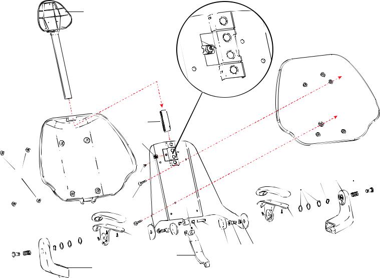
Upper Chair Assembly
Item |
Part Number |
Description |
|
|
|
1 |
— |
Double articulating headrest assembly (see page 23) |
|
|
|
2 |
61.3824.00 |
Backrest cover |
|
|
|
3 |
61.3791.00 |
Armrest release button |
|
|
|
4 |
013.052.00 |
Compression spring, .843 OD X 1.375 FL |
|
|
|
5 |
61.1245.02 † |
Arm support, LH |
|
|
|
6 |
004.157.00 |
Wave spring washer, .990 OD stainless steel |
|
|
|
7 |
004.126.00 |
Flat washer |
|
|
|
8 |
61.3827.00 |
Armrest cover |
|
|
|
9 |
61.3790.01 |
Armrest pivot plate, LH |
|
|
|
10 |
005.123.01 |
Button head socket screw, 10-32 X 5/8" |
|
|
|
11 |
61.3108.00 |
Flanged bearing |
|
|
|
12 |
001.164.00 |
Socket shoulder screw, 1/2-13 X 5/8 X 5/8 |
|
|
|
13 |
61.3788.01 |
Pivot bolt cover |
|
|
|
14 |
61.2740.00 |
Backrest link pin |
|
|
|
15 |
016.131.00 |
Flanged bearing |
|
|
|
16 |
007.069.00 |
Set screw, socket 1/4-20 X 1/4 |
|
|
|
17 |
61.3792.00 |
Back link |
|
|
|
18 |
61.3789.01 |
Armrest pivot plate, RH |
|
|
|
19 |
005.147.00 |
Flat head socket screw, 1/4-20 X 1-1/4 |
|
|
|
20 |
006.122.01 |
Retainer nut, 10-32 zinc |
|
|
|
21 |
61.2743.00 |
Brake shoe |
|
|
|
22 |
61.1247.02 † |
Arm support, RH |
|
|
|
23 |
001.268.00 |
Socket screw, 1/4-20 X 3/30 mm stainless steel |
|
|
|
24 |
002.136.00 |
Flat head socket screw, 1/4-20 X 1/38 |
|
|
|
† Indicates that the individual part is not available for sale
18 |
86.0016.00 Rev A |
Dental Chair
Figure 19. Upper Chair Assembly
1
Headrest Assembly (see page 23)
2 |
|
|
|
|
21 |
|
|
|
|
|
20 |
23 |
|
19 |
|
|
|
8 |
24 |
|
|
|
18 |
|
|
|
17
22
21
20 
8 |
7 |
6 |
5 |
4 |
3 |
||
|
|
|
|
|
|
||
|
|
|
|
|
|
|
|
|
|
|
|
|
|
|
|
16 |
|
|
|
14 |
|
|
|
|
|
9 |
|
|
10 |
||
15 |
|
||
|
|
|
|
13 |
12 |
11 |
|
86.0016.00 Rev A |
19 |

A-dec 200 Service Guide
Mid Chair Assembly
Item |
Part Number |
Description |
Item |
Part Number |
Description |
|
|
|
|
|
|
1 |
61.1309.00 |
Tilt slide block |
21 |
35.1749.00 |
Chair mount adaptor |
|
|
|
|
|
|
2 |
61.1311.00 |
Tilt cylinder clevis rod |
22 |
004.171.00 |
Thrust washer |
|
|
|
|
|
|
3 |
61.1267.00 |
Tilt cylinder assembly |
23 |
006.124.00 |
5/8-18 UNF-2B ESNA 4N zinc |
|
|
|
|
|
|
4 |
010.031.00 |
E-clip |
24 |
025.072.00 |
Cable tie mounting block |
|
|
|
|
|
|
5 |
61.2076.00 |
Roller arm link |
25 |
005.143.00 |
Button head socket screw, 1/4-20 X 3/8" |
|
|
|
|
|
|
6 |
61.2078.00 |
Toeboard axle |
26 |
61.1294.00 † Lower structure link |
|
|
|
|
|
|
|
7 |
61.2293.00 |
Linkarm roller |
27 |
41.1145.00 |
Umbilical support |
|
|
|
|
|
|
8 |
005.008.01 |
Socket head screw, 1/4-20 X 1/2" |
28 |
41.1143.00 |
Umbilical restraint |
|
|
|
|
|
|
9 |
025.044.00 |
Clamp |
29 |
61.2095.00 † |
Lift arm |
|
|
|
|
|
|
10 |
61.1308.00 |
Channel guide |
30 |
004.149.00 |
Flat neoprene washer, .680 ID |
|
|
|
|
|
|
11 |
013.054.00 |
Spring |
31 |
004.104.00 |
Flat steel plated washer, .640 ID |
|
|
|
|
|
|
12 |
002.134.00 |
Socket head screw, 1/4-20 X 1/4" |
32 |
— |
Lift cylinder |
|
|
|
|
|
|
13 |
61.1221.00 |
Base limit switch assembly |
33 |
61.1285.00 |
Lift pin |
|
|
|
|
|
|
14 |
61.1224.00 |
Back position potentiometer assembly |
34 |
011.046.00 |
Clip pin |
|
|
|
|
|
|
15 |
002.023.00 |
Head screw, 3/8-16 X 1-1/4 |
35 |
41.1144.00 |
Umbilical retainer |
|
|
|
|
|
|
16 |
61.1314.00 |
Wear pad |
36 |
001.165.00 |
Socket head shoulder screw |
|
|
|
|
|
|
17 |
002.120.00 |
Socket head patch screw, 1/4-20 X 1" stainless steel |
37 |
001.164.00 |
Socket head shoulder bolt |
|
|
|
|
|
|
18 |
004.148.00 |
Flat nylatron washer, .630 ID |
38 |
61.3825.00 † |
Swivel bracket |
|
|
|
|
|
|
19 |
— |
Seat armature |
39 |
61.3826.00 † Upper structure, gray 3 |
|
|
|
|
|
|
|
20 |
61.1270.00 |
Stud |
|
|
|
|
|
|
|
|
|
† Indicates that the individual part is not available for sale
20 |
86.0016.00 Rev A |

Dental Chair
Figure 20. Mid Chair Assembly
1 |
|
2 |
3 |
4 |
|
|
|
|
4 |
|||
|
|
|
|
|
||||||||
|
|
|
|
|
|
|
|
|
|
|
|
|
|
|
|
|
|
|
|
|
|
5 |
|
|
|
4 |
|
|
|
|
|
|
4 |
|
|
|
|
|
|
|
|
|
|
|
|
|
|
|
|
|
|
5 |
|
|
|
|
|
6 |
|
|
|
|||
|
|
13 Base Limit Switch |
|
|
7 |
|
|
|
|
|||
|
|
|
|
|
7 |
|
|
|
||||
|
|
(see page 27) |
|
|
|
|
|
8 |
|
|
|
|
|
14 Back Potentiometer |
|
|
|
|
10 |
|
|
||||
|
|
|
|
|
|
|
||||||
|
|
|
12 |
11 |
19 |
|||||||
|
(See page 28) |
|
|
|
||||||||
|
|
|
|
|
|
|
|
|
|
|
|
|
|
|
|
15 |
16 |
|
|
|
|
|
|
|
|
|
|||
|
|
|
|
|
|
|
|
|
|
|
|
|
|
|
|
|
|
|
|
|
|
|
|
|
|||||
|
|
|
39 |
|
|
|
|
38 |
|
|
|
|
17 |
|
|
|
|
|
|||||||||||
|
|
|
|
|
|
|
|
|
|
|
|
|
|
|
|||||||||||||||
|
|
|
|
|
|
|
|
|
|
|
|
|
|
|
|||||||||||||||
|
|
|
|
|
|
|
|
|
|
|
|
|
|
|
|||||||||||||||
|
|
|
|
18 |
|
|
|
|
|
|
|
|
|
|
|||||||||||||||
|
|
|
|
|
|
|
|
|
|||||||||||||||||||||
|
|
|
|
|
|
|
|
|
|
|
|
|
|
|
|
||||||||||||||
|
|
|
|
|
|
|
|
18 |
|
|
|
|
|
|
|
|
20 |
||||||||||||
|
37 |
|
|
|
|
|
|
18 |
22 |
|
|
|
|
|
|||||||||||||||
|
|
|
|
|
|
|
|
|
|
||||||||||||||||||||
|
|
|
|
|
|
|
|
|
|
|
|
23 |
|||||||||||||||||
|
26 |
|
|
|
|
|
|
|
|
|
|
|
|||||||||||||||||
|
|
|
|
|
|
|
|
|
|
|
|
||||||||||||||||||
|
|
|
|
|
|
|
|
|
|
|
|
||||||||||||||||||
|
|
28 |
|
27 |
|
|
26 |
||||||||||||||||||||||
|
|
|
|
|
|
|
|
|
|||||||||||||||||||||
|
36 |
|
|
|
|
|
|
|
|
|
|
|
|
|
|
|
|||||||||||||
|
|
|
|
|
|
|
|
|
|
|
|
|
|
|
|||||||||||||||
|
|
|
|
|
|
|
|
|
|
|
|
|
|
|
|
|
|
|
|
|
|||||||||
|
|
|
|
|
|
|
|
|
|
|
|
18 |
|
|
|
|
|
|
|
|
|
||||||||
|
|
|
|
|
|
|
|
|
|
|
|
|
|
|
|
|
|
|
|
|
|||||||||
|
|
|
|
|
|
|
|
|
|
|
|
|
|
|
|
|
|
|
|
|
|
|
|
|
|
|
|
|
|
18


 29
29
35 |
|
30 |
||||||||
34 |
|
|
|
|
|
|
31 |
|||
|
|
|
|
|
|
|||||
|
|
|
|
|
|
|
|
|
||
|
|
|
|
|
|
|
|
|
||
|
32 |
|||||||||
|
4 |
|
|
|
|
4 |
||||
|
33 |
|
|
|
|
|
|
|
||
|
|
|
|
|
|
|
|
|
||
|
|
|
|
|
|
|
|
|||
21
24 |
25 |
|
Lower Chair
(see page 22)
86.0016.00 Rev A |
21 |

A-dec 200 Service Guide
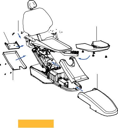
Lower Chair Assembly
|
|
|
Figure 21. |
|
Item |
Part Number |
Description |
||
|
||||
|
|
|
|
|
1 |
010.031.01 |
E-clip |
||
|
|
|
|
|
2 |
61.1285.00 |
Pivot pin |
||
|
|
|
|
|
3 |
001.163.00 |
Hex head cap screw, 1/2-13 X 1-1/4 |
||
|
|
|
|
|
4 |
004.148.00 |
Flat nylatron washer, .630 ID |
||
|
|
|
|
|
5 |
001.165.00 |
Socket head shoulder screw |
||
|
|
|
|
|
6 |
005.008.01 |
Socket head screw, 1/4-20 X 1/2 |
||
|
|
|
|
|
7 |
61.1277.01 † |
Sub base |
||
|
|
|
|
|
8 |
61.3848.00 |
Floorbox/pump cover |
||
|
|
|
|
|
9 |
61.1650.00 |
Foot switch/foot control bracket |
||
|
|
|
|
|
10 |
61.2037.01 |
Baseplate |
||
|
|
|
|
|
11 |
61.1286.00 |
Bracket |
||
|
|
|
|
|
12 |
005.143.00 |
Button head socket screw, 1/4-20 X 3/8 |
||
|
|
|
|
|
13 |
61.1221.00 |
Base position potentiometer assembly |
||
|
|
|
|
|
14 |
61.1295.00 |
Gear |
||
|
|
|
|
|
† Indicates that the individual part is not available for sale
1
2
Lower Chair Assembly
Upper Chair Assembly (see page 18)
1 |
Mid Chair Assembly |
2 |
(see page 20) |
|
3 |
4 |
|
|
5 |
|
14 |
6 |
13 |
|
7 |
12 |
|
8 |
9 |
|
|
11 |
|
|
|
|
10


Motor Pump Assembly (see page 24) 
22 |
86.0016.00 Rev A |
Loading...