


Chairs |
Overview |
|
|
A-dec model 1040, 1021 and 8000 chairs are electronically controlled, hydraulically powered dental chairs. Buttons on both the touchpad and 8-button footswitch and actuators on the 8-function footswitch are used to position and program auto-positioning functions into the chair. The hydraulic system is controlled by the electronic control module using relays and solenoidactuated valves.
This section provides information related to locating serial/model numbers, servicing, maintenance, and adjustment of chairs. Detail on how to service chairs and troubleshoot specific problems related to them is presented.
85.0812.00, 2003 |
CH-1 |

Chairs |
Serial/Model Number Locations |
|
|
Locating
Serial/Model
Number
The serial/model number tags identify the chair model and manufacture date. The label can be found either on the top surface of a chair’s upper structure (raise the toeboard) or on the righthand side of the upper structure. If you have difficulty locating the serial/model number label, the following example may be helpful.
Serial number label location
Serial number label location
Decade 1021/1011 Chair |
Cascade 1040 Chair |
85.0812.00, 2003 |
CH-2 |

Chairs |
Manufacture Date |
|
|
Reading the
Manufacture Date
Different models of the chair can be identified by referring to the “REF” number. Each chair is further identified by its month and year of manufacture.
This example shows how to identify the model and month and year of manufacture of the chair.
Item # Description
1Model number
2The first letter of the serial number indicates the month the product was manufactured; e.g., A is January.
3First digit indicates the year of manufacture.
1
1
|
Tele: (44) 1203-350901 |
||||
DENTAL |
REF: 1040 |
|
S/N: J167856 |
||
CHAIR |
|
||||
MADE IN |
|
! |
|
INPUTS |
|
USA |
|
|
|
||
|
|
120 V - |
|||
|
|
10 AMPS MAX |
|||
2001 |
|
50-60 Hz |
|||
|
|
|
|
||
DENTAL CHAIR
CAUTION!
C  US
US
®
LISTED 15VJ
LA BEL P/N: 051.515.02 REV L
Serial/Model Number Label
85.0812.00, 2003 |
CH-3 |
Chairs |
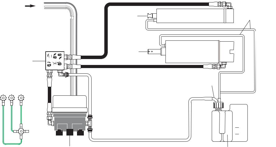
Hydraulics |
|
|
Working with Hydraulics
The hydraulic system consists of the following:
Part |
Description |
Hydraulic fluid reservoir |
The fluid level in the reservoir can be seen through the sides of the reservoir and is serviced via a |
|
top fill cap. |
|
|
Hydraulic cylinders |
The hydraulic cylinders control the base lift and back functions. Springs and gravity retract the |
|
rod during base and back down functions. |
|
|
Motor-driven hydraulic pump |
The hydraulic pump and the starter capacitor supply hydraulic fluid from the reservoir, under |
|
pressure, to the chair lift and tilt hydraulic cylinders for back up and base up functions. |
|
|
Solenoid/manifold assembly |
This assembly gates hydraulic fluid to and from the two cylinders. Depending on the chair |
|
function called for, the controller selects which solenoid-actuated manifold valves are opened or |
|
closed. The solenoid/manifold assembly also includes four adjustable needle valves used to |
|
restrict or divert the flow of hydraulic fluid to and from the lift and tilt cylinders. These valves |
|
provide the rate of travel adjustment for chair base and back movement. |
|
|
85.0812.00, 2003 |
CH-4 |
Chairs |
Hydraulic System Flow Diagram |
|
|
From
motor/pump { start capacitor
Tilt cylinder
Lift cylinder
Solenoid manifold assembly
Hydraulic pump motor
Vent tubes
Pickup tube
MAX
MIN
Hydraulic fluid reservoir (check fluid level with base and back full up)
NOTE: Use only A-dec fluid P/N 61.0197.00.
85.0812.00, 2003 |
CH-5 |
Chairs |
|
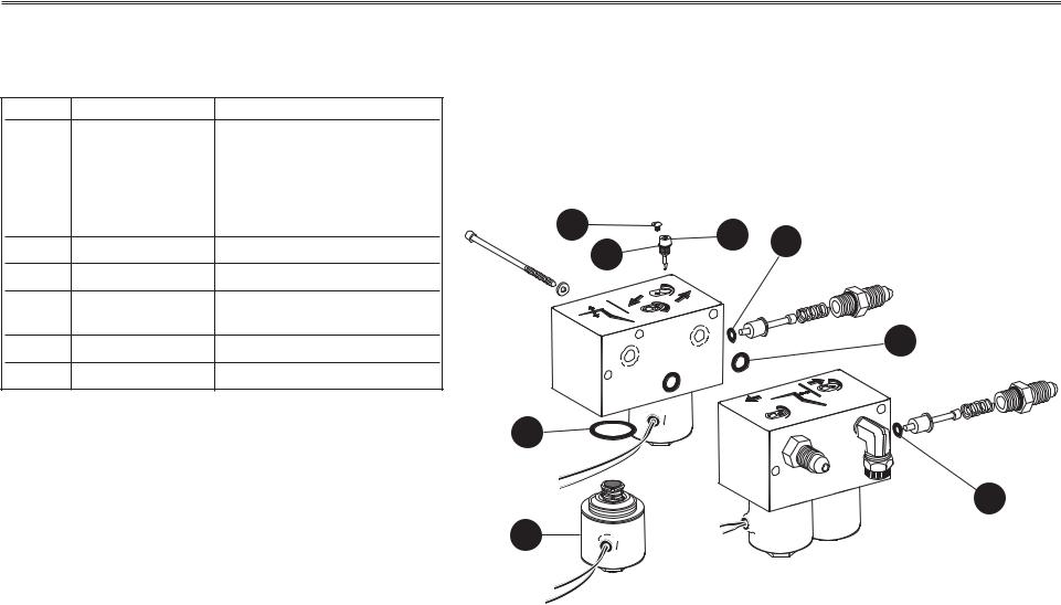
Hydraulic Manifold |
||
|
|
|
Before January 1999 |
|
Hydraulic Manifold |
|
|
||
Item # |
Part Number |
Description |
|
|
1 |
61.1335.00 |
Solenoid, (8-watt, 100V, |
|
|
|
|
Yellow wires) |
|
|
|
61.1336.00 |
Solenoid, (8-watt, 120 V, |
|
|
|
|
Black wires) |
|
|
|
61.1337.00 |
Solenoid, (8-watt, 240 V, |
6 |
|
|
|
Red wires) |
||
2 |
035.041.02 |
O-ring, special pkg 10 |
3 |
|
3 |
030.004.02 |
O-ring, AS568-004 pkg 10 |
|
|
4 |
030.010.00 |
O-ring, AS568-010 |
|
|
|
|
(only on dual-block manifolds) |
4 |
|
5 |
61.0460.00 |
Flow adjust screw with o-ring |
||
|
||||
6 |
001.002.00 |
Screw, truss-head slot |
|
|
|
|
|
2 |
|
|
|
|
3 |
|
85.0812.00, 2003 |
CH-6 |

Chairs |
Hydraulic Manifold |
|
|
Hydraulic Manifold
|
Item # |
Part Number |
Description |
|
|
|
|
1 |
61.1335.01 |
Solenoid, (8-watt, 100V, |
|
|
|
|
|
|
Yellow wires) |
|
|
|
|
|
61.1336.01 |
Solenoid, (8-watt, 120V, |
|
|
|
|
|
|
Black wires) |
|
|
|
|
|
61.1337.01 |
Solenoid, (8-watt, 240V, |
|
|
|
|
|
|
Red wires) |
|
|
|
|
|
|
|
|
|
|
|
2 |
030.015.02 |
O-ring, pkg 10 |
|
|
|
|
|
|
|
|
|
|
|
3 |
030.004.02 |
O-ring, AS568-004 pkg 10 |
|
|
|
|
|
|
|
|
|
|
|
4 |
61.0460.00 |
Flow adjust screw with o-ring |
|
|
|
|
|
|
|
|
|
|
|
5 |
002.118.01 |
Screw, button-head, socket |
|
|
|
|
|
|
|
|
|
|
|
6 |
61.1332.00 |
Manifold assy, hyd, 100V |
|
|
|
|
|
61.1333.00 |
Manifold assy, hyd, 120V |
|
|
|
|
|
|
|
6 |
||
|
|
61.1334.00 |
Manifold assy, hyd, 240V |
|
|
|
|
|
|
|
|
||
|
|
|
|
|
|
|
|
|
|
|
|
|
|
After January 1999
5
4
3 |
3 |
1
85.0812.00, 2003 |
CH-7 |
Chair |
Hydraulic Manifold |
|
|
Removing a
Solenoid
WARNING
The solenoid coils are powered by line voltage (100, 120, or 240V AC). Failure to unplug the chair may result in serious injury from electrical shock.
The following steps will guide you through the removal of a solenoid.
Task |
Description |
Hydraulic manifold |
|
|
|
1 |
Lower the chair base and back to the |
J10 |
|
full down position to depressurize the |
|
|
hydraulic system. Remove the motor |
|
|
pump cover, then unplug the chair. |
|
2If necessary, remove the two mounting screws that secure the manifold to the hydraulic tray. Rotate the manifold so the solenoids are accessible.
3Using a flat blade screwdriver and a 9/16" wrench, remove the defective solenoid.
4Cut the defective solenoid wires 3" (74mm) from the coil and discard.
5Remove the old o-ring from the solenoid cavity and completely dry the cavity. Replace the o-ring (refer to Solenoid installation instructions for correct o-ring).
 O-ring
Poppet
Wire nut
Poppet sleeve
Washer
 Coil
Coil
 ID washer
Retaining nut
Removing a Solenoid
85.0812.00, 2003 |
CH-8 |

Chair |
Hydraulic Manifold |
|
|
Replacing a
Solenoid
WARNING
The solenoid coils are powered by line voltage (100, 120, or 240V AC). Failure to unplug the chair may result in serious injury from electrical shock.
The following steps will guide you through replacing a solenoid.
Task |
Description |
|
1 |
Install the new solenoid stem and poppet into |
Hydraulic manifold |
|
the manifold and tighten to 35-40 in lb |
J10 |
|
(.11085-.2284 Nm). Position the remaining |
|
|
|
|
|
solenoid parts on the stem and secure by |
|
|
tightening the retaining nut to 25-30 in lb |
|
|
(.14275-.1713 Nm). |
|
2Cut the solenoid wires 3" (75 mm) from the coil. Install the stripped wires from the solenoid and the connector housing into a wire nut. Repeat for the remaining wire.
3Using the mounting screws, secure the manifold to the hydraulic tray.
4.Plug in the chair. Test the chair functions to ensure proper operations and that no fluid leakage occurs. Reinstall the motor pump cover.
 O-ring
Poppet
Wire nut
Poppet sleeve
Washer
 Coil
Coil
 ID washer
Retaining nut
Replacing a Solenoid
85.0812.00, 2003 |
CH-9 |

Chairs |
Hydraulic Manifold |
|
|
Adjusting the
Hydraulic Manifold
CAUTION
Do not completely close a speed control valve.
The motor/pump could overheat and become damaged from pumping against a closed valve.
Do not remove retaining screw from the control valves.
The hydraulic manifold incorporates four speed control valves, which restrict or divert the flow of hydraulic fluid to and from the lift and tilt cylinders.
NOTE: The speed control valves are hex drive.
|
To adjust... |
Do this... |
|
|
Base up speed |
Turn base up control valve: |
|
|
|
clockwise to decrease speed, or |
|
|
|
counterclockwise to increase speed. |
|
|
|
|
|
|
Base down speed |
Turn base down control valve: |
|
|
|
clockwise to decrease speed, or |
|
|
|
counterclockwise to increase speed |
|
|
|
|
|
|
Back up speed |
Turn back up control valve |
|
|
|
counterclockwise to decrease speed, or |
|
|
|
clockwise to increase speed. |
|
|
|
NOTE: This is opposite of the other |
|
|
|
three control valves. Turning the back |
|
|
|
up valve counterclockwise too far may |
|
|
|
prevent the back from moving up. |
|
|
|
|
|
|
Back down speed |
Turn the back down control valve: |
|
|
|
clockwise to decrease speed, or |
|
|
|
counterclockwise to increase speed. |
|
|
|
|
|
Base up |
Back up |
control valve |
control valve |
Retaining screw
Base down |
Back down |
control valve |
control valve |
Adjusting the Hydraulic Manifold
85.0812.00, 2003 |
CH-10 |
Chairs |
Hydraulic Manifold |
|
|
Correcting
Hydrostatic
Lock
Hydraulic lock occurs based on the following conditions:
•chair base or back is stuck in full up position
•limit switch not activated, or
•down solenoid poppet is unable to open based on excess hydraulic pressure.
Task Description
1Remove the motor/pump cover from the chair.
2Fit a 5/8" wrench to the high pressure outlet port (either lift or tilt, whichever is in hydrostatic lock) of the hydraulic manifold. Hold the port still and use a 9/16" wrench to loosen the hose fitting.
3Place a shop rag around the fitting to absorb the fluid.
4Carefully loosen the fitting counterclockwise until oil begins to leak from the fitting. Retighten the fitting. Operate the down function. A second release of hydraulic fluid may be required.
5Adjust the limit switch that caused the hydrostatic lock (refer to Adjusting the Base Up Limit Switch). In some cases, it may be necessary to remove and replace the limit switch. Adjust the new limit switch as needed. Also ensure that the large gear/actuator is securely installed and not slipping.
6Cycle the chair a couple of times to verify it is no longer in hydrostatic lock.
Tilt cylinder high pressure fitting
Lift cylinder high pressure fitting
Correcting Hydrostatic Lock
85.0812.00, 2003 |
CH-11 |
Chairs |
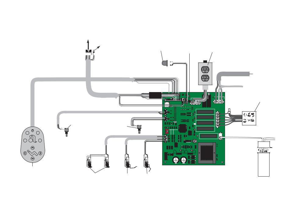
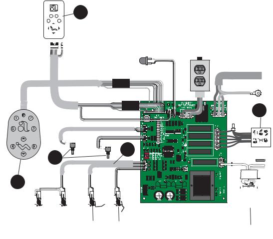
Electrical System Wiring Diagram |
|
|
NOTE: If there is no cuspidor, remove
To post box, or jumper from cable and place on board
Radius lift arm connector
To cuspidor |
|
|
|
|
|
Place jumper |
|
|
stop switch |
|
LED light |
|
|
here if there is |
|
|
|
|
|
|
no cuspidor |
|
|
|||
|
|
|
|
|
|
|||
|
|
|
|
|
|
|
|
|
|
|
|
|
|
|
|
|
|
|
|
|
|
|
|
|
|
|
|
|
|
|
|
|
|
|
|
|
|
|
|
|
|
|
|
|
|
|
|
|
|
|
|
|
|
|
|
|
|
|
|
|
|
|
|
|
|
|
|
|
|
|
|
1 2
0 3
Back positioning |
Base positioning |
potentiometer |
potentiometer |
P1 |
DS8 |
DS15 |
AUXILIARY |
|
|
P14 |
P16 |
OUTPUT POWER |
|
|
(2A MAX) |
|||
P2 |
CUSP |
STATUS |
||
|
|
L1 |
N/L2 |
|
|
|
|
||
S1 PRGM 
P5 |
|
OT |
DS3 |
P |
|
B K |
|
P4 |
|
OT |
DS5 |
P |
|
BS |
|
P12
P17
TEST POINTS
|
|
|
B KUP |
|
|
|
||
|
|
|
BSUP |
|
|
|
|
|
|
|
|
BSDN |
|
|
|
|
|
|
|
|
B KDN |
|
|
BK UP |
||
|
|
|
PRGM 0 |
|||||
|
|
|
PRGM 1 |
DS12 |
|
|||
|
|
|
PRGM 2 |
|
|
|
|
|
|
|
|
PRGM 3 |
|
|
|
|
|
|
|
|
EN/DIS TP/FS |
BS UP |
||||
|
|
|
FA CT DEFAULT |
|||||
|
|
|
B K POT |
DS14 |
|
|||
|
|
|
BS POT |
|
|
|
||
|
|
|
SPARE |
|
|
|
|
|
|
|
|
SPARE |
|
|
BS DN |
||
|
|
|
|
|
|
|||
|
|
|
|
|
DS7 |
|
DS1 |
DS2 |
|
|
|
|
|
|
|
|
|
"STATIC SENSITIVE" |
BK DN |
|
ON |
|
#1 |
#2 |
SETS |
DS13 |
|
S2 |
|
OFF OFF |
CUSP/RET |
|
|
|
|
ON |
OFF |
LAST POST |
|
K5 |
|
1 |
2 |
OFF ON |
PRGM 3 |
DS11 |
||
PS |
|
DS6 |
ON |
NOT USED |
PUMP |
|
P6 |
|
ON |
|
|||
B K |
|
DS9 |
|
|
P13 |
|
|
|
|
LOCKOUT |
|||
|
|
DS10 |
|
|
DS4 |
|
BS |
|
|
|
|
|
|
CB1
CB2
Optional duplex 100V and 120V only
Main power from electrical outlet

 Ground
MAINS
INPUT POWER
 L1
L1 

 N/L2
N/L2
P11 


P10
N/L2
BK UP
BS UP
BS DN
BK DN
P9
PUMP


 PUMP
PUMP

 N/L2
N/L2
Hydraulic manifold
To hydraulic motor/pump
 }
} 
~)
|
R73 |
(220-240V |
|
DS17 |
DS16 |
|
|
+12V |
+5V |
|
|
BE EPER |
R74 R72 |
(100-120V~) |
PART # |
 Capacitor
Footswitch
Stop plate |
Back up limit |
Base up limit |
|
|||||
limit switches |
switch |
switch |
|
|||||
|
|
|
|
|
|
|
|
|
|
|
|
|
|
|
|
|
|
85.0812.00, 2003 |
CH-12 |
Chairs |
Electrical Systems Service Parts |
|
|
|
Item # |
Part Number |
Description |
|
|
1 |
61.1332.00 |
100V, Yellow wires |
|
|
|
61.1333.00 |
120V, Black wires |
|
|
|
61.1334.00 |
240V, Red wires |
|
|
|
|
|
|
|
2 |
90.1031.00 |
Capacitor with boot (100-120V) |
|
|
|
90.1034.00 |
Capacitor with boot (240V) |
|
|
|
|
|
|
|
3 |
041.372.00 |
Positioning potentiometer |
|
|
|
|
|
|
|
4 |
61.2065.00 |
Back up limit switch |
|
|
|
|
|
|
|
5 |
044.184.01 |
Base up limit switch |
|
|
|
|
|
|
|
6 |
61.2099.00 |
Cable assy, tilt switch |
|
|
|
|
(1040) only |
|
|
|
|
|
|
|
7 |
61.3043.00 |
8-button footswitch |
|
|
|
|
|
|
|
8 |
39.1045.00 |
Chair touchpad |
|
|
|
39.1385.00 |
Performer touchpad |
|
|
|
39.1090.00 |
Cascade Master with cuspidor |
|
|
|
39.1090.00 |
Cascade Master w/o cuspidor |
|
|
|
|
|
|
7
8
1 2
0 3
1
6 |
3
|
|
|
|
|
|
|
|
|
|
|
|
|
|
|
|
|
|
|
|
|
|
|
|
|
|
|
|
|
|
|
|
|
|
|
|
|
|
|
|
|
|
|
|
|
|
|
|
|
|
|
|
|
|
|
|
|
|
|
|
|
|
|
|
|
|
|
|
|
|
|
|
|
|
|
|
|
|
|
|
|
|
|
|
|
|
|
|
|
|
|
|
|
|
|
|
|
|
|
|
|
|
|
|
|
|
|
|
|
|
|
|
|
|
|
|
|
|
|
|
|
|
|
|
|
|
|
|
|
|
|
|
|
|
|
|
|
|
|
|
|
|
|
|
|
|
|
|
|
|
|
|
|
|
|
|
|
|
|
|
|
|
|
|
|
|
|
|
|
|
|
|
|
|
|
|
|
|
|
|
|
|
|
|
|
|
|
|
|
|
|
|
|
|
|
|
|
|
|
|
|
|
|
|
|
|
|
|
|
|
|
|
|
|
|
|
|
|
|
|
|
|
|
|
|
|
|
|
|
|
|
|
|
|
|
|
|
|
|
|
|
|
|
|
|
|
|
|
|
|
|
|
|
|
|
|
|
|
|
|
|
|
|
|
|
|
|
|
|
|
|
|
|
|
|
|
|
|
|
|
|
|
|
|
|
|
|
|
|
|
|
|
|
|
|
|
|
|
|
|
|
|
|
|
To Replace Circuit Board P/N |
Order this kit |
|
|
|
|
|
|
|
|
|
|
|
|
|
|
|
|
|
|
|
|
|
|
|
|
|
|
|
|
|
|
|
|
|
|
|
|
|
|
|
|
|
|
|
|
4 |
|
|
|
|
|
|
|
|
|
|
|
|
|
|
|
|
|
|
|
|
|
|
|
||||||
|
61.2510.00 |
90.1029.00 (100-120V) |
|
|
|
|
5 |
|
|
|
|
|
2 |
|
|||||||||||||||||||||||
61.1214.01 |
|
|
|
|
|
|
|
|
|
|
|
|
|
|
|
|
|
|
|
|
|
|
|
|
|
|
|
|
|
|
|
|
|
|
|
|
|
|
|
|
|
|
|
|
|
|
|
|
|
|
|
|
|
|
|
|
|
|
|
|
|
|
|
|
|
|
|
|
|
|
|
|
|
||
61.1373.01 |
|
|
|
|
|
|
|
|
|
|
|
|
|
|
|
|
|
|
|
|
|
|
|
|
|
|
|
|
|
|
|
|
|
|
|
|
|
|
|
|
|
|
|
|
|
|
|
|
|
|
|
|
|
|
|
|
|
|
|
|
|
|
|
|
|
|
|
|
|
|
|
|
|
|
|
61.2512.00 |
90.1029.01(220-240V) |
|
|
|
|
|
|
|
|
|
|
|
|
|
|
|
|
|
|
|
|
|
|
|
|
|
|
|
|
|
|
|
|
|
|
|
|
61.1217.01 |
|
|
|
|
|
|
|
|
|
|
|
|
|
|
|
|
|
|
|
|
|
|
|
|
|
|
|
|
|
|
|
|
|
|
|
|
|
|
|
|
|
|
|
|
|
|
|
|
|
|
|
|
|
|
|
|
|
|
|
|
|
|
|
|
|
|
|
|
|
|
|
|
|
|
|
85.0812.00, 2003 |
CH-13 |

Chairs |
Diagnostic LEDs for the Circuit Board |
|
|
LEDs
NOTE: Refer to Testing Factory Defaults for more details.
DS3
DS5
DS2
DS1
DS6
DS9
DS10
DS8 |
DS15 |
|
DS12 |
|
DS14 |
|
DS7 |
|
DS13 |
|
DS11 |
|
DS4 |
|
R73 |
|
R72 |
|
R74 |
DS17 |
DS16 |
85.0812.00, 2003 |
CH-14 |
|
|
Chairs |
|
Diagnostic LEDs for the Circuit Board |
|
|
|
|
|
|
LED |
Description |
Information Communicated |
|
|
|
|
|
|
|
DS1 |
S2 (red DIP switch) is ON |
Switch is ON |
|
|
DS2 |
|
|
|
|
|
|
|
|
|
DS3 |
Back Potentiometer LED ON |
Back potentiometer is functioning normally when the chair back is moving |
|
|
|
|
|
|
|
DS4 |
Handpiece Lockout LED ON |
Lockout enabled |
|
|
|
|
|
|
|
DS5 |
Base Potentiometer LED ON |
Base potentiometer is functioning normally when the chair base is moving |
|
|
|
|
|
|
|
DS6 |
Chair Stop Plate Limit Switch LED ON |
Chair stop plate limit switch activated |
|
|
|
|
|
|
|
DS7 |
Base Down LED |
Relay is ON when LED is ON and the function is moving |
|
|
DS11 |
Pump LED |
|
|
|
DS12 |
Back Up LED |
|
|
|
DS13 |
Back Down LED |
|
|
|
DS14 |
Base Up LED |
|
|
|
|
|
|
|
|
DS8 |
Cuspidor Limit Switch LED ON |
Cuspidor limit switch activated, or jumper is missing |
|
|
|
|
|
|
|
DS9 |
Back Up Limit Switch LED ON |
Back Up limit switch activated |
|
|
|
|
|
|
|
DS10 |
Base Up Limit Switch LED ON |
Base Up limit switch activated |
|
|
|
|
|
|
|
DS15 |
Status LED ON |
ON: |
Normal operation |
|
|
|
OFF: |
Microcontroller is not functioning. Verify voltage regulator LEDs |
|
|
|
|
(DS16 and DS17) are ON. Is the chair plugged in? Circuit breaker tripped? |
|
|
|
Slow Blink: |
Check cuspidor (DS8) and stop plate (DS6) limit switch LEDs |
|
|
|
Fast Blink: |
Check handpiece lockout (DS4) LED |
|
|
|
Double Blink: A SPARE jumper is in the FACT DEFAULT position |
|
|
|
|
|
|
|
DS16 |
5V Regulator LED OFF |
1. Power to circuit board is OFF, or |
|
|
|
|
2. There is a short in the cable to the base or back potentiometer. Disconnect all cables |
|
|
|
|
except the power cable. Plug the cables in one at a time (the LED will turn ON when the |
|
|
|
|
problem is fixed). |
|
|
|
|
|
|
|
DS17 |
12V Regulator LED OFF |
1. Power to circuit board is OFF, or |
|
|
|
|
2. There is a short in the cable to the status light or limit switch (the LED will turn ON when |
|
|
|
|
the problem is fixed). |
|
85.0812.00, 2003 |
CH-15 |

Chairs |
Chair Printed Circuit Board (PCB) |
|
|
Testing and
Programming
the Circuit Board
WARNING
The chair will begin to move automatically during this test; to avoid injury or equipment damage, remove all possible obstructions and maintain a safe distance from the chair. To interrupt the chair cycle, press any button on the touchpad or footswitch, or activate the chair stop plate.
Follow these steps to test and program the chair circuit board.
Task Description
1Insert the SPARE jumper into the FACT DEFAULT location (on P17).
Result: The chair will cycle the base and back movements and automatically reprogram the memory positions to the factory settings
(position 0 to entry/exit; 1 and 2 to the same pre-programmed positions; and 3 to cuspidor/return).
If the circuit board beeps three times, continue with step two.
If the circuit board beeps just once, the chair cycle has been interrupted. Diagnose and correct any errors, then press either circuit breaker for five seconds to restart the cycle (refer to Testing Factory Defaults).
2Move the jumper from the FACT DEFAULT location (on P17) back to the SPARE location.
NOTE: The jumper must be in the SPARE position for normal chair functions and safe operation.
3Press “1” on the touchpad or footswitch, or the green position on the 8-function footswitch.
Result: The chair will move to the operating position.
4Press “0” on the touchpad or footswitch, or the red button on the 8-function footswitch.
Result: The chair will move to the entry/exit position.
NOTE: The chair programmable position buttons can be reprogrammed to the desired positions as specified by the dental team.
85.0812.00, 2003 |
CH-16 |
|
Chairs |
|
|
|
|
|
|
|
Tests |
||||
|
|
|
|
|
|
|
|
|
|
|
|
|
|
|
Testing Factory Defaults |
The table lists conditions and corrective actions for testing the factory defaults for LEDs. |
|||||||||||
|
Problem |
|
|
|
Action |
||||||||
|
Factory Default test will not start |
|
|
|
|
|
|
|
|
|
|
|
|
|
|
|
If . . . |
|
|
|
Then . . . |
|
|
||||
|
(LEDs DS15, DS16 and DS17 |
|
|
|
|
|
|
|
|
|
|
|
|
|
|
|
|
|
|
|
|
|
|
|
|
||
|
|
|
|
|
|
|
|
|
|
|
|
||
|
are Off) |
|
|
|
Transformer thermal limiter is open |
|
|
|
|
Wait for transformer to cool off. |
|
||
|
|
|
|
Circuit breaker is tripped |
|
|
|
|
Reset circuit breaker (short circuit fault currents |
|
|||
|
|
|
|
|
|
|
|
|
|
||||
|
|
|
|
|
|
|
|
|
|
may damage the circuit breaker and prevent it |
|
||
|
|
|
|
|
|
|
|
|
|
from resetting). |
|
||
|
|
|
|
|
|
|
|
|
|
|
|
|
|
|
|
|
|
|
|
|
|
|
|
|
|
|
|
|
|
|
|
|
|
|
|
|
|
|
|
|
|
|
|
|
|
|
|
|
|
|
|
||||
|
Factory Default test will not start |
|
|
If . . . |
|
|
|
Then . . . |
|
||||
|
|
|
|
|
|
|
|
|
|
|
|
|
|
|
(LED DS15 is Off; DS16 and DS17 |
|
|
|
|
|
|
|
|
|
|
|
|
|
|
|
|
|
|
|
|
|
|
|
|
|
|
|
|
|
|
|
|
|
|
|
|
|
|
||
|
|
|
Input voltage is too low or is outside the |
|
|
|
|
Verify input voltage and voltage selection |
|
|
|
||
|
are ON) |
|
|
|
|
|
|
|
|
||||
|
|
|
|
required range |
|
|
|
|
resistors (100-120VAC=R72 and R74) |
|
|||
|
|
|
|
|
|
|
|
|
|
(220-240VAC=R73). |
|
||
|
|
|
|
|
|
|
|
|
|
|
|
||
|
|
|
|
|
Microcontroller is not functioning |
|
|
|
|
Replace the circuit board. |
|
|
|
|
|
|
|
|
|
|
|
|
|
|
|
||
|
|
|
|
|
|
|
|
|
|
|
|
|
|
|
|
|
|
|
|
|
|
|
|||||
|
Factory Default test will not start |
|
|
If . . . |
|
|
|
Then . . . |
|
||||
|
(LED DS15 is blinking; DS16 and |
|
|
|
|
|
|
|
|
|
|
|
|
|
|
|
|
|
|
|
|
|
|
|
|
||
|
|
|
|
|
|
|
|
|
|
|
|
||
|
|
|
Input voltage is too low or is outside the |
|
|
|
|
Verify input voltage and voltage selection |
|
|
|
||
|
DS17 are ON) |
|
|
|
|
|
|
|
|
||||
|
|
|
|
required range |
|
|
|
|
resistors (100-120VAC=R72 and R74) |
|
|||
|
|
|
|
|
|
|
|
|
|
(220-240VAC=R73). |
|
||
|
|
|
|
|
|
|
|
|
|
|
|
||
|
|
|
|
|
Microcontroller is not functioning |
|
|
|
|
Replace the circuit board. |
|
|
|
|
|
|
|
|
|
|
|
|
|
|
|
|
|
|
|
|
|
|
|
|
|
|
|
|
|
|
|
|
|
|
|
|
|
|
|
|
|
|
|
|
|
|
|
|
|
|
|
|
|
|
|
|
|
|
|
85.0812.00, 2003 |
CH-17 |

Chairs |
Tests |
|
|
Problem |
Action |
Factory Default test halts during the BASE UP test and the PCB board beeps one time
Factory Default test halts during the BACK DOWN test and PCB board beeps one time
|
If . . . |
|
|
|
Then . . . |
|
|||
|
|
|
|
|
|
|
|
|
|
|
|
|
|
|
|
|
|
||
|
|
|
|
|
|
|
|
|
|
|
|
Input voltage is too low or is outside the |
|
||||||
|
|
|
|
|
Verify input voltage and voltage selection |
||||
|
|
required range |
|
|
|
resistors (100-120VAC=R72 and |
|
||
|
|
|
|
|
|
|
R74 (220-240VAC=R73). |
|
|
|
|
Base Up limit switch is activated |
|
|
|
Verify switch operation. |
|
|
|
|
|
|
|
|
|
|
|
||
|
|
Motor thermal limiter is open, motor is hot |
|
|
|
Wait for motor to cool off. |
|
|
|
|
|
|
|
|
|
|
|
||
|
|
Motor capacitor is defective |
|
|
|
Test capacitor and replace, if needed. |
|
|
|
|
|
|
|
|
|
|
|
||
|
|
Base Up solenoid is defective |
|
|
|
Test solenoid and replace, if needed. |
|
|
|
|
|
Base is in hydrostatic lock |
|
|
|
Refer to Correcting Hydrostatic Lock. |
|
|
|
|
|
|
|
|
|
|
|
||
|
|
Potentiometer is not changing voltage |
|
|
|
Verify potentiometer LED comes ON when base |
|
|
|
|
|
|
|
|
|
|
is moving. |
|
|
|
|
|
|
|
|
|
Check potentiometer mechanical drive and |
|
|
|
|
|
|
|
|
|
|
||
|
|
|
|
|
|
|
electrical connections. |
|
|
|
|
|
|
|
|
|
|
|
|
|
|
|
|
|
|
|
|
|
|
|
|
|
|
|
|
|
|
|
|
|
If . . . |
|
|
|
Then . . . |
|
|||
|
|
|
|
|
|
|
|
|
|
|
|
|
|
|
|
|
|
|
|
|
|
Stop plate limit switch is activated |
|
|
|
||||
|
|
|
|
|
|
Verify switch operation. |
|||
|
|
Stop plate is jammed |
|
|
|
|
Remove and reinstall the stop plate. |
|
|
|
|
|
|
|
|
|
|
|
|
|
|
Back Down solenoid is defective |
|
|
|
|
Test solenoid and replace if needed. |
|
|
|
|
|
|
|
|
|
|
|
|
|
|
Back is in hydrostatic lock |
|
|
|
|
Refer to Correcting Hydrostatic Lock. |
|
|
|
|
|
|
|
|
|
|
|
|
|
|
Potentiometer is not changing voltage |
|
|
|
|
Verify potentiometer LED is ON when back |
|
|
|
|
|
|
|
|
|
is moving. |
|
|
|
|
|
|
|
|
|
Check potentiometer mechanical drive and |
|
|
|
|
|
|
|
|
|
electrical connections. |
|
|
|
|
|
|
|
|
|
|
|
|
|
|
|
|
|
|
|
|
|
|
85.0812.00, 2003 |
CH-18 |

Chairs |
Tests |
|
|
Problem |
Action |
Factory Default test halts during the BACK UP test
Factory Default test halts during the BASE DOWN test
Chair moves by itself when power is turned ON
|
|
|
|
|
|
|
|
|
|
|
If . . . |
|
|
|
Then . . . |
|
|||
|
|
|
|
|
|
|
|
|
|
|
|
|
|
|
|
|
|
|
|
|
|
|
|
|
|
|
|
|
|
|
|
Back up limit switch is activated |
|
|
|
||||
|
|
|
|
|
|
Verify switch operation. |
|||
|
|
|
|
|
|
|
|
|
|
|
|
Back Up solenoid is defective |
|
|
|
|
Test solenoid and replace, if needed. |
|
|
|
|
Back is in hydrostatic lock |
|
|
|
|
Refer to the Correcting Hydrostatic Lock. |
|
|
|
|
|
|
|
|
|
|
|
|
|
|
Potentiometer is not changing voltage |
|
|
|
|
Verify potentiometer LED is ON when back |
|
|
|
|
|
|
|
|
|
is moving. |
|
|
|
|
|
|
|
|
||||
|
|
|
|
|
|
|
Check potentiometer mechanical drive and |
|
|
|
|
|
|
|
|
|
electrical connections. |
|
|
|
|
|
|
|
|
|
|
|
|
|
|
|
|
|
|
|
|
|
|
|
|
|
If . . . |
|
|
|
Then . . . |
|
|||
|
|
|
|
|
|
|
|
|
|
|
|
|
|
|
|
|
|
|
|
|
|
|
|
|
|
|
|
|
|
|
|
|
|
|
|
Stop plate limit switch is activated |
|
|
|
Verify switch operation. |
|||
|
|
|
|
|
|
|
|
|
|
|
|
|
|
Base Down solenoid is defective |
|
|
|
|
Test solenoid and replace if needed. |
|
|
|
|
|
|
|
|
|
|
|
|
|
|
|
|
Base is in hydrostatic lock |
|
|
|
|
Refer to Correcting Hydrostatic Lock. |
|
|
|
|
|
|
|
|
|
|
|
|
|
|
|
|
Potentiometer is not changing voltage |
|
|
|
|
Verify potentiometer LED is ON when base |
|
|
|
|
|
|
|
|
|
|
is moving. |
|
|
|
|
|
|
|
|
|
|
Check potentiometer mechanical drive and |
|
|
|
|
|
|
|
|
|
|
electrical connections. |
|
|
|
|
|
|
|
|
|
||||
|
|
|
|
|
|
|
|
|
|
|
|
|
|
|
|
|
|
|
|
|
|
|
|
|
|
|
|
|
|
|
|
|
If . . . |
|
|
|
Then . . . |
|
|||
|
|
|
|
|
|
|
|
|
|
|
|
|
|
|
|
|
|
||
|
|
|
|
|
|
|
|
|
|
|
|
The jumper is in FACT DEFAULT position |
|
||||||
|
|
|
|
|
Verify that the jumper is in the |
||||
|
|
|
|
|
|
|
SPARE position. |
|
|
|
|
|
|
|
|
|
|
||
|
|
Short circuit in touchpad or footswitch |
|
|
|
Unplug the touchpad and footswitch; reset the |
|
|
|
|
|
|
|
|
|
|
circuit breaker. If the problem isn’t repeated, the |
|
|
|
|
|
|
|
|
|
touchpad or footswitch may have shorted. |
|
|
|
|
|
|
|
|
|
|
||
|
|
Short circuit on circuit board |
|
|
|
Replace the circuit board. |
|
|
|
|
|
|
|
|
|
|
|
|
|
|
|
|
|
|
|
|
|
|
|
85.0812.00, 2003 |
CH-19 |
Chairs |
Chair Printed Circuit Board (PCB) |
|
|
Identifying
New Features
The chart provides information on new features and associated programming on the PCB.
|
Feature |
Programming |
|
|
|
Raise the chair with the |
Plug the chair into an electrical outlet. |
|
|
|
stop plate limit switch |
Tap the chair stop plate three times within five seconds and hold on the third tap. |
|
|
|
|
|
|
|
|
|
Result: The chair base will continue to rise as long as the stop plate is held in. This function is |
|
|
|
|
automatically disabled after five minutes but is re-enabled upon each power up. To reset the |
|
|
|
|
five-minute timer, depress either circuit breaker until the LEDs turn OFF, then release the |
|
|
|
|
circuit breaker. |
|
|
|
|
|
|
|
|
Enable and disable touchpad |
Place the SPARE jumper in the EN/DIS TP/FS position of the Test Points header P17. |
|
|
|
and footswitch buttons |
Push the buttons to be Enabled or Disabled (PRGM, PRGM 0, PRGM 1, PRGM 2, PRGM 3). |
|
|
|
|
|
|
|
|
|
Result: One beep indicates the button is disabled. Three beeps indicate the button in enabled. |
|
|
|
|
Place the SPARE jumper back into the SPARE position of the Test Points header P17. |
|
|
|
|
|
|
|
|
Handpiece lockout |
Plumb a normally open air-electric switch ( kit P/N 61.1384.00) to the air-coolant tubing (green with |
|
|
|
|
long white dashes). |
|
|
|
|
Insert the two position connector from the air-electric switch into P13 Lockout (next to the transformer) |
|
|
|
|
|
|
|
|
Diagnostic LEDs |
See Diagnostic LEDs for the Circuit Board. |
|
|
|
|
|
|
|
|
Test Points Header |
Use a SPARE jumper to test the chair manual functions (BKUP, BSUP, BSDN, BKDN). |
|
|
85.0812.00, 2003 |
BK POT and BS POT points allow test meter check of potentiometer voltages and |
CH-20 |
|
|
measurement of the analog DC voltage from pin 2 of the potentiometer. |
|
|||
|
|
|
|
|
|
|
|
|
|
 Loading...