


FG Series
Digital Platform Scales
FG-60KAL / FG-150KAL
FG-30KAM / FG-60KAM / FG-150KAM FG-30KBM / FG-60KBM / FG-150KBM
WM+PD4000966

This manual and Marks
All safety messages are identified by the following, “WARNING” or “CAUTION”, of ANSI Z535.4 (American National Standard Institute: Product Safety Signs and Labels). The meanings are as follows:
WARNING |
A potentially hazardous situation which, if not avoided, |
|
could result in death or serious injury. |
||
|
||
CAUTION |
A potentially hazardous situation which, if not avoided, |
|
may result in minor or moderate injury. |
||
|
This is a hazard alert mark.
This mark informs you about the operation of the product.
This manual is subject to change without notice at any time to improve the product.
Product specifications are subject to change without any obligation on the part of the manufacturer.
2004 |
All rights reserved. |
Contents |
|
1. INTRODUCTION .............................................................................................. |
2 |
2. UNPACKING .................................................................................................... |
2 |
3. NAMES AND FUNCTIONS .............................................................................. |
3 |
4. SETTING UP .................................................................................................... |
6 |
4-1. Attaching a display pod to the base (FG-KAL and FG-KAM) ..................... |
6 |
4-2. Installing the scale ..................................................................................... |
6 |
4-3. Power source............................................................................................. |
7 |
5. BASIC OPERATION......................................................................................... |
8 |
5-1. Turning the power ON and OFF ................................................................ |
8 |
5-2. Selecting a weighing unit ........................................................................... |
8 |
5-3. Basic operation.......................................................................................... |
8 |
5-4. Weight display resolution........................................................................... |
9 |
6. COUNTING MODE ......................................................................................... |
10 |
7. COMPARATOR .............................................................................................. |
11 |
8. CALIBRATION ............................................................................................... |
12 |
8-1. Calibration using a weight........................................................................ |
12 |
8-2. Gravity acceleration correction ................................................................ |
13 |
9. FUNCTIONS ................................................................................................... |
14 |
9-1. The procedure for setting parameters...................................................... |
14 |
9-2. Function list ............................................................................................. |
15 |
10. OPTIONS...................................................................................................... |
16 |
10-1. Installation of OP-23/OP-24................................................................... |
16 |
10-2. OP-23 RS-232C serial interface ............................................................ |
17 |
10-3. OP-24 RS-232C serial interface and Comparator relay output.............. |
20 |
11. MAINTENANCE............................................................................................ |
21 |
11-1. Notes on maintenance ........................................................................... |
21 |
11-2 Error codes ............................................................................................. |
21 |
12. SPECIFICATIONS ........................................................................................ |
22 |
12-1. Specifications......................................................................................... |
22 |
12-2. Dimensions............................................................................................ |
23 |
GRAVITY ACCELERATION MAP ...................................................................... |
24 |
1
1. INTRODUCTION
This manual describes how this scale works and how to get the most out of it in terms of performance.
FG series platform scales have the following features:
?The FG series has three kinds of weight display resolution, 1/3,000, 1/6,000 (1/7,500) and 1/12,000 (1/15,000).
?There are 2 sizes of weighing pan. The FG-KAL has a larger pan and the FGKAM/KBM has a smaller pan. The FG-KAL/KAM has a display column and the FGKBM is a without column model. You can select a model that suits your own application.
?As power source, you can use an AC adapter or C size dry batteries.
?The counting function easily counts the number of articles of the same weight.
?The comparator function compares the display value with upper limit and lower limit. The display shows the result and the optional FG-24 can output it as a relay signal.
?The optional FG-23 and FG-24 has an RS-232C interface and can output the weighing data to connect with a printer, computer and so on.
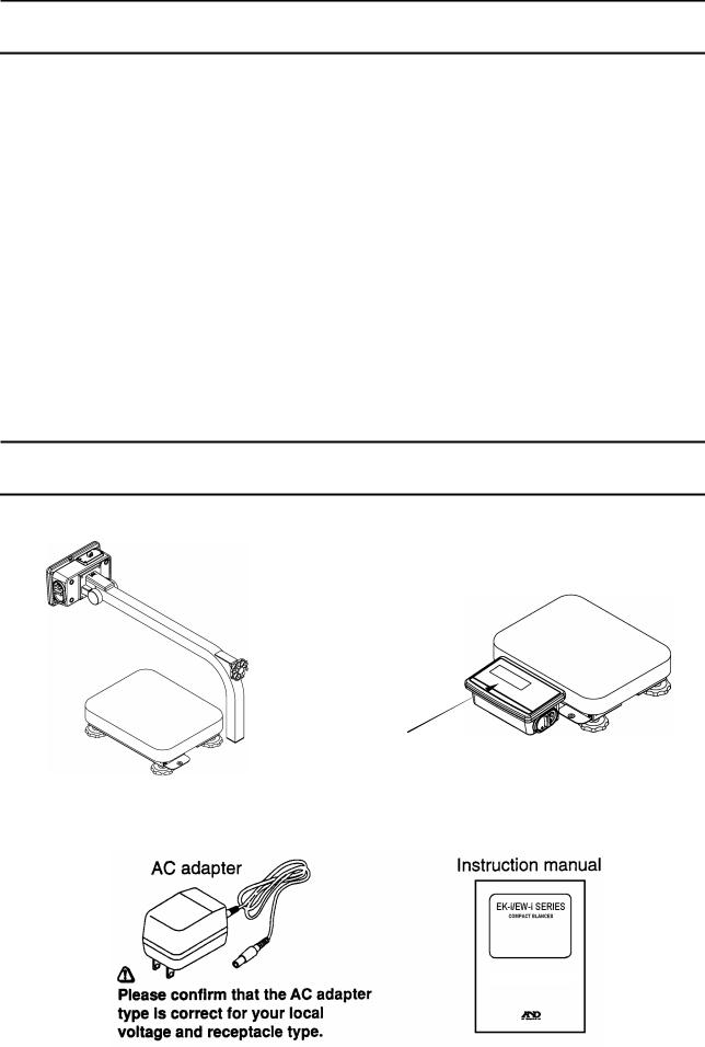
2. UNPACKING
When unpacking, check whether all of the following items are included:
FG30KAM/60KAM/150KAM
FG60KAL/150KAL
Column support foot
 (FG-KAM only)
Protective cover is attached. (All models)
Scale (Shape is different by model.)
FG series
INSTRUCTION MANUAL
2

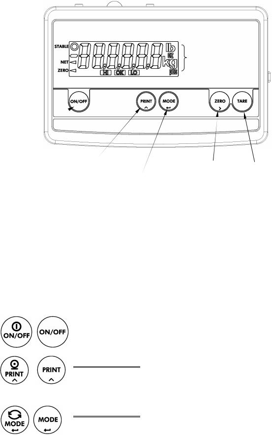
3. NAMES AND FUNCTIONS
Display pod
Display |
|
Battery |
|
cover |
|
column |
|
|
|
|
|
|
|
|
AC adapter jack
Weighing pan
Column support foot
 (FG-KAM only)
Option slot
(Bottom)
CAL switch cover
Cable cover
(FG-KAL/KAM)
|
|
|
|
|
|
|
|
Spirit level |
|
|
|
|
|
|
|||
|
|
|
|
|
|
|
|
|
|
|
|
|
|
|
|
|
|
|
|
|
|
|
|
|
Base |
|
|
|
|
|
|||||
|
|
|
|
|
|
|
|
|
|
|
|
|
|
|
|||
|
|
|
|
|
|
|
Leveling foot |
Spirit level |
|
|
|
||||||
|
|
|
|
|
|
|
|
|
|
|
|
|
|
|
|
||
|
|
|
|
|
|
|
|
|
|
|
|
|
|
|
|
||
|
|
|
FG-KAL/KAM series |
|
FG-KBM series |
||||||||||||
|
|
|
|
|
|
||||||||||||
Metric models |
|
|
|
|
|
||||||||||||
|
|
|
LCD display |
|
|
|
|
|
|||||||||
|
|
|
|
|
|
|
|
|
|
|
|
|
|
|
|
|
|
|
|
STABLE indicator |
|
|
|
|
|
||||||||||
|
|
|
|
|
|
|
|
|
|
|
|
|
|
|
|
|
|
|
|
|
NET indicator |
|
|
Weighing unit |
|||||||||||
|
|
ZERO indicator |
|
|
|||||||||||||
|
|
|
|
|
|
|
|||||||||||
HI OK LO indicator |
|
|
|
|
|
||||||||||||
|
|
ON/OFF switch |
|
|
|
|
|
||||||||||
|
|
|
|
PRINT switch |
|
|
|
|
|||||||||
|
|
|
|
|
RE-ZERO switch |
||||||||||||
|
|
|
|
|
|
|
|
MODE switch |
|
|
|
|
|
||||
3
U.S.A. models
Weighing unit
ON/OFF switch |
|
|
|
|
||||||
|
|
|
|
|
|
|
|
|
|
|
|
|
|
|
|
|
PRINT switch |
|
TARE switch |
||
|
|
|
|
|
|
|
ZERO switch |
|||
|
|
|
|
|
|
|
MODE switch |
|
|
|
Indicators |
|
|
|
|
||||||
STABLE ? |
Indicates when the reading is stable. |
|
||||||||
NET ? |
Indicates when NET weight is displayed. (Tare function is used.) |
|||||||||
ZERO ? |
Indicates when the scale zero is correct. |
|
||||||||
|
|
|
|
|
|
|
|
|
|
|
|
HI |
|
OK |
|
|
LO |
Indicates when the scale zero is correct. |
|
||
Weighing units |
“kg” and “pcs” for metric models |
|
||||||||
|
|
|
|
|
|
|
“lb”, “oz”, “kg” and “pcs” for U.S.A. models |
|
||
Switches
ON/OFF Switch
Used to turn the power on or off. When turned on, the scale will be automatically set to zero (power-on zero).
PRINT Switch
Outputs the weight value to printer. In the setting mode, this switch is used to increment the value of the selected digit blinking.
MODE Switch
Switches the weighing unit. In the setting mode, this switch is used to store a parameter and go to the next.
4
RE-ZERO Switch
Clears the display to zero. In the setting mode, this switch is used to select a digit blinking to change its value.
ZERO Switch U.S.A. model
Zeroes the scale and turns the display zero. In the setting mode, this switch is used to select a digit blinking to change its value.
TARE Switch U.S.A. model
Subtracts tare (container) weight on the weighing pan.
? The |
RE-ZERO |
, |
ZERO |
and |
|
TARE |
switches work when the weight value is |
|||
stable. |
|
|
|
|
|
|
|
|
|
|
? The |
|
and |
|
|
switches will zero the scale if the weight is within |
|||||
RE-ZERO |
ZERO |
|||||||||
±2% of the weighing capacity (kg) around the power-on zero point. The ZERO indicator ? turns on.
? If the weight exceeds +2% of the weighing capacity (kg), the RE-ZERO switch will tare the scale. In this case the ZERO and NET indicators turn on.
? The TARE switch will tare the scale when the weight is plus value. In this case the ZERO and NET indicators turn on.
?The ZERO operation clears tare operation previously done and NET indicator turns off.
5
4. SETTING UP
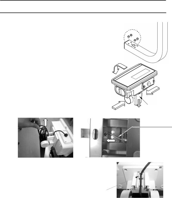
4-1. Attaching a display pod to the base (FG-KAL and FG-KAM)
1.First, remove the 4 screws from the bottom of the display column.
2.Set the display column to the base by pulling the cable into the base.
? Take care not pinch the cable between the column and the base.
3. Tighten the 4 screws removed at step 1 to fix the display column firmly.
4. Tilt the display pod forward by pressing in on the two round side clamps, and slide off the cable cover.
5. Pull the bundle of cable out from the top end of display column, feeding all of slack of the cable on the base into the display column.
? Take care not scratch the cable.
Screws
Cable cover
Cable
Neither slack
Nor tension
6.Put the bundle of cable back into the display column.
7.Make sure the cable is fitted to the 2 cable guides and attach the cable cover.
Cable guide
8. Place the weighing pan on the base.
4-2. Installing the scale
1.Select the place for installing the scale. Refer to “Cautions for installing the scale” below.
2.Adjust the level of the base, using the spirit level and leveling feet. The FG-KAM has an extra foot under the display column. Adjust this foot to reach floor after adjusting the level of the base.
3.Tilt the display pod by pressing in on the two round side clamps.
6

Cautions for installing the scale
Consider the following conditions to get the most out of your scale.
?Install the scale where the temperature and relative humidity is stable. There is no draft and a stable power source is available.
?Install the scale on a solid and level surface.
?Do not install the scale in direct sunlight.
?Do not install the scale near heaters or air conditioners.
?Do not install the scale where there is flammable or corrosive gas present.
?Do not install the scale near equipment which produces magnetic fields.
?Do not install the scale where there is apt to be static electricity, in a place where the relative humidity is lower than 45% RH. Plastic and isolators are apt to be charged with static electricity.
?Do not use an unstable power source.
?When the scale is installed for the first time, or the scale has been moved, carry out calibration as described in “8. CALIBRATION”.
4-3. Power source
For the power source, the AC adapter or C size dry cells can be used.
When using the AC adapter
Use a stable power source. To use the AC adapter, insert the AC adapter plug into the AC adapter jack on the rear side of display pod.
 ? Confirm the AC adapter type is correct for your local voltage.
When using the batteries
Prepare 4 x C size (R14P/LR14) dry batteries. The batteries are not included in the product. The scale can be used continuously for about 150 hours using the alkaline batteries.
1.Turn of the scale and disconnect the AC adapter if used.
2.Slide the battery cover off
3.Push the battery case inside the display pod and take it out.
4.Insert four new dry cells into the battery case.
5.Push the battery case into the display pod as before.
6.Attach the battery cover.
 ? Take great care of the polarity of batteries. The polarity marks are shown in the battery case.
?Replace used batteries with four new ones when “lb0” is displayed.
?Do not mix used and new batteries. It may cause damage to the battery or product, if used.
?Do not mix the battery type. It may cause damage to the battery or product.
?The battery life depends on the ambient temperature.
?Remove batteries from display pod when the scale is not to be used for a long time. They may leak and cause damage.
?Damage due to battery leakage is not covered by the warranty.
7

5. BASIC OPERATION
5-1. Turning the power ON and OFF
1. Press the ON/OFF switch to turn the power ON.
All the display symbols are displayed and the scale waits for the weighing data to become stable.
(Only the units available illuminate.)
After the weighing value internally becomes stable, the display turns off for a moment and zero is shown with the ZERO indicator (power-on zero).
If the weighing value is unstable, the display shows “------”. Check if anything touches the weighing pan, or check if there is strong wind or vibration.
The range for power-on zero is within ±10% of the weighing capacity (kg) around the calibrated zero point.
If the power is switched ON while there is a load beyond this range, the scale shows “------”. Remove the load on the weighing pan.
2. Pressing the ON/OFF switch again, and the power will be switched OFF.
?Auto power-off function
It is possible to have the power automatically switched OFF, if zero is displayed for approximately 5 minutes. See “9-2. Function list” and set the function “F1-1” or “F1- 2” .
5-2. Selecting a weighing unit
Press the MODE switch to select a weighing unit.
lb oz kg pcs
?“lb” and “oz” will be available for U.S.A. models only.
?For U.S.A. models, it is possible to specify the display unit “lb”, ”oz” or ”kg” that will shown first when the power is switched on. See “Function list F3”.
5-3. Basic operation
1. Turn the display on via the ON/OFF switch.
2. Select a weighing unit using the MODE switch.
3. When the display doesn’t show zero, press the RE-ZERO ( ZERO ) switch to set the display to zero.
4. When using a tare (container), place the container on the weighing pan, and press the RE-ZERO ( TARE ) switch to set the display to zero.
5. Place the object to be weighed on the pan or in the container, and wait for the STABLE indicator to be displayed and read the value.
8
 Loading...