


A&D HW-200KGL, HW-100KGL, HW-10KGL, HG-60KGV, HW-10KGV User Manual
...HW-G Series
Digital Platform Scales
Instruction Manual
0Z1M v1a
HW-10KGL HW-10KGV HW-60KGL HW-60KGV HW-100KGL HW100KGV HW-200KGL HW-200KGV

Contents
1 |
Compliance ........................................................................................ |
3 |
1.1 |
Compliance with FCC rules ........................................................... |
3 |
2 |
Outline and Features ......................................................................... |
4 |
3 |
Unpacking .......................................................................................... |
5 |
3.1 |
Accessories and Options list ......................................................... |
6 |
4 |
Caution .............................................................................................. |
8 |
4.1 |
Precautions for Installing the Scale ............................................... |
8 |
4.2 |
Precautions for Operating the Scale .............................................. |
8 |
4.3 |
Precautions for Storing the Scale .................................................. |
8 |
5 |
Installing the Scale ............................................................................. |
9 |
5.1 |
Installing the batteries for Type L ................................................ |
11 |
6 |
Names ............................................................................................. |
12 |
6.1 |
Display and Symbols ................................................................... |
13 |
6.2 |
Switches ...................................................................................... |
15 |
7 |
Basic Operation ............................................................................... |
17 |
7.1 |
Turning the Scale on/off and Weighing ....................................... |
17 |
7.1.1 |
Type V or Type L with AC adaptor .......................................... |
17 |
7.1.2 |
Type L with Batteries ............................................................... |
18 |
7.2 |
Tare (and Net Display)................................................................. |
19 |
7.2.1 |
Semi-Automatic Tare (Input by Weighing) ............................... |
19 |
7.2.2 |
Preset Tare (Digital Input of Known Tare) ............................... |
19 |
7.3 |
Mode Switch (Changing Unit and Mode) ..................................... |
20 |
8 |
Counting Mode ............................................................................... |
21 |
8.1 |
Storing a Unit Mass ..................................................................... |
21 |
8.2 |
Counting the number of articles ................................................... |
22 |
9 |
Percentage Mode ............................................................................ |
23 |
9.1 |
Storing a 100% Mass .................................................................. |
23 |
9.2 |
Reading Percentage .................................................................... |
24 |
10 |
Accumulation Function..................................................................... |
25 |
10.1 |
Preparation (Setting Parameters) ................................................ |
26 |
10.2 |
Operation and Performance (Examples) ..................................... |
27 |
11 |
Comparator Function ........................................................................ |
28 |
11.1 |
Preparation (Setting Parameters) ................................................ |
29 |
11.2 |
Operation and Performance (Examples) ..................................... |
31 |
12. |
Full/Dribble Batch Function .............................................................. |
32 |
12.1 |
Preparation (Setting Parameters) ................................................ |
34 |
13. |
Simple Batch Function ..................................................................... |
36 |
13.1 |
Preparation (Setting Parameters) ................................................ |
37 |
13.2 |
Operation and Performance (Examples) ..................................... |
38 |
HW-G Instruction Manual Page 1
HW-G OZIM v1a
14 |
Calibration (Adjusting the Scale)...................................................... |
39 |
|
|
14.1 |
The Gravity Acceleration Table ................................................... |
40 |
|
14.2 |
The Complete Calibration Procedure .......................................... |
41 |
|
14.2.1 |
Gravity Acceleration Correction ............................................... |
41 |
|
14.2.2 |
Preparation .............................................................................. |
41 |
|
14.2.3 |
Calibration of the Zero Point .................................................... |
42 |
|
14.2.4 |
Span Calibration ...................................................................... |
42 |
15 |
The Function Table .......................................................................... |
43 |
|
|
15.1 |
The Procedure for Setting Parameters ........................................ |
43 |
|
15.2 |
Parameter List ............................................................................. |
44 |
16 |
RS-232C Serial Interface ................................................................. |
48 |
|
|
16.1 |
Data Format ................................................................................. |
49 |
|
16.2 |
Stream Mode ............................................................................... |
51 |
|
16.2.1 |
Preparation and Performance (Examples) .............................. |
51 |
|
16.3 |
Command mode .......................................................................... |
52 |
|
16.3.1 |
Command List ......................................................................... |
52 |
|
16.4 |
Preparation (Setting Parameters) ................................................ |
55 |
17 |
Options ............................................................................................ |
56 |
|
|
17.1 |
RS-232C/ Relay output/ Buzzer (OP-03) ..................................... |
56 |
|
17.2 |
RS-422/ RS-485 / Relay output (OP-04) ..................................... |
57 |
|
17.2.1 |
Communication Format ........................................................... |
59 |
|
17.2.2 |
Command List ......................................................................... |
59 |
|
17.3 |
Internal Printer for Type V (OP-06) .............................................. |
62 |
18 |
Specifications ................................................................................... |
65 |
|
19 |
Maintenance .................................................................................... |
68 |
|
|
19.1 |
Repair .......................................................................................... |
68 |
|
19.2 |
Check points Before Calling Maintenance ................................... |
68 |
HW-G OZIM v1a
HW-G Instruction Manual Page 2


 1 Compliance
1.1 Compliance with FCC rules
Please note that this equipment generates, uses and can radiate radio frequency energy. This equipment has been tested and has been found to comply with the limits of a Class A computing device pursuant to Sub-part J of Part 15 of FCC rules. These rules are designed to provide reasonable protection against interference when this equipment is operated in a commercial environment. If this unit is operated in a residential area it might cause some interference and under these circumstances the user would be required to take, at his own expense, whatever measures are necessary to eliminate the interference.
(FCC = Federal Communications Commission in the U.S.A.)
HW-G Instruction Manual Page 3
HW-G OZIM v1a

2 Outline and Features
The HW-G series is a platform scale with a minimum resolution of 1/10000 .
Type L scales have an LCD (Liquid Crystal Display) and use batteries as a power source to provide portability. This type can also use an AC mains adaptor.
Type V scales have a fluorescent display so the weighing value can be read in dim light. This type uses the AC power line as a power source.
The base unit (platform) is water-resistant in accordance with IP-65 specifications.
The counting mode function converts the total mass value (total weight) of articles to a count, assuming all items to have the same mass.
The percentage mode function displays the mass of an item as a percentage of a stored 100% mass.
The accumulation function accumulates each weighing value and counts the number of weighings.
The comparator function compares the display value with the upper limit value (HI) and the lower limit value (LO) and displays the result. The result can output if option OP-03 is installed.
The simple batch function or full/dribble batch function can be used for filling to a target mass value. The status of a weighing value can be output if option OP-03 or OP-04 is installed. The outputs are Zero Band, Preliminary and Final.
The optional RS-422/RS-485 serial interface can control up to 16 scales from a computer when this option is installed in place of the standard RS-232C serial interface.
Type V scales can be equipped with option OP-06, a built-in impact dot matrix printer.
HW-G OZIM v1a
HW-G Instruction Manual Page 4


 3 Unpacking
Products
HW-10KGL
HW-10KGV
Caution 
Do not pull the load-cell cable.
Products |
Display Uint |
HW-100KGL HW-100KGV |
|
HW-200KGL HW-200KGV |
|
Pan
Base Unit
Caution
Do not pull the load-cell cable.
Display Unit
Products
HW-60KGL HW-60KGV
Pan
Base Unit 
Caution
Do not pull the load-cell cable.
All Accessories
Refer to the accessries on page 6. The combination of accessories depends upon the model.
AC Adaptor
Please confirm that the AC adaptor type is correct for your local voltage and receptacle type.
Display unit cover 14:3003217
5mm allen wrench
HW-G Instruction Manual Page 5
HW-G OZIM v1a


 3.1 Accessories and Options list
Accessories for HW-G series
Type |
Products |
Accessories |
|
HW-10KGV |
Display unit cover |
|
|
Instruction manual |
Type V |
HW-60KGV |
Display unit cover |
|
HW-100KGV |
5mm Allen wrench |
|
HW-200KGV |
Instruction manual |
|
HW-10KGL |
Display unit cover |
|
|
AC adaptor |
|
|
Instruction manual |
Type L |
HW-60KGL |
Display unit cover |
|
HW-100KGL |
5mm Allen wrench |
|
HW-200KGL |
AC adaptor |
|
|
Instruction manual |
|
|
|
HW-G OZIM v1a
HW-G Instruction Manual Page 6
Options List
|
Order code or option name |
Accessories |
|
|
|
OP-03 |
RS232C interface / Relay output / Buzzer |
Connector JA:TCP0586 |
|
|
|
OP-04 |
RS422/485 interface / Relay output |
Connector TM:BLA9 |
|
|
AC adaptor |
|
|
|
OP-06 |
Built-in printer for type V |
Paper PP156 |
|
|
Ink ribbon ERC-05 |
|
|
|
|
|
|
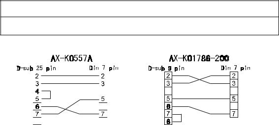
AX-K0557A RS232C cable, D-sub 25 pin, 2m |
|
|
|
|
|
AX-KO1786-200 RS232C cable, D-sub 9 pin, 2m |
|
|
|
|
|
Consumables
AX-PP156-S Special roll paper (10 rolls in a set)
AX-ERC-05-S Ink ribbon (5 ribbons in a set)
HW-G Instruction Manual Page 7
HW-G OZIM v1a

 4 Caution
4.1 Precautions for Installing the Scale
Consider the following conditions to get the most from your scale.
The best operation is where the temperature and relative humidity are stable, the scale is installed on a solid floor or bench and there is no draft.
Do not install the scale in direct sunlight.
Do not install the scale near heaters or air conditioners.
Do not install the scale where there is flammable or corrosive gas present. Do not install the scale near equipment which produces magnetic fields.
Do not install the scale where there is likely to be static electricity discharges in a place where the relative humidity is lower than 45%RH. Plastic and isolators are likely to be charged with static electricity.
The display unit is not water resistant. Use the display unit cover to avoid damage.
Do not use an unstable power source.
4.2 Precautions for Operating the Scale
Periodically check the scale with a known weight.
Calibrate the scale before using it and after moving it to another location.
Do not place anything on the pan which is heavier than the weighing capacity
Do not drop anything onto the pan.
Do not use a sharp instrument such as a pencil or ball-point pen to press the switches. Press the switches gently using only your finger.
We recommend pressing the ZERO or TARE switch before each weighing to prevent possible error.
Replace used dry cells with six new ones when the BATT symbol is displayed. Dry cell (battery) is size D.
4.3 Precautions for Storing the Scale
Do not disassemble the scale.
Do not use solvents to clean the scale.
For best cleaning of the display unit, wipe with a dry lint free cloth or a lint free cloth which is moistened with warm water and a mild detergent.
The base unit can be cleaned with gentle water jets while brushing the base unit.
Weigh only after the unit is dry.
Protect the display unit from dust and water by using the vinyl cover.
Remove batteries from display unit when the scale is not in use for a long time. If you leave the batteries installed they may leak and damage the scale.
HW-G OZIM v1a
HW-G Instruction Manual Page 8

 5 Installing the Scale
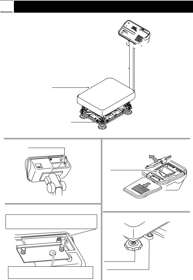
This procedure includes all of the steps for installing the HW-G series scales
Step 1 Unpacking
Remove the weighing pan from the carton and place to one side. Remove the base unit and column from the carton, taking care not to pull on the loadcell cable.
Step 2 Secure the Column
Step 2a Remove the 4 Allen screws from the column lower bracket.
Step 2b Pull the excess loadcell cable through the column as you position the column to the base unit, so as not to damage the loadcell cable. Affix the column to the base unit using four 5mm Allen screws.
Stpe 3 Secure the Display Unit
Step 3a Remove the 2 screws from the rear of the display unit, position the display unit onto the column bracket and pull the excess cable back down the centre of the column to the base unit. Ensure that the cable exits via the cut out in the display unit column bracket and secure the headwork with the 2 screws.
Step 3b Carefully make the connection between the cable connector and J1 inside the headwork, then secure the rear display panel.
Column
Step 2a
Step 1
Base unit |
Load-cell cable |
Step 2b 5mm allen screws
Allen wrench
Step 3
Screws
Step 4 Fit the Pan |
Step 4 |
Step 4 Fold the excess cable at the |
basework end and secure with the ‘twist andTie excess cable here tie’ strip provided.
Fit the pan to the base unit.
HW-G Instruction Manual Page 9
HW-G OZIM v1a
Select the place where you intend to instal the scale. Consider “4. Caution” on page 8.
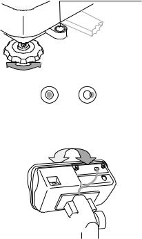
Step 5 Level the Scale
Level the base unit by using the “Bubble spirit level” and “Levelling feet”.
Step 6 Adjust the Display Unit
Press the caps at the pole top from both sides and adjust the angle of the display unit.
Step 7 Connect the Power
Install the batteries (see page 11) or connect the AC adaptor or mains cable. Check the weighing accuracy. If the scale needs calibration, refer to “14 Calibration”.
Bubble spirit level
Leveling foot
Step 5
OK NG
Step 6 

HW-G OZIM v1a
HW-G Instruction Manual Page 10
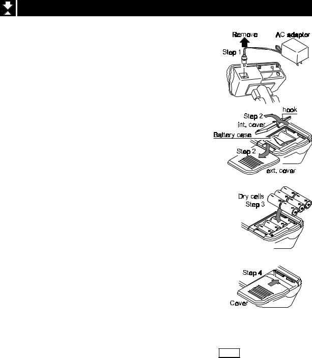
5.1 Installing the Batteries for Type L
Step 1 If necessary turn off the display and remove the AC adaptor.
Step 2 Press and slide downwards to remove the external cover.
Press the hook of the internal cover to the left side and lift off the cover.
Step 3 Insert six new dry cells ensuring correct polarity (+,-). Battery size is ‘D’.
Step 4 Replace the covers removed in step 2.
Caution
Replace used dry cells with six new ones, when BATT is displayed.
Do not mix used and new batteries. It may cause damage to the battery or product.
Check the polarity when installing the batteries. If you do not observe this it may cause battery leakage. Also if the polarity of a battery is wrong the scale may only work temporarily.
The battery life is dependent upon the environmental temperature. Remove batteries from the display unit when the scale is not to be used for a long time. They may leak and cause damage.
Damage which is due to battery leakage is not covered under warranty.
HW-G Instruction Manual Page 11
HW-G OZIM v1a

 6 Names
Display unit 
 Angle adjustment


Column
Weigh pan
Base unit
RS-232C Interface connector
CAL switch
Calibrating the scale to weigh it correctly.
Caution
It is necessary to use classified mass.
Type L
Battery Case
Leveling Foot
Bubble Spirit Level
HW-G OZIM v1a
HW-G Instruction Manual Page 12
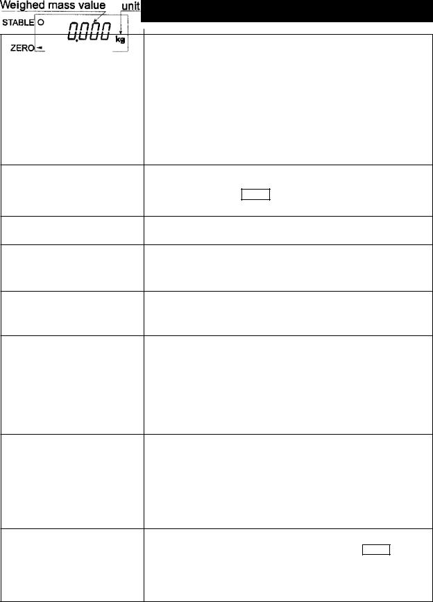
6.1 Display and Symbols
Display and Symbols |
Meaning |
||||
|
Stability mark. |
|
|||
|
When the current weight value is not changing, this mark |
||||
|
is displayed. The reading may now be taken. |
||||
|
|
|
|
|
|
|
Zero point mark. |
|
|||
|
With nothing |
on the pan and pressing the |
|||
|
|
|
|
switch or with a mass on the pan and pressing the |
|
|
|
ZERO |
|||
|
|
switch, this mark is displayed. The zero point is the |
|||
|
TARE |
||||
|
starting point to weighing. |
||||
Net mark.
After pressing the TARE switch this mark is displayed to show net weight is displayed
Preset tare mark.
When storing a tare with digital input this mark blinks.
Accumulation mark.
When using the accumulation function, this mark is displayed.
Low battery mark for type L.
When the battery power is low this mark is displayed.
Replace with six new batteries.
Ready mark for the full/dribble batch function. This mark shows:
ON
OFF
Blinking
The comparator indicator.
Using the comparator function and comparing a weighing value with the upper and lower limits, the result is indicated.
Using the full/dribble batch function, the full flow gate indicator is shown as OK, the dribble flow gate indicator as HI and the zero band indicator as LO.
Example:- Display of zero (zero point).
With an empty weighing pan by pressing the ZERO switch:-
The Zero mark is displayed.
The stability mark is displayed.
HW-G Instruction Manual Page 13
HW-G OZIM v1a
Display and Symbols |
Meaning |
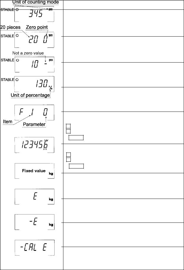
Example:- Display of the counting mode.
This mode uses the registered unit mass, counts the quantity of articles on the pan. The unit is PCS.
Example:- Storing the unit mass in the counting mode.
This is a display of zero point for counting mode and uses
20 pieces for the unit mass registration.
Example:- Storing the unit mass in the counting mode.
Sign “-” means “weighing value is not zero”.
Sample number is 10 pieces.
Example:- Percentage mode.
This mode uses the registered 100% mass, converts the weighing value to a percentage. The unit is % .
Example:- Display of the function table.
This function table sets parameters of items.
< switch |
Selecting an item. |
^ switch |
Selecting a parameter of the item. |
ENTER switch Storing new parameters.
Example:-. Preset tare. Entering tare with digital input.
< switch |
Selecting a figure. |
^ switch |
Selecting a number. |
ENTER switch Storing new tare.
Example:- Hold display
The hold display is set using f12 of the function table.
When weighing value is “near-zero” or changes more than 25% +30 digits, the hold is cancelled.
Overload display.
Remove everything from the pan.
Weighing error.
Check the base unit and weighing pan.
Calibration error.
Means “Calibration mass is too light”.
Check the base unit and weighing pan.
HW-G OZIM v1a
HW-G Instruction Manual Page 14
Displays and Symbols |
Meaning |
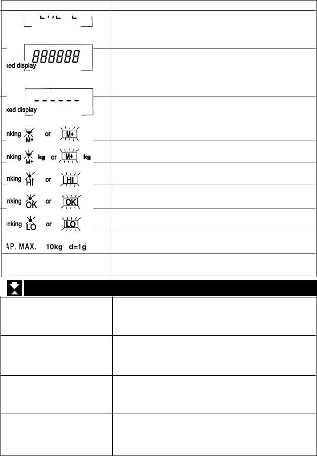
Calibration error.
Means “Calibration mass is too heavy”.
Check the base unit and weighing pan.
Weighed value is unstable due to drift, vibration etc. when turning on the scale.
Check around the weighing pan.
Check the connection of the load cell cable.
Remove everything from the weighing pan.
Check around weighing pan.
Perform zero point calibration of the scale.
Accumulated data count
Total mass value of the accumulated data.
Comparator function = display is an upper limit.
Full/dribble batch function = display is a final value.
Full/dribble batch function = display is a preliminary value.
Comparator function = display is a lower limit.
Full/dribble batch function = display is the zero band.
Description of the weighing capacity and minimum graduation.
6.2 Switches
Power switch.
Note Type V is in standby status when power is connected.
Zero switch.
When there is nothing on the pan and the ZERO switch is pressed, the scale displays zero and the zero point mark.
Any stored tare is cancelled.
Tare switch.
Used to store the weight of a container when carrying out net weighing.
Sample switch.
Storing the unit mass it is used to select a sample number.
In the function table it is used to select a parameter.
HW-G Instruction Manual Page 15
HW-G OZIM v1a
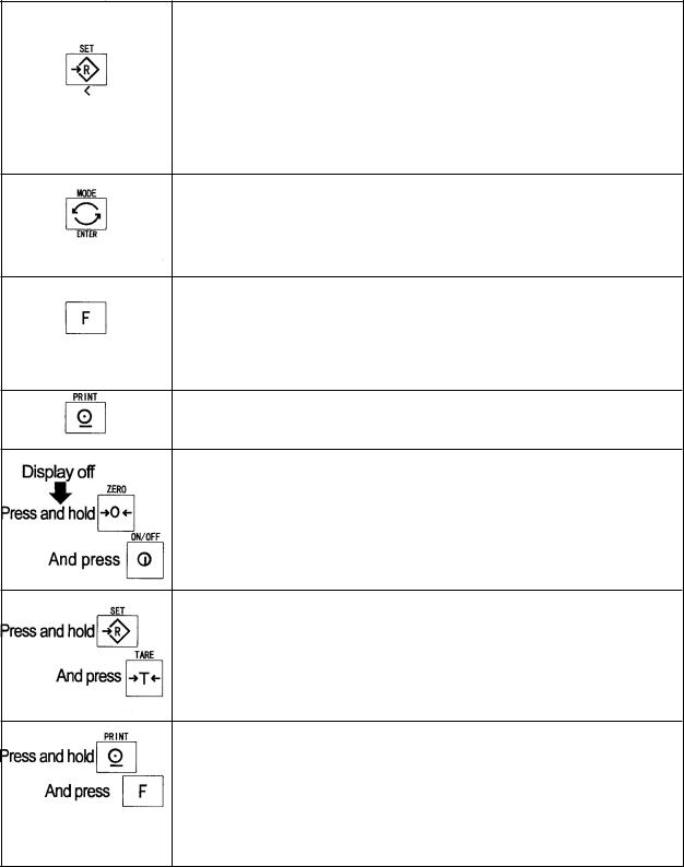
Set switch.
Can be used to turn the comparator on/off. (Refer to f6 ) Counting mode, it is used to enter the mode to store the unit mass.
Percentage mode, it is used to enter the mode to store the 100% mass.
In the full/dribble batch function, it is used as a start switch.
In the preset tare, and selecting calibration mass, it is used to select a figure.
Mode switch.
Used to change the current unit.
While setting modes, this switch is used for “storing a parameter and proceeding the next step”.
F switch
Full/dribble batch function it is used to finish the process. (Refer to f10 )
Hold switch. (Refer to f12 )
Setting a preset tare, selects polarity (+,-).
Print switch.
Used to print or output data. (Refer to f5, f9 )
Used to enter the function table
Used to enter the mode to set a preset tare
Used to perform paper feed for the optional printer for type V.
HW-G OZIM v1a
HW-G Instruction Manual Page 16


 7 Basic Operation


 7.1 Turning the Scale On/Off & Basic Weighing
7.1.1 Type V or Type L with AC adaptor
Step |
1 |
Ensure that the pan is empty. |
||||||
Step |
2 |
Confirm that local voltage and receptacle type match your scale. |
||||||
Step |
3 |
The scale turns on/off using the |
|
|
switch alternately. |
|||
ON/OFF |
||||||||
Step |
4 |
Check the accuracy of weighing. If you calibrate the scale, perform it after |
||||||
|
|
allowing the scale to warm up for 30 minutes. |
||||||
Step |
5 |
Press the |
|
switch to display zero. (With nothing on the pan.) |
||||
ZERO |
||||||||
Step |
6 |
Place something gently onto the pan. |
||||||
Step |
7 |
You can read the weight after the stability mark is displayed. |
||||||
Step |
8 |
Remove the item from the pan. |
||||||
Step |
9 |
Turn the scale off using the |
|
|
switch. |
|||
ON/OFF |
||||||||
Memo
With the power cord connected, type V consumes only sufficient power for standby status after turning off the scale.
With the AC adaptor connected, type L consumes only the power of the AC adaptor after turning off the scale.
HW-G Instruction Manual Page 17
HW-G OZIM v1a

7.1.2 Type L with Batteries
Step |
1 |
Install six new batteries. Refer to “5.1. Installing the batteries for Type L”. |
||||||
Step |
2 |
Ensure that the pan is empty. |
||||||
Step |
3 |
The scale turns on/off using the |
|
|
switch alternately. |
|||
ON/OFF |
||||||||
Step |
4 |
Check the accuracy of weighing. If you calibrate the scale, perform it after |
||||||
|
|
warming up the scale for 30 minutes. You will need to disable the auto power |
||||||
|
|
off function. See 15.2 page 43. |
||||||
Step |
5 |
Press the |
|
switch to display zero. (With nothing on the pan.) |
||||
ZERO |
||||||||
Step |
6 |
Gently place something on the pan. |
||||||
Step |
7 |
You can read the weight value after the stability mark is displayed. |
||||||
Step |
8 |
Remove the item from the pan. |
||||||
Step |
9 |
Turn the scale off using the |
|
|
switch. |
|||
ON/OFF |
||||||||
Caution
Replace used dry cells with six new ones when BATT is displayed. Battery life is affected by the environmental temperature.
Remove batteries from the display unit when the scale is not to be used for a long time. The batteries may leak and cause damage.
HW-G OZIM v1a
HW-G Instruction Manual Page 18


 7.2 Tare (and Net Display)
The “Tare” is used to cancel the mass of a container, receptacle, case, bag, etc. which is put on the pan to contain the item to be weighed.
Caution
The tare reduces the available weighing range.
The current tare value is reset by pressing the ZERO switch when the pan is empty, or by turning the scale off. (Reset value is zero.)
7.2.1 Semi-Automatic Tare (Input by Weighing)
Step 1 Put the container onto the pan.
Step |
2 |
Press the |
TARE |
switch. The display becomes zero and the net mark |
|
|
is displayed. |
|
|
Step |
3 |
It is now possible to put something into the container and to read its |
||
|
|
net display. |
||
Step |
4 |
Remove all items from the pan. |
||
7.2.2 Preset Tare (Digital Input of Known Tare)
Step 1 |
Press and hold the |
SET |
switch and press the |
TARE |
switch. |
|||
|
|
Then the blank or stored tare value is displayed. This blank display |
||||||
|
|
means that the tare value is zero (reset value) and |
blinks. |
|||||
Step |
2 |
Set the preset tare value by using the following switches. |
|
|||||
|
|
^ switch |
selecting the value of a digit. |
|
||||
|
|
< switch |
selecting a digit. |
|
||||
Step |
3 |
Press the ENTER switch to store the new preset tare value. |
|
|||||
|
|
The scale |
|
a net value i.e. the tare value subtracted from the |
||||
|
|
displays |
||||||
|
|
gross weight value. |
|
|||||
Step |
4 |
It is now possible to put something onto the pan and to read its net |
||||||
|
|
weight. |
|
|
|
|
|
|
Step |
5 |
Remove all items from the pan. |
|
|||||
HW-G Instruction Manual Page 19
HW-G OZIM v1a


 7.3 Mode Switch (Changing Unit & Mode)
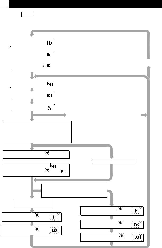
Pressing the MODE switch the display changes as shown below. Refer to the function table f3 for available units. Useable units are according to the factory settings.
|
|
If the law in your area |
|
|
|
|
|
|
Pound |
|
|
|
|
||
|
|
premits, you may use all |
|
|
|
|
|
|
|
|
|
|
|
||
|
|
of the units. Also, some |
|
|
|
|
|
|
Ounce |
|
|
|
|
||
|
dealers may initially turn |
|
|
|
|
||
|
|
|
|
|
|
||
|
|
|
|
|
|
||
|
|
off units which are not |
|
|
Non metric units |
||
|
Pound-Ounce |
|
|
||||
|
regularly used. |
|
|
|
|
||
|
|
|
|
|
|||
|
|
|
|
|
|
||
|
|
|
|
|
|
|
|
|
|
|
|
|
Metric unit |
|
|
|
|
|
|
|
|
|
|
|
|
|
|
|
|
|
|
|
Metric kg |
|
|
|
|
|
|
|
|
|
|
|
|
|
|
|
|
|
|
|
|
|
|
|
Counting Mode |
|
|
|
|
|
|
|
|
|
|
|
|
|
|
|
|
|
|
|
|
|
|
|
Percentage Made |
|
|
|
|
|
|
|
|
Inactive Comparator (f6 0) |
|
|
|||
|
|
|
and |
|
|
||
|
|
|
Inactive Accumulation Function (f8 0) |
|
|||
|
|
|
|
|
|
|
|
Either function is active.
Comparator (f6 1 ~ f6 7)
Simple Batch Function (f6 8)
Full/Dribble Batch Function (f6 9)
Accumulation Function (f8 1)
Accumulation Count M+ or 


 No Accumulation Data
Accumulation Value M+ or 
Active Simple Batch Function or Active Full/Dribble Batch Function (f6 8, f6 9)
Active Comparator
(f6 1 ~ f6 7)
Comparator |
HI |
or |
Upper limit |
||
Comparator |
LO |
or |
Lower limit |
Final value |
HI |
or |
Preliminary value |
OK |
or |
Zero band |
LO or |
|
HW-G OZIM v1a
HW-G Instruction Manual Page 20
 Loading...