


HW-200KV-WP
Waterproof Digital Platform Scale
HV-15KV-WP
HV-60KV-WP
HV-200KV-WP
HW-10KV-WP
HW-60KV-WP
HW-100KV-WP
HW-200KV-WP
1WMPD4000211B

This is a hazard alert mark.
This mark informs you about the operation of the product.
Note This manual is subject to change without notice at any time to improve the product.
No part of this manual may be photocopied, reproduced, or translated into another
language without the prior written consent of the A&D Company.
Product specifications are subject to change without any obligation on the part of the
manufacture.

Contents
1. Compliance ........................................................................ 3
1.1.1. Compliance with FCC rules....................................................... 3
1.1.2. Classification of protection provided by enclosures .................. 3
2. Outline and Features.......................................................... 4
3. Unpacking .......................................................................... 5
3.1. Accessories and Options list ......................................................... 6
4. Caution............................................................................... 7
4.1. Precautions for Installing the Scale ............................................... 7
4.2. Precautions for Operating the Scale.............................................. 7
4.3. Precautions for Storing the Scale.................................................. 7
5. Installing the Scale ............................................................. 8
5.1. Removing the pole ........................................................................ 9
5.2. Grounding the scale .................................................................... 11
6. Names.............................................................................. 12
6.1. Display and Symbols................................................................... 13
6.2. Switches...................................................................................... 15
7. Basic Operation................................................................ 17
7.1. Turing the Scale on/off and Weighing ......................................... 17
7.2. Tare (And Net Display)................................................................ 18
7.2.1. The Way of Tare Input by Weighing........................................ 18
7.2.2. The Way of Digital Input (Preset Tare).................................... 18
7.3. Weighing Range for the HV-WP series ....................................... 19
7.4. Mode Switch (Changing Unit and Mode)..................................... 20
8. Counting Mode................................................................. 22
8.1. Storing a Unit Mass ..................................................................... 22
8.2. Counting the number of articles .................................................. 23
9. Percentage Mode............................................................. 24
9.1. Storing a 100% Mass .................................................................. 24
9.2. Reading percentage .................................................................... 25
10. Accumulation Function..................................................... 26
10.1. Preparation (Setting Parameters)................................................ 27
10.2. Operation and Performance (Examples)..................................... 28
11. Upper/Lower Comparator Function.................................. 29
11.1. Preparation (Setting Parameters)................................................ 30
11.2. Operation and Performance (Examples)..................................... 32
12. Full/Dribble Batch Function .............................................. 33
HV-WP/HW-WP Series Page 1

12.1. Preparation (Setting Parameters)................................................ 35
13. Simple Batch Function ..................................................... 37
13.1. Preparation (Setting Parameters)................................................ 38
13.2. Operation and Performance (Examples)..................................... 39
14. Calibration (Adjusting the Scale)...................................... 40
14.1.1. The Gravity Acceleration Table............................................... 41
14.2. The Complete Calibration Procedure .......................................... 42
14.2.1. Gravity Acceleration Correction .............................................. 42
14.2.2. Preparation ............................................................................. 42
14.2.3. Calibration of the Zero Point ................................................... 43
14.2.4. Span Calibration ..................................................................... 43
15. The Function Table .......................................................... 44
15.1. The Procedure for Setting Parameters........................................ 44
15.2. Parameter List............................................................................. 45
16. RS-232C Serial Interface ................................................. 48
16.1. Data Format ................................................................................ 49
16.2. Stream Mode............................................................................... 51
16.2.1. Preparation and Performance (Examples) .............................. 51
16.3. Command mode.......................................................................... 52
16.3.1. Command List......................................................................... 52
16.3.2. Example of Setting Parameters .............................................. 55
17. Options............................................................................. 56
17.1. Extension cable (OP-02) ............................................................. 56
17.2. RS-232C/ Relay output/ Buzzer (OP-03)..................................... 57
17.2.1. Installing OP-03 ...................................................................... 58
17.3. RS-422/ RS-485 / Relay output (OP-04) ..................................... 59
17.3.1. Installing OP-04 ...................................................................... 60
17.3.2. Communication Format........................................................... 61
17.3.3. Command List......................................................................... 62
17.4. Roller Conveyor (OP-13, OP-14) ................................................ 64
18. Specification..................................................................... 65
19. Maintenance..................................................................... 69
19.1. Check Points Before Calling Maintenance Service ..................... 69
19.1.1. Repair ..................................................................................... 69
Page 2 HV-WP/HW-WP Series

1. Compliance
1.1.1. Compliance with FCC rules
Please note that this equipment generates, uses and can radiate radio frequency
energy. This equipment has been tested and has been found to comply with the limits
of a Class A computing device pursuant to Subpart J of Part 15 of FCC rules. These
rules are designed to provide reasonable protection against interference when this
equipment is operated in a commercial environment. If this unit is operated in a
residential area it may cause some interference and under these circumstances the
user would be required to take, at his own expense, whatever measures are
necessary to eliminate the interference.
(FCC = Federal Communications Commission in the U.S.A.)
1.1.2. Classification of protection provided by enclosures
This equipment is designed to comply with the IP Code of IEC 529.
The "IP-65" code is explained as follows:
"IP" International Protection.
"6" Against ingress of solid foreign objects.
Dust-tight. No ingress of dust.
"5" Against ingress of water with harmful effects.
Protected against water jets (no powerful jets). Water projected in jets
against the enclosure from any direction shall have no harmful effects.
Compliance with European Directive
This appliance features radio interference suppression and safety of electrical
equipment designed for certain voltage in compliance with valid EC Regulation
89/366/EEC and 73/23/EEC.
Note: The displayed value may be adversely affected under extreme electromagnetic
influences.
2. Outline and Features
HV-WP/HW-WP Series Page 3
2. Outline and Features
These scales are designed to comply with IP-65 of IEC 529
The HV-WP series is a platform scale with 1/3000 resolution, and has a "triple
weighing range" function to select the weighing range.
The HW-WP series is a platform scale with 1/10000 resolution.
The scales have a fluorescent display so the weighing value can be read in dim light.
This type uses the AC power line as a power source.
Using the standard RS-232C serial interface, data can be output to a printer, and the
scale can be controlled or can be set by a command from a personal computer.
The counting mode function converts the total mass value (total weight) of articles to
be counted, to a count, when each of these articles assume the same mass value.
The scales can display the unit of percentage.
The accumulation function accumulates each weighing value and counts the number
of weighings using six figures.
The comparator function compares the display value with the upper limit value (HI),
lower limit value (LO) and displays the result. The result can be output by a buzzer if
option OP-03 is installed.
The simple batch function or full/dribble batch function can be used for filling up to a
target mass value. The status of a weighing value can be output if option OP-03 or
OP-04 is installed. The outputs are zero band, preliminary and final.
Using the optional RS-422/RS-485 serial interface and a computer, up to 16 scales
can be controled, if this option (OP-04) is installed in place of the RS-232C serial
interface.
The following parameters are stored in the product with no power supplied.
Unit mass of the counting mode
100% mass of the percentage mode
Total count and total mass of the accumulation function
Upper limit value and lower limit value of the upper / lower comparator function,
Final value, preliminary value and zero band of the full / dribble batch function or
Final value, preliminary value and zero band of the simple batch function
Calibration data
Parameters of the function table (f1 ~ f17)
2. Outline and Features
Page 4 HV-WP/HW-WP Series
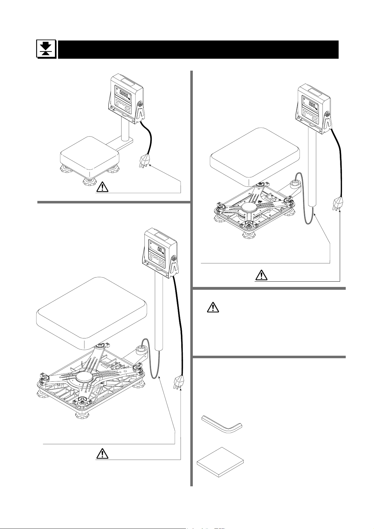
3. Unpacking
Models
HV-15KV-WP
HW-10KV-WP
Display Unit
Models
HV-60KV-WP
HW-60KV-WP
Display Unit
Pan
Base Unit
Models
HV-200KV-WP
HW-100KV-WP
HW-200KV-WP
Pan
Pan
Main power cord
Display Unit
Base Unit
Caution
Do not pull the load-cell cable.
Main power cord
Main power
Please confirm that the local
voltage and receptacle type
are correct for your scale.
All Accessories
Refer to the accessries list on the next
page. The combination of accessories is
according to the scale model.
Base Unit
Caution
Do not pull the load-cell cable.
Main power cord
3. Unpacking
HV-WP/HW-WP Series Page 5
3mm allen wrench
Instruction manual
3.1. Accessories and Options List
Accessories for the HV-WP series and HW-WP series
Models Accessories
HV-15KV-WP
HW-10KV-WP
HV-60KV-WP
HV-200KV-WP
HW-60KV-WP
HW-100KV-WP
HW-200KV-WP
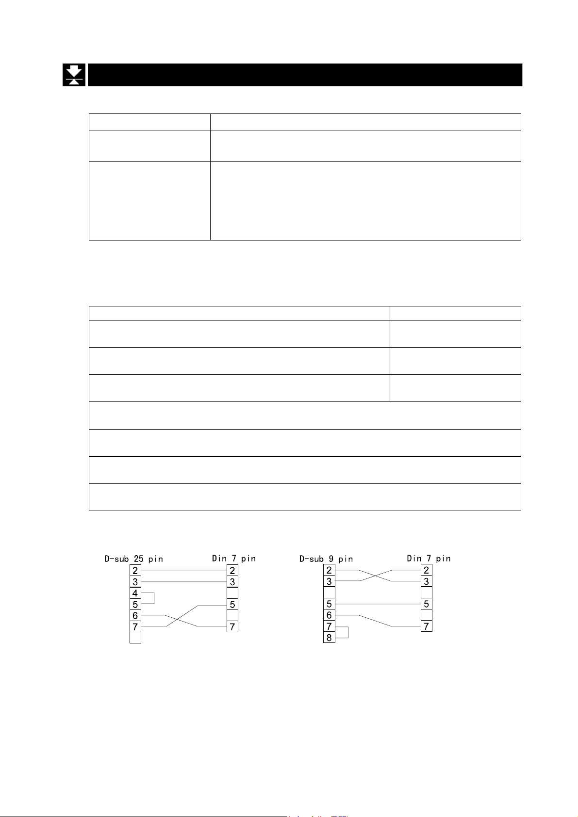
Options List
Cable or option name Accessories A
OP-02 5m extension loadcell cable Tapping screw M4x10
OP-03 RS-232C interface/ Relay output/ Buzzer Connector JA:TCP0586
OP-04 RS-422/485 interface / Relay output Connector TM:BLA9
OP-13 Roller conveyor for HV-200KV-WP, HW-100KV-WP and HW-200KV-WP
OP-14 Roller conveyor for HV-60KV-WP and HW-60KV-WP
AX-KO577A-200 RS-232C cable, D-sub 25 pin, 2m
AX-KO1786-200 RS-232C cable, D-sub 9 pin, 2m
Instruction manual
3mm Allen wrench
Instruction manual
A
A
A
A
A
A
A
A
A
A
A
A
A
AX-KO577A-200 AX-KO1786-200
3. Unpacking
Page 6 HV-WP/HW-WP Series
4. Caution
4.1. Precautions for Installing the Scale
Ground the scale, so that the user will not be subjected to an electric shock.
Do not handle the Main power cord with wet hands.
The AC plug is not water-resistant. Install it in an area where it does not get wet.
Do not install the scale where there is flammable or corrosive gas present.
Do not install the scale under water.
Do not pull, fold or arrange cables forcibly.
Consider the following conditions to get the most from your scale.
The best operation is where the temperature and relative humidity is stable, the place to
install the scale is a solid and level floor, there is no draft and the power source is stable.
Do not install the scale in direct sunlight.
Do not install the scale near heaters or air conditioners.
Do not install the scale near equipment which produces magnetic fields.
Do not install the scale in a place where it is apt to be charged with static electricity, or
where the relative humidity is lower than 45%RH. Plastic and isolators are apt to be
charged with static electricity.
Do not use an unstable power source.
4.2. Precautions for Operating the Scale
Periodically ensure that the weighing value is correct.
Calibrate the scale before using and after moving it to another location.
Do not place anything on the weighing pan which is heavier than the weighing capacity
Do not drop anything upon the weighing pan.
Do not use a sharp instrument such as a pencil or ball-point pen to press the switches.
Press the switches gently using only your finger.
We recommend pressing the ZERO switch before each weighing to prevent possible error.
Close the calibration switch cover and the display rear cover to keep waterproof.
4.3. Precautions for Storing the Scale
Do not disassemble the scale.
Do not use solvents to clean the scale.
For best cleaning of the display unit, wipe with a dry lint free cloth or a lint free cloth
which is moistened with warm water and a mild detergent.
Do not scratch the base unit with a brash.
Do not use a powerful water jet.
HV-WP/HW-WP Series Page 7
4. Caution
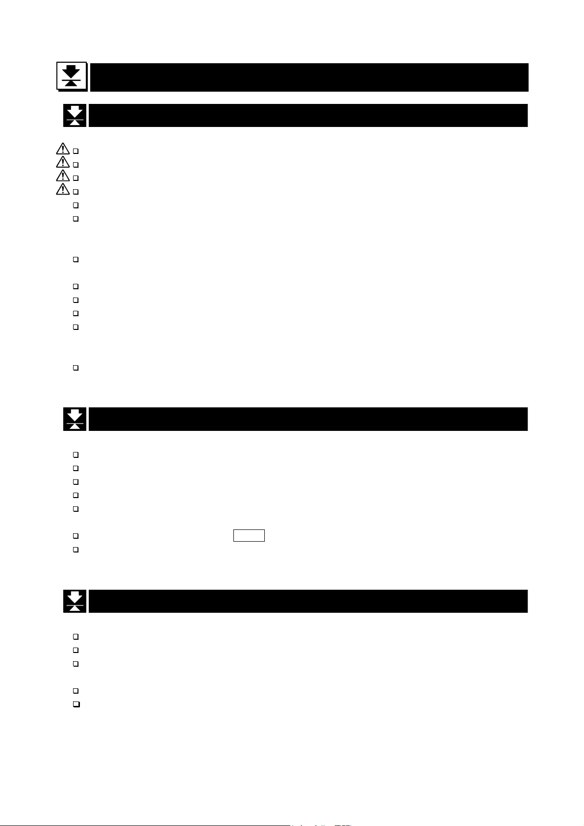
5. Installing the Scale
This procedure includes all of the steps for installing the HV-WP series and HW-WP
series. Therefore, on some models, there are some unnecessary steps.
Step 1 Connect the indicator unit to the pole with the
accesory knobs and rubber washers.
Pole
Knob
Cable
Indicator
Rubber washer
Step 2 Take the base unit and pole out, taking care
that the load-cell cable is not pulled.
Step 3 Put the weighing pan on the base unit.
Step 4 Attach the pole to the bracket of the base
unit so as not to damage the load cell cable.
Insert the remainder of the load cell cable
into the pole. Affix the pole to the bracket
using two 3mm Allen screws.
Step 5 Select the place for installing the scale. Also
consider "4. Caution" on page 7.
Step 6 Adjust the level of the base unit by using the
"Bubble spirit level" and "Leveling feet".
Step 7 Ground the scale using the earth terminal.
Pan
Step 3
Base unit
Pole
Bracket
Leveling feet
Step 6
OK NG
Power label
Pole
Step 2
Load-cell cable
Allen wrench
Step 4
3mm allen screws
Bubble spirit level
Caution
Please confirm that the local voltage and
the receptacle type are correct for your
scale.
Step 8 Adjust the angle of the indicator unit using
the knobs on the side of indicator unit.
Step 9 Check the weighing accuracy. If the scale
needs calibration, refer to "14. Calibration".
on page 40.
5. Installing the Scale
Page 8 HV-WP/HW-WP Series
Power terminals
Step7
Earth terminal
Step8
Earth
Earth
Knob
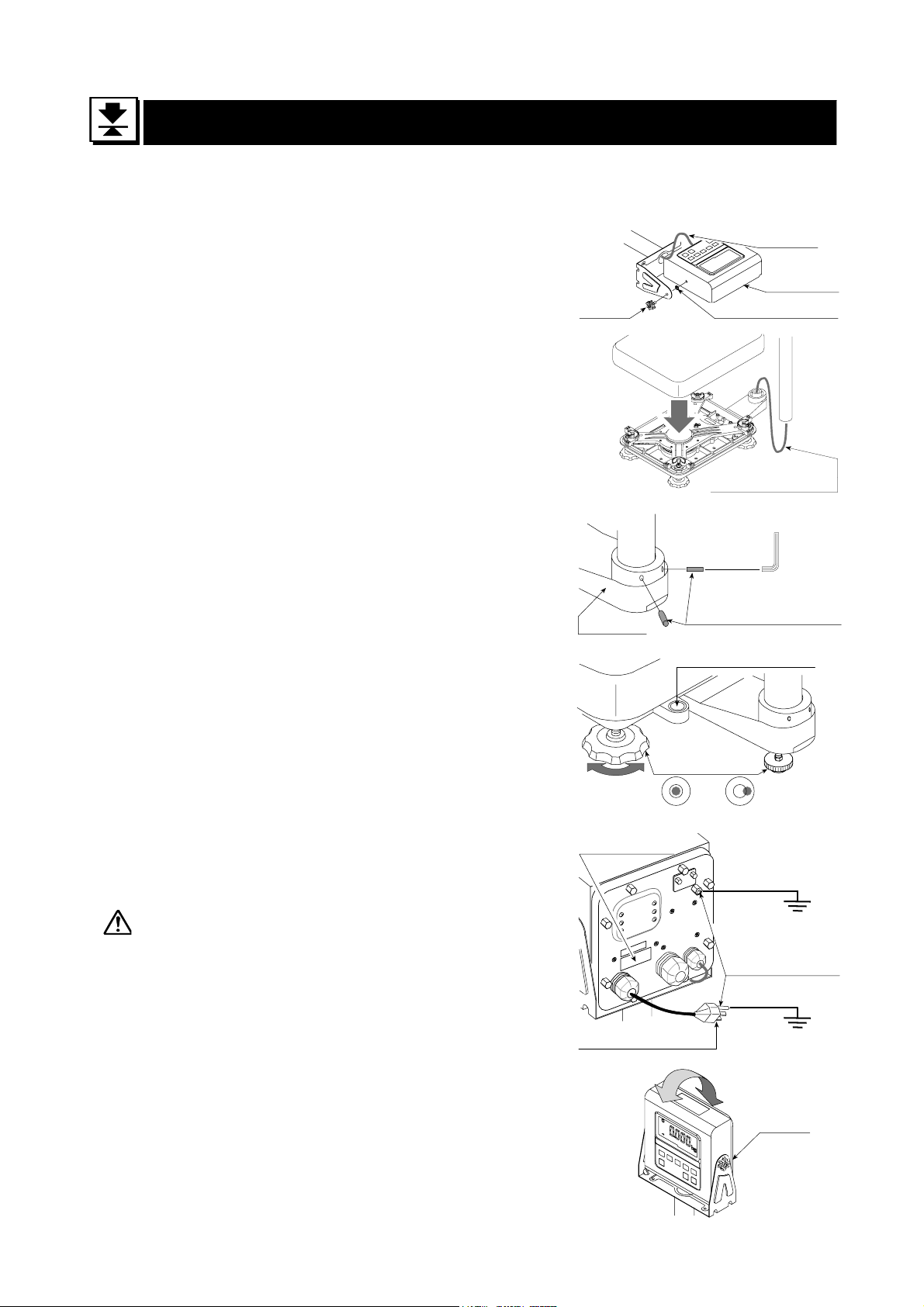
5.1. Removing the Pole
Caution
Remove the main power plug from the receptacle before removing the pole.
When removing the loadcell cable, do not pull the loadcell cable connector
forcibly and do not pull on the wires of the cable.
Do not bend the cable forcibly. Use care so that the load cell cable does not
touch the pan inside the base unit.
Avoid dust, static electricity and high humidity (or drops) because the inside
of the display unit is very sensitive.
Procedure
Step 1 Remove the power plug from the receptacle.
Step 2 Open the rear cover of the display unit.
Disconnect the loadcell cable connector gently.
Connector
Screw and O ring
Step 3 Remove the ferrite core and cable clamp from
the loadcell cable.
Step 4 Loosen the knobs to remove the display unit.
Step 5 Remove four 3mm screws from the bottom cover
of the bracket for HV-60KV-WP, HV-200KV-WP,
HW-60KV-WP, HW-100KV-WP, HW-200KV-WP.
Step 6 Carefully remove the load cell cable from the
pole and the bracket. Especially, use care with
the HV-15KV-WP, HW-10KV-WP so that the
connector is not pulled forcibly.
Ferrite core
Wind up 2 times
Cable clamp
Loadcell cable
knob
Pole
Bracket (Middle and large size)
Pole
Bottom cover
Step 7 Arrange the cable so that it does not touch to
the weighing pan in the base unit. The untied
3mm screws
cable is at least 2m long. The optional
extension loadcell cable (OP-02) is 5m long.
5. 1. Removing the ploe
HV-WP/HW-WP Series Page 9
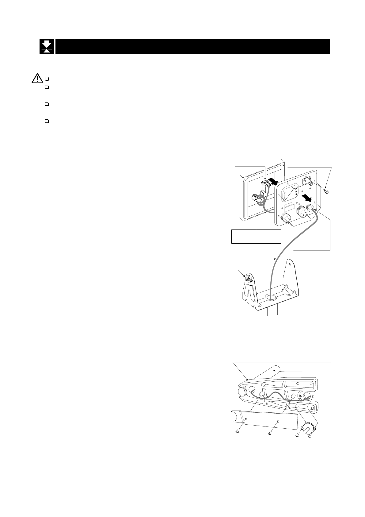
Step 8 Removing the bracket from the base unit,
Allen wrench
requires the following allen wrench.
HV-15KV-WP,
HV-60KV-WP,
HW-10KV-WP,
HW-60KV-WP
HV-200KV-WP,
HW-100KV-WP,
HW-200KV-WP
5mm Allen wrench 6mm Allen wrench
Step 9 Wind the cable through the ferrite core two
times. Affix the cable to the rear cover using the
cable clamp.
Step 10 Connect the cable to the connector. Close the
rear cover.
Step 11 Confirm the accuracy of the scale.
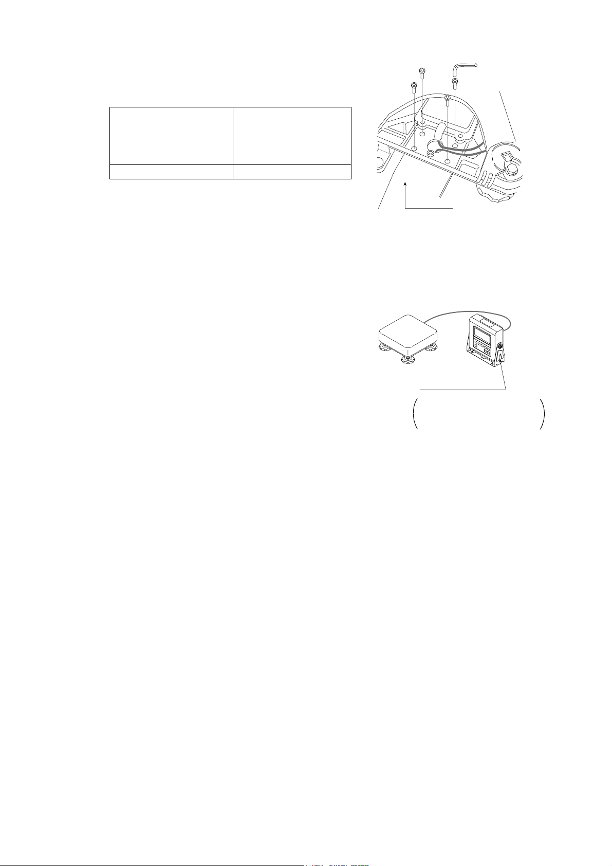
* An example of a scale installation after the pole
has been removed and includes the optional
Allen head screw
Bracket
Indicator holder
To be purchased
separately as an option.
Indicator holder
Option…AX:043005266 (Indicator holder)
5. 1. Removing the ploe
Page 10 HV-WP/HW-WP Series
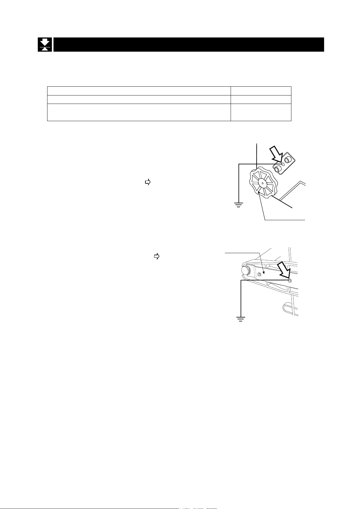
5.2. Grounding the Scale
When using where there may be static electricity, ground the scale.
The grounding procedure depends on the scale model. Refer to the table below.
These procedures are only for grounding part of the scale.
Models Refer to
HV-15KV-WP, HW-10KV-WP
HV-60KV-WP, HV-200KV-WP
HW-60KV-WP, HW-100KV-WP, HW-200KV-WP
Procedure A
(HV-15KV-WP, HW-10KV-WP)
Secure the grounding cable using a M4 screw in the
screw hole between the two hexagon bolts on the
base unit bottom side. (Part of “ ”)
Procedure B
(HV-60KV-WP, HV-200KV-WP, HW-60KV-WP, HW-100KV-WP, HW-200KV-WP)
Secure the grounding cable using the screw that
secures the under cover. (Part of “ ”)
Procedure A
Procedure B
Levering feet
Under cover
Base unit
bottom side
Base unit
bottom side
HV-WP/HW-WP Series Page 11
5. 2. Grounding the Balance
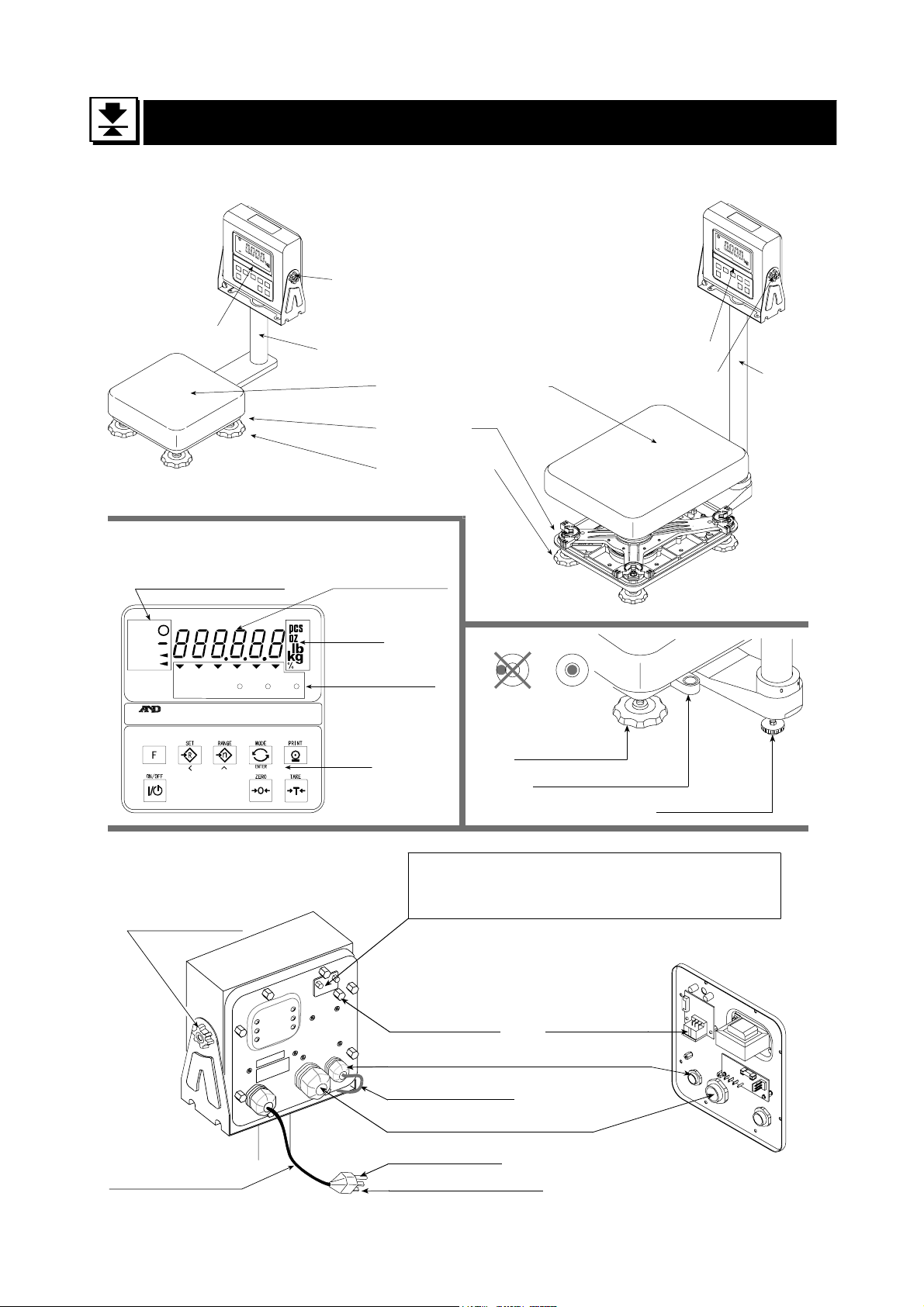
6. Names
Models
HV-15KV-WP
HW-10KV-WP
Display Unit
Display
Knob for
angle adjustment
Pole
Pan (Weighing Pan)
Base Unit
Leveling Foot
Models
HV-60KV-WP
HV-200KV-WP
HW-60KV-WP
HW-100KV-WP
HW-200KV-WP
Display Unit
Knob for
angle adjustment
Pole
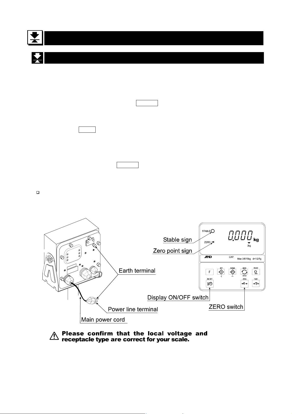
Weighing condition
STABLE
NET
ZERO
PT READY M+ 15kg 6kg 3kg
HI OK LO
CAP.
Max 3/6/15kg d=1/2/5g
Weighing data
Keys
Rear of Indicator Unit
Knob for angle
adjustment
Units
Indicator of
function
Earth terminal
OKNG
Leveling Foot
Bubble Spirit Level
Leveling Foot
CAL switch is in a depth of 5cm.
Calibrating the scale to weigh correctly.
Use the proper OIML class calibration mass.
Inside of rear panel
RS-232C
DIN connector
Cable clamp for load cell cable
Load cell cable
Cable clamp for option
Earth terminal
Main power cord
Power line terminal
Please Confirm that the local
voltage and receptacle type are
correct for your scale.
6.Names
Page 12 HV-WP/HW-WP Series
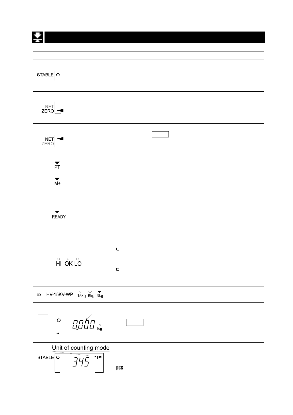
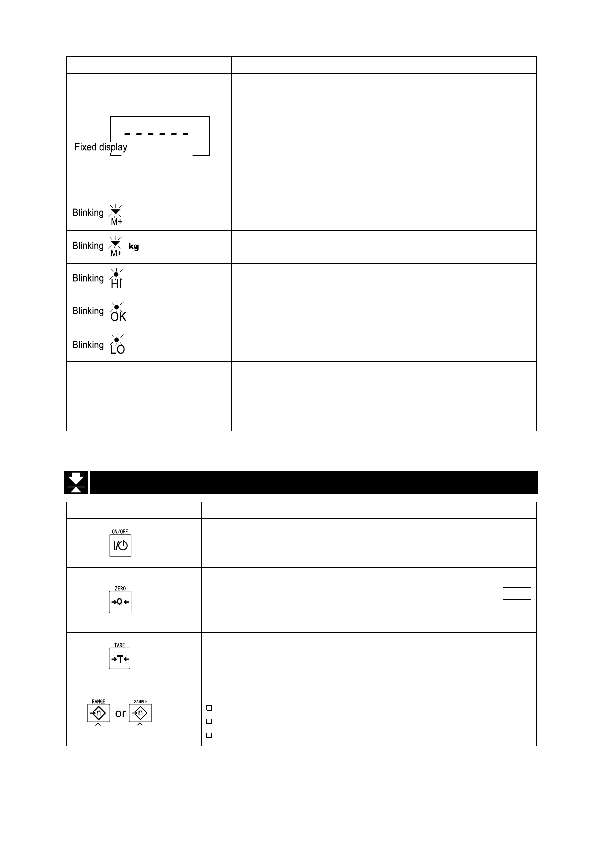
6.1. Display and Symbols
Display and Symbols Meaning
Weighed mass value
STABLE
ZERO
unit
Stability mark.
When the current weighing value is stable, this mark is
displayed, indicating a condition where the value is
readable.
Zero point mark.
With nothing on the weighing pan and pressing the
ZERO switch, this mark is displayed. The zero point is a
fundamental starting point to weigh anything.
Net mark.
Pressing the TARE switch, this mark is displayed with
net display.
Used to indicate that the mass of the container placed
on the pan has been subtracted from the gross value.
Preset tare mark.
Storing a tare with digital input, this mark blinks.
Accumulation mark.
Using the accumulation function, this mark is displayed.
Ready mark for the full/dribble batch function. The
meaning of the mark is as follows:
ON The weighing value is within the zero-band.
OFF The full/dribble batch process is above the
zero-band.
Blinking The start or end of the full/dribble batch
process in not within the zero-band.
The comparator indicator.
Using the comparator function and comparing a
weighing value with the upper and lower limits, the
result is indicated.
Using the full/dribble batch function, the full flow
gate indicator is OK, the dribble flow gate indicator
is HI and the zero band indicator is LO.
The weighing range indicator for the HV-WP series.
The current range is indicated.
Example. Display of zero (zero point).
With nothing on the weighing pan and pressing
the ZERO switch, this mark is displayed.
The zero point mark is displayed.
The stability mark is displayed.
Example. Display of the counting mode.
This mode uses the registered unit mass, and counts
the amount of articles on the weighing pan. The unit is
.
A
A
A
A
A
A
A
A
A
A
A
A
A
A
A
A
A
A
A
A
A
A
A
A
A
A
A
A
A
A
A
A
A
A
A
A
A
A
A
HV-WP/HW-WP Series Page 13
6.1. Display and Symbols
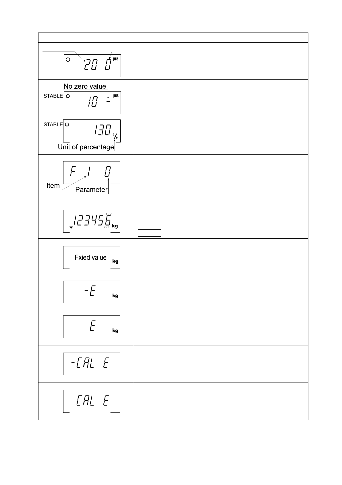
Display and Symbols Meaning
STABLE
The "digit" is a unit of display, and is equivalent to the minimum measurable mass.
The " nearly-zero " is within ±5 digits from zero point in the unit of kg.
Zero value20 pieces
Example. Storing the unit mass of the counting mode.
The unit mass is stored, using 20 pieces of samples.
The zero value means that no articles are on the pan.
Example. Storing the unit mass of the counting mode.
The unit mass is stored, using 10 pieces of samples.
The sign "-" means "weighing value is not zero".
Example. Percentage mode.
This mode uses the registered 100% mass, and converts
the weighing value to a percentage. The unit is % .
Example. Display of the function table.
This function table sets parameters of items.
ENTER switch Selecting an item.
∧ and < switches Selecting the parameter of an item.
ENTER switch Storing new parameters.
Example. Preset tare. Entering tare with digital input.
< switch Selecting a figure.
PT
∧ switch Selecting a number.
ENTER switch Storing a new tare.
Example. Hold display
The hold display is set using f12 of the function table.
When the value is "nearly-zero" or changes more than
25% +30 digits, the hold is canceled.
Weighing error.
Check the base unit and weighing pan.
Over load display.
Remove the mass from the weighing pan.
Calibration error.
The calibration mass is too light.
Check the base unit and weighing pan.
Calibration error.
The calibration mass is too heavy.
Check the base unit and weighing pan.
A
A
A
A
A
A
A
A
A
A
A
A
A
A
A
A
A
A
A
A
A
A
A
A
A
A
A
A
A
A
A
A
A
A
A
A
A
A
6.1. Display and Symbols
Page 14 HV-WP/HW-WP Series
Display and Symbols Meaning
CAP. MAX. 3/6/15kg d=1/2/5g
A
Does not display zero when the scale is turned on.
Remove anything that is on the weighing pan.
Perform zero point calibration.
Or
The weight value is unstable due to drift or vibration
when the scale is turned on.
A breeze or vibration may be affecting the
measurement.
Check around the weighing pan.
Accumulated data count.
Total mass value of the accumulated data.
Comparator function, display is an upper limit.
Full/dribble batch function, the display is a final value.
Full/dribble batch function, the display is a preliminary
value.
Comparator function, display is a lower limit.
Full/dribble batch function, the display is the zero band.
Description of the weighing unit, weighing range and
measurable minimum mass.
Example: Displays the weight value by 5 g up to 15 kg.
Displays the weight value by 2 g up to 6 kg.
Displays the weight value by 1 g up to 3 kg.
A
A
A
A
A
A
A
A
A
A
A
A
A
A
A
6.2. Switches
Display and Symbols Meaning
Display ON/ OFF switch.
Note Standby status when power is connected.
ZERO switch.
When there is nothing on the weighing pan and the ZERO
switch is pressed, the scale displays the mass value of zero
and the zero point mark. Net is canceled, if it is displayed.
TARE switch.
Canceling the mass of a receptacle, case, bag, etc. which is
put on the weighing pan, and does not weigh its mass.
RANGE switch, SAMPLE switch.
Changing weighing range for HV-WP series.(Refer to f2 )
Storing the unit mass, it is used to select a sample number.
In the function table, it is used to select a parameter.
A
A
A
A
A
A
A
A
A
A
A
A
A
A
A
HV-WP/HW-WP Series Page 15
6.2. Switches
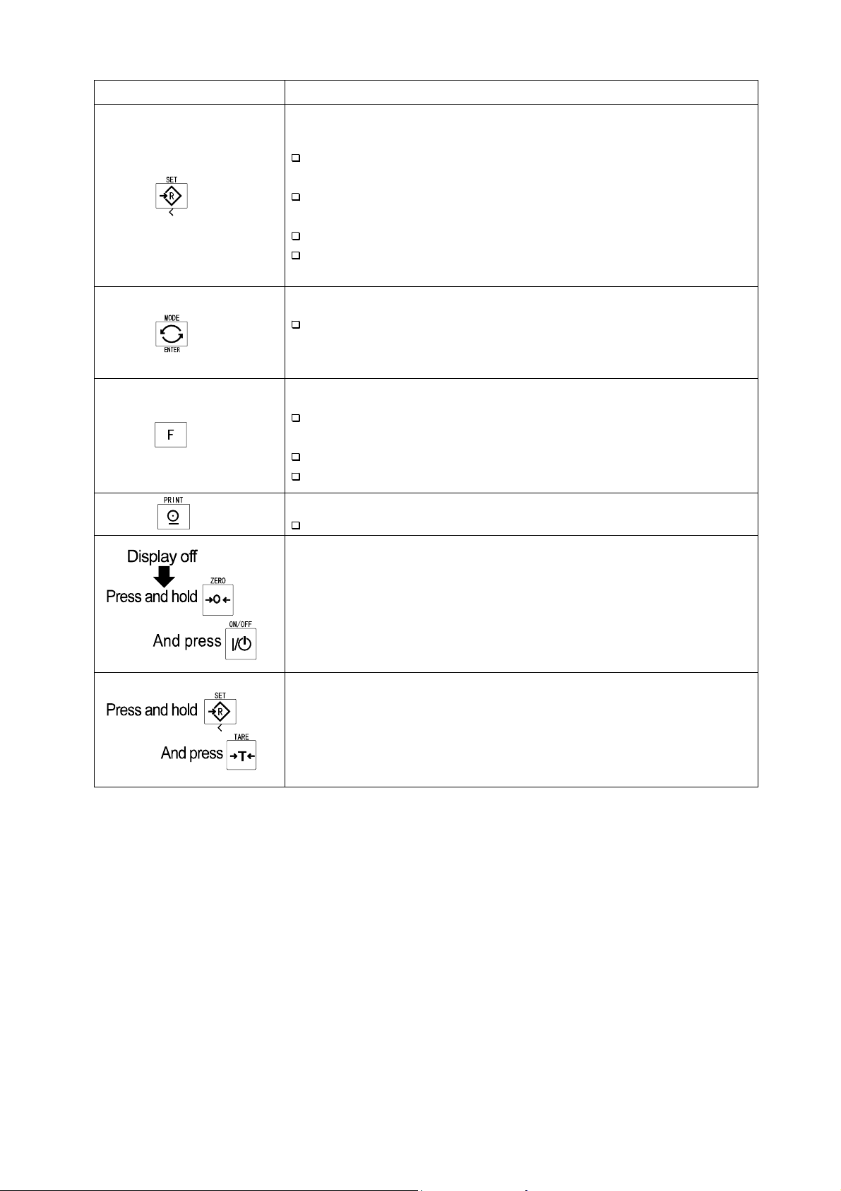
Display and Symbols Meaning
SET switch.
Turns the comparator on/off. (Refer to f6 )
Counting mode, it is used to enter the mode to store the
unit mass.
Percentage mode, it is used to enter the mode to store the
100% mass.
The full/dribble batch function, it is used as a start switch.
For the preset tare and selecting a calibration mass, it is
used to select a figure.
MODE switch.
Changing the current unit.
While setting modes, this switch is used for " storing a
parameter and proceeding to the next step".
F switch.
Full/dribble batch function, it is used to finish the process.
(Refer to f10 )
Hold switch. (Refer to f12 )
Comparator function, selects polarity (+,-).
PRINT switch.
Used to print or output data. (Refer to f5 )
Used to enter the function table.
Used to enter the mode to set a preset tare.
A
A
A
A
A
A
A
A
A
A
A
A
A
A
A
A
A
A
A
A
A
A
A
A
A
A
A
A
A
6.2. Switches
Page 16 HV-WP/HW-WP Series
7. Basic Operation
7.1. Turning the Scale on/off and Weighing
Step 1 Ground the scale using the earth terminal.
Step 2 Place nothing on the weighing pan.
Step 3 Confirm that local voltage and receptacle type adapt to your scale.
Step 4 The scale turns on/off using the ON/OFF switch alternately.
Step 5 Check the accuracy of weighing. If you calibrate the scale, perform it after turning
the scale on for 30 minutes (warming up).
Step 6 Press the ZERO switch to display zero. (with nothing on the weighing pan.)
Step 7 Place an item on the weighing pan gently.
Step 8 You can read the mass value after the stability mark is displayed.
Step 9 Remove the item from the weighing pan.
Step 10 Turn the scale using the ON/OFF switch off.
Memo
With the power cord connected, the scale consumes only the power for standby
status after turning off the scale. To shut down the power completely, disconnect the
power cord.
HV-WP/HW-WP Series Page 17
7. Basic Operation
7.2. Tare (And Net Display)
"Tare" is used to cancel the mass of a container, receptacle, case, bag, etc. which is
put on the weighing pan to contain the item to be weighed.
Caution
Using a tare value reduces the weighing range.
The current tare value is reset by pressing the ZERO switch or turning the
scale off. (Reset value is zero.)
The preset tare value must be within the minimum weighing range for the HV-WP series.
7.2.1. The Way of Tare Input by Weighing
Step 1 Put the container item on the weighing pan.
Step 2 Wait for the stability mark to be displayed. Press the TARE switch. The display
becomes zero and the net mark is displayed.
Step 3 It is now possible to put something into the container. Wait for the stability mark to
be displayed and to read its net display.
Step 4 Remove all things on the weighing pan.
7.2.2. The Way of Digital Input (Preset Tare)
Step 1 Press and hold the SET switch and press the TARE switch.
Then the blank or stored tare value is displayed. A blank display means that the
tare value is zero (reset value), and blinks.
Step 2 Set the preset tare value by using the following switches.
∧ switch Selecting the number of the figure.
< switch Selecting a figure.
Step 3 Press the ENTER switch to store the new preset tare value.
Then the scale displays a net value with the tare value subtracted from the gross
weighing value.
Step 4 It is then possible to put something into the container. Wait for the stability mark to
be displayed and to read its net.
Step 5 Remove all things from the weighing pan.
7. Basic Operation
Page 18 HV-WP/HW-WP Series
7. Basic Operation
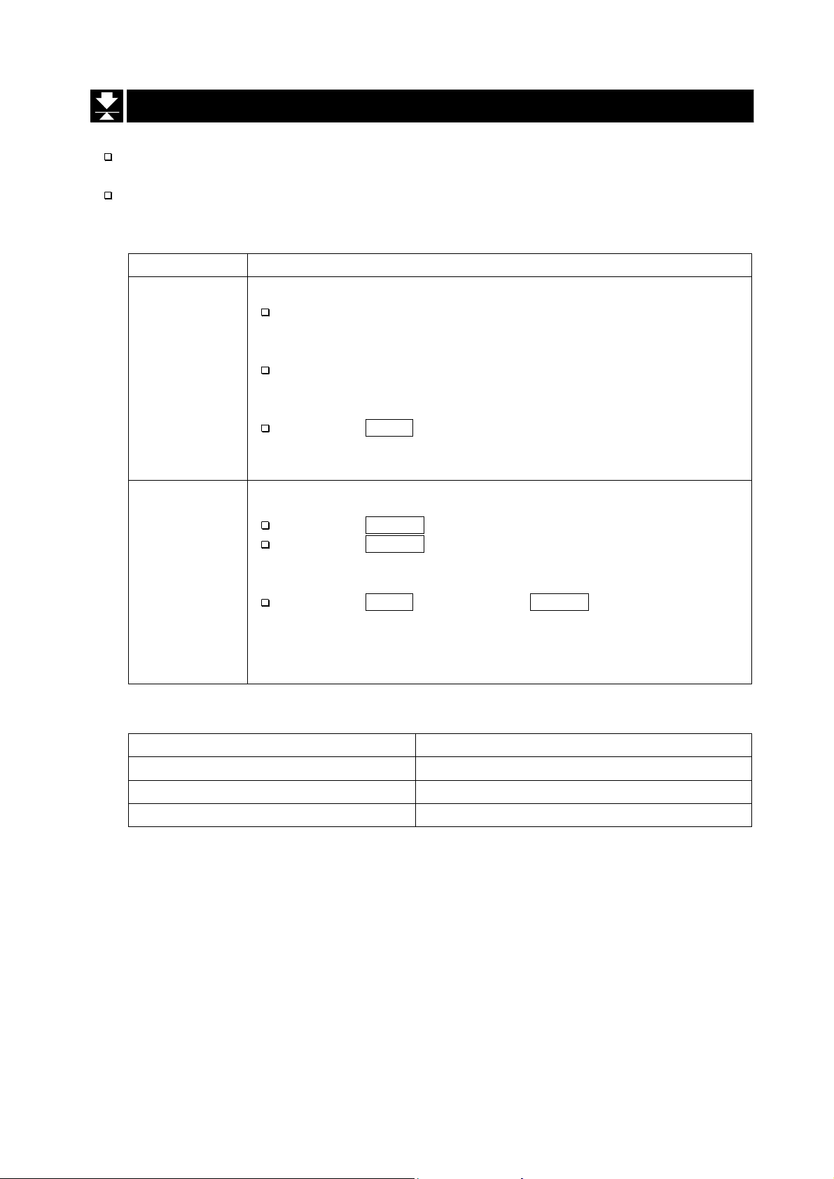
7.3. Weighing Range for the HV-WP Series
This is the function to select a weighing range for the HV-WP series.
The mass value is displayed within a selected range.
Select automatic range (f2 0) or manual range (f2 1) in the function table.
Operation and Performance
Function table Meaning and purpose
Automatic range
The weighing range changes automatically, if the weighing
value proceeds from narrow range to wide range when
placing articles on the weighing pan.
f2 0
f2 1
When there is nothing on the weighing pan and the zero point
mark is displayed, it changes to the minimum range
automatically.
Press the ZERO switch to change to the minimum range,
when there is nothing on the weighing pan and the zero point
mark is not displayed due to net display or zero error.
Manual range
Press the RANGE switch to expand the range.
Press the RANGE switch to change to the minimum range,
when there is nothing on the weighing pan and the zero point
mark is displayed.
Press the ZERO switch and the RANGE switch to change to
the minimum range, when there is nothing on the weighing
pan and the zero point mark is not displayed due to net display
or zero error.
A
A
A
A
A
A
A
A
A
A
A
A
A
A
A
A
A
A
A
Weighing Range
Models Weighing Range
HV-15KV-WP 3kg, 6kg, 15kg
HV-60KV-WP 15kg, 30kg, 60kg
HV-200KV-WP 60kg, 150kg, 220kg
HV-WP/HW-WP Series Page 19
7. Basic Operation
A
A
A
A
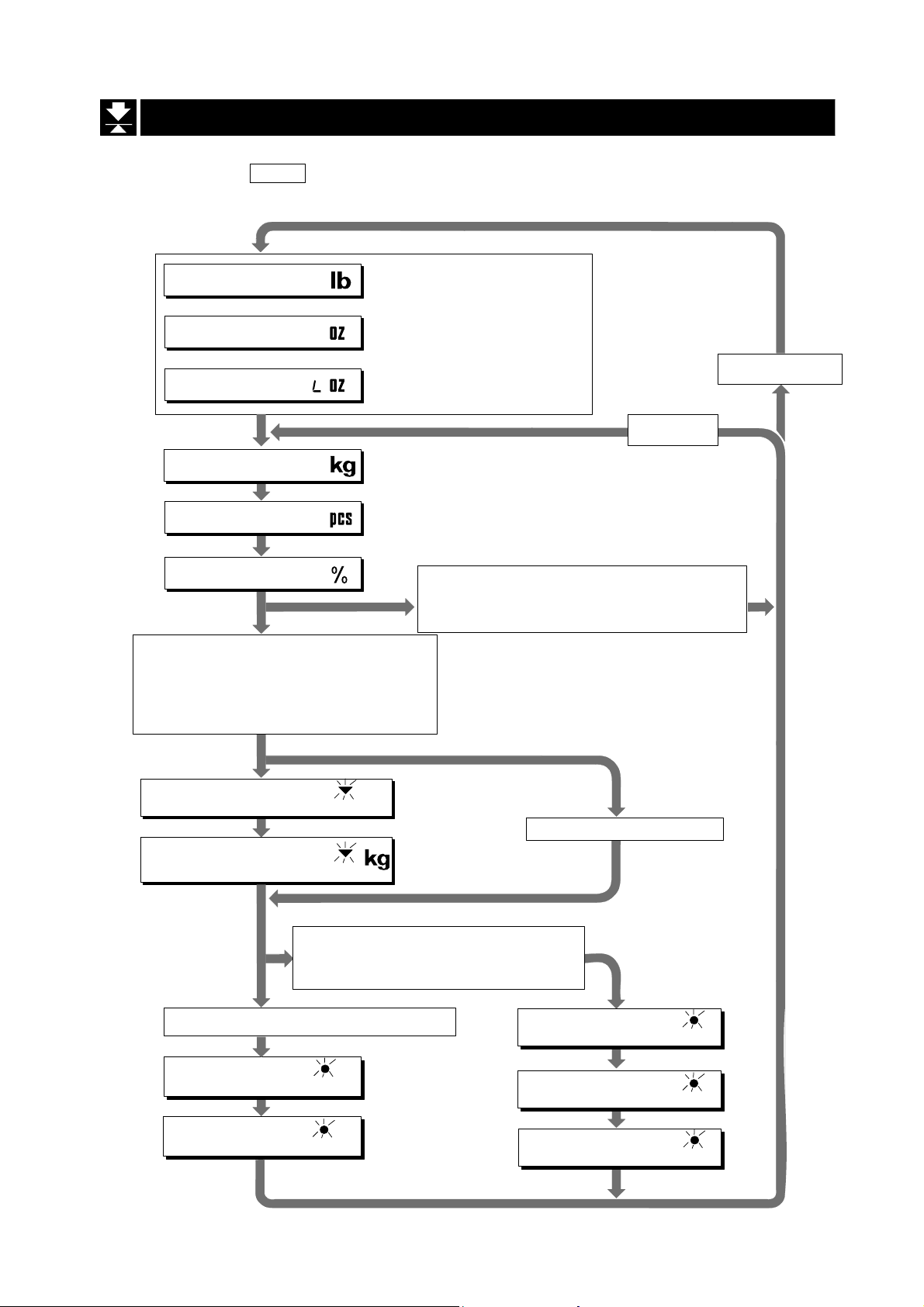
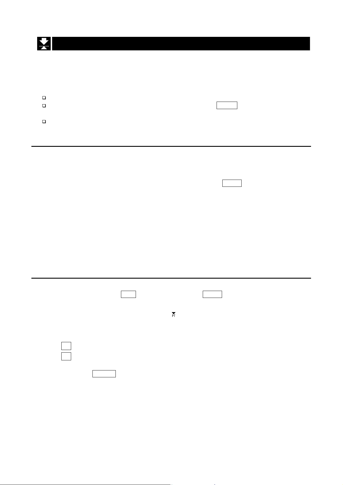
7.4. Mode Switch (Changing Unit and Mode)
Pressing the MODE switch, the display changes as follows. Refer to function table f3
for units. Usable units are according to the factory settings.
Pound
Ounce
Pound-Ounce
Metric kg
Counting Mode
Percentage Mode
Either function is active.
Comparator (f6 0 ~ f6 7)
Simple Batch Function (f6 8)
Full/Dribble Batch Function (f6 9)
Accumulation Function (
Accumulation Count
Accumulation Value
Active Simple Batch Function or
Active Full/Dribble Batch Function
If the law in your area
premits, you may use all
of the units. Also, some
dealers may initially turn
off units which are not
regularly used.
Inactive Comparator (f6)
Inactive Accumulation Function (
)
f8 1
M+
M+
(
f6 8, f6 9
)
Metric unit
and
f8 0
No Accumulation Data
Non metric units
)
Active Comparator (f6 0 ~ f6 7)
Final value
HI
Comparator
Upper limit
HI
Preliminary value
OK
Comparator
Lower limit
Page 20 HV-WP/HW-WP Series
7. Basic Operation
LO
Zero band
LO
Explanation
The status of "Inactive comparator (f6)" is that comparator function (f6 0, f6 2, f6 4, f6 6)
is selected and the comparator is not used. The "active" or "Inactive" (ON/OFF) for the
comparator can be selected by pressing the SET switch alternately.
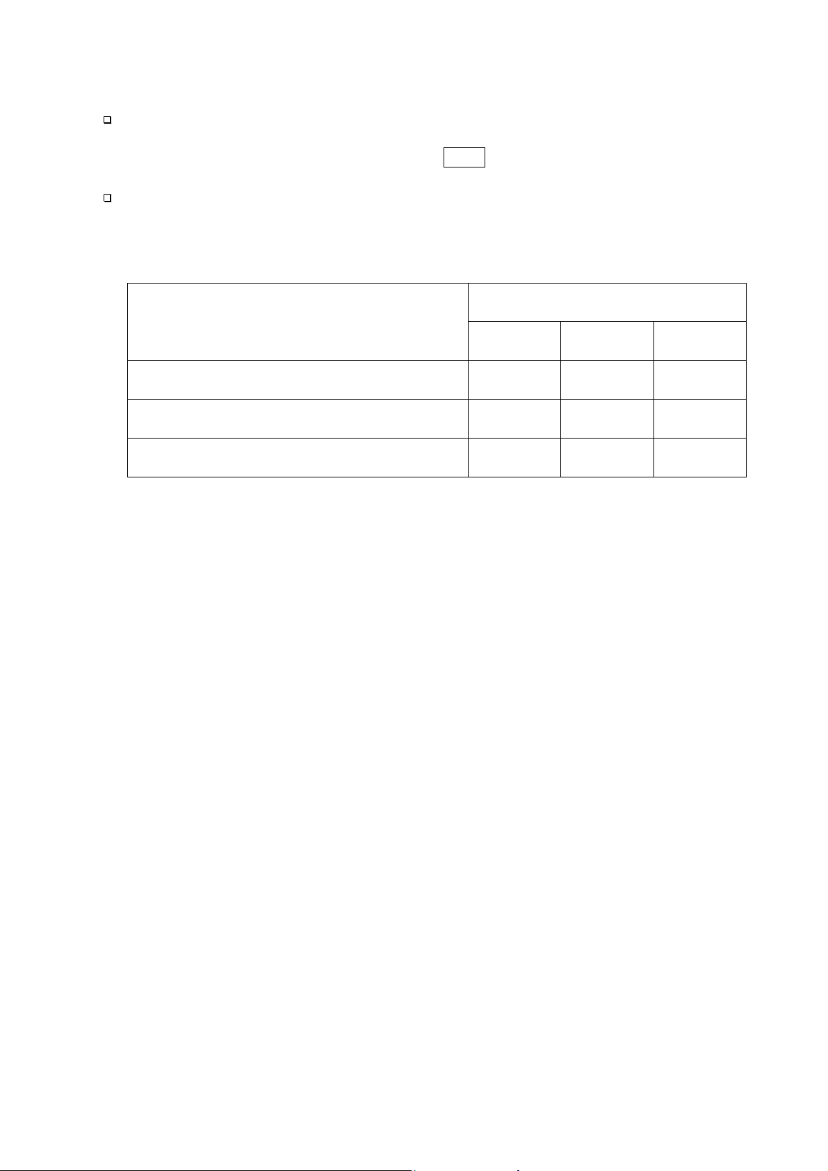
The following parameters are stored in the same memory. Therefore, the functions
can not be used at the same time. If you use each function, it will be necessary to
select the function from the function table, to set the parameters of HI,OK and LO, to
weigh it using the function.
Indicator and Output
HI OK LO
Upper/Lower Comparator Function (f6 0 ~ 7)
Simple Batch Function (f6 8)
Full/ Dribble Batch Function (f6 9)
Upper limit Lower limit
Final value
Final value
Preliminary
value
Preliminary
value
Zero band
Zero band
HV-WP/HW-WP Series Page 21
7. Basic Operation
 Loading...