


SV-10
SV-100
Vibro Viscometer
INSTRUCTION
 MANUAL
1WMPD4000646E
© 2008 A&D Company Ltd. All rights reserved.
No part of this publication may be reproduced, transmitted, transcribed, or translated into any language in any form by any means without the written permission of A&D Company Ltd.
The contents of this manual and the specifications of the instrument covered by this manual are subject to change for improvement without notice.

CONTENTS |
|
1. INTRODUCTION ............................................................................................................................. |
3 |
1-1 Compliance......................................................................................................................................... |
3 |
1-2 Features ............................................................................................................................................. |
5 |
2. UNPACKING THE VISCOMETER .................................................................................................. |
6 |
2-1 Unpacking........................................................................................................................................... |
6 |
2-2 Installing the Viscometer .................................................................................................................... |
7 |
3. DISPLAY AND KEYS ...................................................................................................................... |
8 |
3-1 Display................................................................................................................................................ |
8 |
3-2 Keys.................................................................................................................................................... |
9 |
3-3 Displaying the Viscosity Values ........................................................................................................ |
10 |
3-3-1 SV-10......................................................................................................................................... |
10 |
3-3-2 SV-100........................................................................................................................................ |
11 |
4. PRECAUTIONS ............................................................................................................................ |
12 |
4-1 General Precautions......................................................................................................................... |
12 |
4-2 During Use........................................................................................................................................ |
13 |
4-3 After Use........................................................................................................................................... |
14 |
4-4 Measuring the Absolute Value of Viscosity....................................................................................... |
15 |
4-4-1 At Measurement ........................................................................................................................ |
15 |
4-4-2 At Calibration ............................................................................................................................. |
16 |
5. MEASUREMENT .......................................................................................................................... |
17 |
5-1 Preparing the Sample....................................................................................................................... |
17 |
5-2 Basic Measurement Procedure ........................................................................................................ |
19 |
5-3 Changing Units ................................................................................................................................. |
20 |
6. VISCOSITY CALIBRATION .......................................................................................................... |
21 |
6-1 Notes on Viscosity Calibration.......................................................................................................... |
21 |
6-2 Calibration Procedure....................................................................................................................... |
22 |
6-2-1 One-point Calibration................................................................................................................. |
23 |
6-2-2 Two-point Calibration................................................................................................................. |
24 |
6-2-3 Simplified Calibration Using Purified Water (SV-10 only).......................................................... |
26 |
7. FUNCTION SETTING.................................................................................................................... |
28 |
7-1 Operation.......................................................................................................................................... |
28 |
7-2 Details of the Function Items............................................................................................................ |
30 |
7-3 Description of Items.......................................................................................................................... |
31 |
7-4 Data Output Format Examples......................................................................................................... |
40 |
7-4-1 A&D Standard Format................................................................................................................ |
40 |
7-4-2 D.P. Format................................................................................................................................ |
42 |
7-4-3 CSV Format............................................................................................................................... |
43 |
7-4-4 RsVisco Format ......................................................................................................................... |
47 |
1
8. CONNECTION TO A PERSONAL COMPUTER........................................................................... |
49 |
9. CONNECTION TO A PRINTER .................................................................................................... |
48 |
10. RS-232C SERIAL INTERFACE .................................................................................................. |
51 |
11. COMMAND LIST......................................................................................................................... |
52 |
12. TROUBLESHOOTING................................................................................................................ |
53 |
13. ERROR DISPLAY ....................................................................................................................... |
57 |
14. SPECIFICATIONS....................................................................................................................... |
58 |
15. OPTIONAL ACCESSORIES ....................................................................................................... |
60 |
16. EXTERNAL DIMENSIONS ......................................................................................................... |
64 |
Whole View ......................................................................................................................................... |
64 |
Detailed View of the Sensor Unit ........................................................................................................ |
64 |
2

1. INTRODUCTION
This manual describes how the SV series viscometer works and how to get the most out of it in terms of performance.
Read this manual thoroughly before using the viscometer and keep it at hand for future reference.
1-1 Compliance
Compliance with FCC Rules
Please note that this device generates, uses and can radiate radio frequency energy. This device has been tested and has been found to comply with the limits of a Class A computing device pursuant to Subpart J of Part 15 of FCC rules. These rules are designed to provide reasonable protection against interference when this device is operated in a commercial environment. If this unit is operated in a residential area, it may cause some interference and under these circumstances the user would be required to take, at his own expense, whatever measures are necessary to eliminate the interference.
(FCC = Federal Communications Commission in the U.S.A.)
Compliance with Council Directives
This device features radio interference suppression and safety regulation in compliance with the following Council Directives
Council directive 89/336/EEC |
EN61326 |
EMC directive |
Council directive 73/23/EEC |
EN60950 |
Safety of Information Technology Equipment |
EN61326 Emission and Immunity.
Note
The CE mark is an official mandatory European marking.
Please note that any electronic product must comply with local laws and regulations when sold or used anywhere outside Europe.
3
4

1-2 Features
High accuracy
The Sine-wave Vibro Viscometer achieves a high measurement accuracy of 1%*1 (repeatability) over the full range.
*1 Refer to "14. SPECIFICATIONS" on page 58.
Wide range continuous measurement
Continuous measurement over the whole measuring range is possible, without replacing the viscosity detection sensor plates.
Standard temperature sensor
The temperature sensor to measure the sample temperature is installed as standard. The temperature sensor is located between the two sensor plates. So, the accurate detection of the relation between temperature and viscosity is possible.
Accurate measurement
Due to the low heat capacity of the viscosity detection unit (sensor plates and temperature sensor), the time required for temperature equilibrium is short. Thus, the sample viscosity can be measured accurately in a short time.
Long continuous measurement time
The sensor plates, with a low frequency of 30 Hz and an amplitude of less than 1 mm, apply very little load to the sample. So, the viscometer can continuously obtain stable viscosity values without causing a temperature rise or damaging the sample.
Measurement of a non-Newtonian fluid/foaming sample
The thin sensor plates allow little deformation of the sample texture. Thus, non-Newtonian fluid can be measured in a stable way. And, foaming samples can be measured without breaking minute foam particles and with less influence scattering large foam particles.
When measuring tap water, bubbles may accumulate on the sensor plates, increasing the viscosity.
Measurement of a flowing sample
The two sensor plates oscillate in the opposite direction. So, even when a sample is in motion, errors are eliminated. This allows measurement of a sample while being stirred. The viscometer can be used for a flowing product line, which enables field management with identical data used at the laboratories.
Calibration
The viscometer can be calibrated using a standard viscosity fluid or a sample of a known viscosity. Calibration allows the viscometer to maintain the accuracy constantly.
By calibrating an actual sample, using the viscosity value obtained by another type of viscometer as a correction value, the measurement data obtained by the SV series viscometer can be combined into those obtained by the other type of viscometer.
Simplified calibration when measuring the viscosity near 1 mPa s, (SV-10 only)
Simplified calibration using purified water is a one-key operation. The SV-10 has a built-in function to measure the temperature of the purified water using the temperature sensor and calculates the viscosity value of the purified water at that temperature.
At this time, be careful not to influence the viscosity value by generating bubbles.
Standard windows communication tools WinCT-Viscosity
Windows communication tools WinCT-Viscosity (CD-ROM) is provided as standard. The CD-ROM contains the graphing program RsVisco, which imports the data to a personal computer and displays the results as a graph in real time. With RsVisco, changes in viscosity over time and temperature dependency of viscosity can be observed easily and the obtained data can be saved in files.
5

2. UNPACKING THE VISCOMETER
2-1 Unpacking
The viscometer is a precision instrument. Unpack the viscometer carefully. Keep the packing material to be used for transporting the viscometer in the future.
Accessories
Note
Please confirm that the AC adapter type is correct for your local voltage and receptacle type.
6

2-2 Installing the Viscometer
Install the viscometer as follows:
1Connect the display unit to the main unit using the connection cable.
2Insert the AC adapter plug into the AC adapter jack located on the rear side of the display unit. Insert the other end of the AC adapter plug into an electrical outlet.
Note:
•Confirm that the adapter type is correct for the local voltage and power receptacle type.
•The main unit and the display unit have been adjusted in pairs. For accurate viscosity measurement, before use, confirm that the main unit and the display unit have the same serial number.
7
3. DISPLAY AND KEYS
3-1 Display
|
|
|
|
|
|
|
|
|
|
|
|
|
|
|
|
|
|
|
|
|
|
|
|
|
|
|
|
|
|
|
|
|
|
|
|
|
|
|
|
|
|
|
|
|
|
|
|
|
|
|
|
|
|
|
|
|
|
|
|
|
|
|
|
|
|
|
|
|
|
|
|
|
|
|
|
|
|
|
|
|
|
|
|
|
|
|
|
|
|
|
|
|
|
|
|
|
|
|
|
|
|
|
|
|
|
|
|
|
|
|
|
|
|
|
|
|
|
|
|
|
|
|
|
|
|
|
|
|
|
|
|
|
|
|
|
|
|
|
|
|
|
|
|
|
|
|
|
|
|
|
|
|
|
|
|
|
|
|
|
|
|
|
|
|
|
|
|
|
|
|
|
|
|
|
|
|
|
|
|
|
|
|
|
|
|
|
|
|
|
|
|
|
|
|
|
|
|
|
|
|
|
|
|
|
|
|
|
|
|
|
|
|
|
|
|
|
|
|
|
|
|
|
|
|
|
|
|
|
|
|
|
|
|
|
|
|
|
|
|
|
|
|
|
|
|
|
|
|
|
|
|
|
|
|
|
|
|
|
|
|
|
|
|
|
|
|
|
|
|
|
|
|
|
|
|
|
|
|
|
|
|
|
|
|
|
|
|
|
|
|
|
|
|
|
|
|
|
|
|
|
|
|
|
|
|
|
|
|
|
|
|
|
|
|
|
|
|
|
|
|
|
|
|
|
|
|
|
|
|
|
|
|
|
|
|
|
|
|
|
|
|
|
|
|
|
|
|
|
|
|
|
|
|
|
|
|
|
|
|
|
|
|
|
|
|
|
|
|
|
|
|
|
|
|
|
|
|
|
|
|
|
|
|
|
|
|
|
|
|
|
|
|
|
|
|
|
|
|
|
|
|
|
|
|
|
|
|
|
|
|
|
|
|
|
|
|
|
|
|
|
|
|
|
|
|
|
|
|
|
|
|
|
|
|
|
|
|
|
|
|
|
|
|
|
|
|
|
|
|
|
|
|
|
|
|
|
|
|
|
|
|
|
|
|
|
|
|
|
|
|
|
|
|
|
|
|
|
|
|
|
|
|
|
|
|
|
|
|
|
|
|
|
|
|
|
|
|
|
|
|
|
|
|
|
|
|
|
|
|
|
|
|
|
|
|
|
|
|
|
|
|
|
|
|
|
|
|
|
|
|
|
|
|
|
|
|
|
|
|
|
|
|
|
|
|
|
|
|
|
|
|
|
|
|
|
|
|
|
|
|
|
|
|
|
|
|
|
|
|
|
|
|
|
|
|
|
|
|
|
|
|
|
|
|
|
|
|
|
|
|
|
|
|
|
|
|
|
|
|
|
|
|
|
|
|
|
|
|
|
|
|
|
|
|
|
|
|
|
|
|
|
|
|
|
|
|
|
|
|
|
|
|
|
|
|
|
|
|
|
|
|
|
|
|
|
|
|
|
|
|
|
|
|
|
|
|
|
|
|
|
|
|
|
|
|
|
|
|
|
|
|
|
|
|
|
|
|
|
|
|
|
|
|
|
|
|
|
|
|
|
|
|
|
|
|
|
|
|
|
|
|
|
|
|
|
|
|
|
|
|
|
|
|
|
|
|
|
|
|
|
|
|
|
|
|
|
|
|
|
|
|
|
|
|
|
|
|
|
|
|
|
|
|
|
|
|
|
|
|
|
|
|
|
|
|
|
|
|
|
|
|
|
|
|
|
|
|
|
|
|
|
|
|
|
|
|
|
|
|
|
|
|
|
|
|
|
|
|
|
|
|
|
|
|
|
|
|
|
|
|
|
|
|
|
|
|
|
|
|
|
|
|
|
|
|
|
|
|
|
|
|
|
|
|
|
|
|
|
|
|
|
|
|
|
|
|
|
|
|
|
|
|
|
|
|
|
|
|
|
|
|
|
|
|
|
|
|
|
|
|
|
|
|
|
|
|
|
|
|
|
|
|
|
|
|
|
|
|
|
|
|
|
|
|
|
|
|
|
|
|
|
|
|
|
|
|
|
|
|
|
|
|
|
|
|
|
|
|
|
|
|
|
|
|
|
|
|
|
|
|
|
|
|
|
|
|
|
|
|
|
|
|
|
|
|
|
|
|
|
|
|
|
|
|
|
|
|
|
|
|
Name |
|
|
|
|
|
|
|
|
|
|
|
|
Description |
|
|
|
|
|
|
|||||||||||||||||
|
|
|
|
|
|
|
|
Standby mode |
|
|
|
|
Displays [- - - - -]. |
||||||||||||||||||||||||
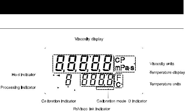
Viscosity display |
|
Measurement mode |
|
|
|
|
Displays the viscosity value in real |
||||||||||||||||||||||||||||||
|
|
|
|
|
time. |
|
|
|
|
|
|
||||||||||||||||||||||||||
|
|
|
|
|
|
|
|
|
|
|
|
|
|
|
|
|
|
|
|
|
|||||||||||||||||
|
|
|
|
|
|
|
|
Data hold mode |
|
|
|
|
Freezes the display of the viscosity |
||||||||||||||||||||||||
|
|
|
|
|
|
|
|
|
|
|
|
value. |
|
|
|
|
|
|
|||||||||||||||||||
|
|
|
|
|
|
|
|
|
|
|
|
|
|
|
|
|
|
|
|
|
|
|
|
|
|
|
|
||||||||||
Viscosity units |
|
Displays the unit of viscosity. |
|
|
|
|
|
|
|
|
|
|
|
|
|
|
|
|
|||||||||||||||||||
|
|
|
|
|
|
|
|
Standby mode |
|
|
|
|
Displays the temperature value in |
||||||||||||||||||||||||
Temperature display |
|
Measurement mode |
|
|
|
|
real time. |
|
|
|
|
|
|
||||||||||||||||||||||||
|
Data hold mode |
|
|
|
|
Freezes the display of the |
|||||||||||||||||||||||||||||||
|
|
|
|
|
|
|
|
|
|
|
|
||||||||||||||||||||||||||
|
|
|
|
|
|
|
|
|
|
|
|
temperature value. |
|||||||||||||||||||||||||
|
|
|
|
|
|
|
|
|
|
|
|
|
|
|
|
|
|
|
|
|
|
||||||||||||||||
Temperature units |
|
Displays the unit of temperature. |
|
|
|
|
|
|
|||||||||||||||||||||||||||||
Processing indicator |
|
Blinks while the measurement is being performed. (While the |
|||||||||||||||||||||||||||||||||||
|
sensor plates are in vibrating motion) |
|
|
|
|
|
|
||||||||||||||||||||||||||||||
|
|
|
|
|
|
|
|
|
|
|
|
|
|
||||||||||||||||||||||||
Hold indicator |
|
Illuminates while the viscometer is in the data hold mode. |
|||||||||||||||||||||||||||||||||||
RsVisco link indicator |
|
Illuminates while measurement is performed using RsVisco, the |
|||||||||||||||||||||||||||||||||||
|
graphing program contained in the WinCT-Viscosity (CD-ROM). |
||||||||||||||||||||||||||||||||||||
|
|
|
|
|
|
|
|
||||||||||||||||||||||||||||||
Calibration indicator |
|
Displays " C " in the calibration mode. |
|
|
|
|
|
|
|||||||||||||||||||||||||||||
|
|
|
|
|
|
|
|
At one-point calibration |
|
|
|
|
|
|
|
|
|
|
|
|
|
|
|
Blank display [ ] |
|||||||||||||
Calibration mode ID |
|
|
|
|
|
|
|
|
|
|
|
|
|
|
|
Inputting |
|
Displays [ - ]. |
|||||||||||||||||||
|
|
|
|
|
|
|
|
|
|
|
|
|
|
|
first point |
|
|||||||||||||||||||||
indicator |
|
At two-point calibration |
|
|
|
|
|
|
|
|
|
|
|||||||||||||||||||||||||
|
|
|
|
|
Inputting |
|
Displays [ - - ]. |
||||||||||||||||||||||||||||||
|
|
|
|
|
|
|
|
|
|
|
|
|
|
|
|
|
|
|
|
|
|
|
|||||||||||||||
|
|
|
|
|
|
|
|
|
|
|
|
|
|
|
|
|
|
|
|
|
|
second point |
|
||||||||||||||
|
|
|
|
|
|
|
|
|
|
|
|
|
|
|
|
|
|
|
|
|
|
|
|
|
|
|
|
||||||||||
8
3-2 Keys
|
|
Key |
|
|
|
|
|
|
Description |
|||||
|
|
|
|
|
|
|
Turns the power on and off. |
|||||||
|
ON:OFF |
|
||||||||||||
|
|
|
When the power is turned on, the viscometer enters the standby |
|||||||||||
|
|
Power |
|
|||||||||||
|
|
|
mode ( [- - - - -] is displayed.) |
|||||||||||
|
|
|
|
|
|
|
||||||||
|
|
|
|
|
|
Start a measurement. (The processing indicator blinks.) |
||||||||
|
|
START |
||||||||||||
|
|
Start |
|
|
Displays the viscosity and temperature values in real time during |
|||||||||
measurement |
|
measurement. |
||||||||||||
|
|
|
|
|
|
|
|
|
|
|
|
|||
|
|
|
|
|
|
|
Stops the measurement (The processing indicator is off) and freezes |
|||||||
|
|
STOP |
|
|
the display of the viscosity and temperature values at the time the |
|||||||||
|
|
Stop |
|
|
STOP |
key is pressed during measurement. |
||||||||
measurement |
|
When |
the |
STOP |
key is pressed again, the viscometer enters the |
|||||||||
|
|
|
|
|
|
|
standby mode. |
|
|
|
|
|||
|
|
|
|
|
|
|
Freezes temporarily the display of the measurement data (viscosity |
|||||||
|
|
|
|
|
|
|
and temperature) at the time the |
HOLD |
key is pressed during |
|||||
|
|
HOLD |
|
|
measurement. (The hold indicator |
is on.) |
||||||||
Data hold |
|
In the above condition, the measurement is continued. (The processing |
||||||||||||
|
|
|
|
|
|
|
indicator blinks.) |
|||||||
|
|
|
|
|
|
|
Pressing the |
HOLD |
key again releases the data hold mode. 1 |
|||||
|
|
|
|
|
|
|
Changes viscosity units. 1 |
|||||||
|
|
MODE |
|
|
|
|
||||||||
|
|
|
|
(By the function setting "fnc 1", the measurement elapsed time can |
||||||||||
Change units |
|
|||||||||||||
|
be displayed.) |
|||||||||||||
|
|
|
|
|
|
|
||||||||
|
|
|
|
|
|
|
|
|
|
|
|
|
||
|
|
|
Outputs the measurement data. |
|||||||||||
Output data |
|
|||||||||||||
|
|
|
|
|
|
|
|
|
||||||
1 While the measurement is being performed using the graphing program RsVisco, the data hold mode using the HOLD key and unit changes using the MODE key are not available. RsVisco is contained in the accessory Windows communication tools, WinCT-Viscosity.
While data are being output continuously (function setting "prt 2" or SIR command), the data hold mode using the HOLD key is not available.
9

3-3 Displaying the Viscosity Values
The viscosity values are displayed as below, depending on the unit selected and the viscosity range.
The correlation of the units are as follows: 1 mPa s = 0.001 Pa s = 1 cP =0.01 P
3-3-1 SV-10
Use the MODE key to switch between mPa s (Millipascal second) and Pa s (Pascal second), or between cP (Centipoise) and P (Poise).
The unit selected at the factory before shipment is mPa s.
When the viscosity unit is mPa s or Pa s:
Viscosity |
|
|
|
Unit selected |
|
|
|
|
|
measured |
|
mPa s |
|
|
|
Pa s |
|
||
mPa s |
Display |
Minimum |
Unit |
Remarks |
Display |
Minimum |
|
Unit |
Remarks |
|
|
display |
|
|
|
display |
|
|
|
|
0.30 |
|
|
|
0.0003 |
|
|
|
Digit |
|
|
|
|
|
|
|
|
|
|
|
|
|
|
|
|
|
indicating |
||
1 |
1.00 |
0.01 |
|
|
0.0010 |
0.0001 |
|
|
|
|
|
|
|
0.01 mPa s is |
|||||
|
|
|
|
|
|
|
|
|
|
|
|
|
|
|
|
|
not displayed |
||
|
9.99 |
|
|
|
0.0099 |
|
|
|
|
|
|
mPas |
|
|
|
|
|
||
10 |
10.0 |
0.1 |
|
0.0100 |
0.0001 |
|
|
|
|
|
|
|
|
|
|
Pas |
|
||
|
99.9 |
|
|
|
0.0999 |
|
|
|
|
|
|
|
|
|
|
|
|
||
100 |
100 |
1 |
|
|
0.100 |
0.001 |
|
|
|
|
|
|
|
|
|
|
|
||
1000 |
999 |
|
|
|
0.999 |
|
|
|
|
1.00 |
0.01 |
Pas |
Switches |
1.00 |
0.01 |
|
|
|
|
|
|
|
|
|
|
||||
|
to Pas |
|
|
|
|||||
10000 |
10.00 |
|
|
10.00 |
|
|
|
|
|
|
|
|
|
|
|
|
|||
When the viscosity unit is cP or P:
Viscosity |
|
|
|
|
Unit selected |
|
|
|
|
|
measured |
|
cP |
|
|
|
|
P |
|
||
mPa s |
Display |
Minimum |
|
Unit |
Remarks |
Display |
Minimum |
|
Unit |
Remarks |
|
|
display |
|
|
|
|
display |
|
|
|
|
0.30 |
|
|
|
|
0.0030 |
|
|
|
|
|
|
|
|
|
|
|
|
|
|
|
1 |
1.00 |
0.01 |
|
|
|
0.0100 |
0.0001 |
|
|
|
|
|
|
|
|
|
|
|
|
|
|
|
9.99 |
|
|
cP |
|
0.0999 |
|
|
|
|
10 |
10.0 |
0.1 |
|
|
0.100 |
0.001 |
|
|
|
|
|
|
|
|
|
|
|
P |
|
||
|
99.9 |
|
|
|
|
0.999 |
|
|
|
|
|
|
|
|
|
|
|
|
|
||
100 |
100 |
1 |
|
|
|
1.00 |
0.01 |
|
|
|
|
|
|
|
|
|
|
|
|
||
|
999 |
|
|
|
|
9.99 |
|
|
|
|
1000 |
1 0.0 |
0.1 |
|
P |
Switches |
10.0 |
0.1 |
|
|
|
|
|
|
|
|
|
|
||||
|
|
to P |
|
|
|
|||||
10000 |
100.0 |
|
|
|
100.0 |
|
|
|
|
|
|
|
|
|
|
|
|
|
|||
10

3-3-2 SV-100
Use the MODE key to switch between Pa s (Pascal second) and P (Poise). The unit selected at the factory before shipment is Pa s.
Viscosity |
|
|
Unit selected |
|
|
|
measured |
|
Pa s |
|
P |
||
Pa s |
Display |
Minimum |
Display |
|
Minimum |
|
display |
|
display |
||||
|
|
|
|
|
||
1 |
1.00 |
|
0.01 |
10.0 |
|
0.1 |
|
|
|
|
|
||
|
9.99 |
|
|
99.9 |
|
|
10 |
10.0 |
|
|
100 |
|
|
|
|
|
0.1 |
|
|
1 |
|
99.9 |
|
999 |
|
||
|
|
|
|
|
||
100 |
100.0 |
|
|
1000 |
|
|
11

4. PRECAUTIONS
To get the optimum performance from the viscometer and acquire accurate measurement data, note the following:
4-1 General Precautions
Install the viscometer in an environment where the temperature and humidity are not excessive. The best operating temperature is 25°C±2°C at 45-60% relative humidity.
For precise measurement, install the viscometer where there are no great changes in temperature and humidity.
Install the viscometer where it is not exposed to direct sunlight and it is not affected by heaters or air conditioners.
Install the viscometer where it is free of dust.
Install the viscometer away from equipment which produces magnetic fields.
The viscometer uses the Tuning-fork Vibration Method. So, use much care to avoid external vibration, especially when measuring low viscosity.
Places where the viscometer is prone to vibration are:
Second or higher floor, soft ground, near busy highways or rail lines.
Avoid these places as a measuring site. If measurement is to be performed in such a place, use an anti-vibration table that is available as an option (AD-1685).
Protect the internal parts from liquid spills and excessive dust.
Do not disassemble the viscometer.
When precise measurement is required, acclimatize the viscometer to the measuring environment. After installation, plug in the AC adapter and warm up the viscometer for one hour or more.
12
4-2 During Use
To level the surface of the sample; adjust the leveling feet so that the center of the narrow part of the right and left sensor plates is on the liquid surface.
The viscosity of a liquid is temperature dependent and changes by negative 2 to negative 10 percent, per degree Celsius. Take changes in the liquid temperature into consideration for an accurate measurement.
Be sure to calibrate using the standard viscosity fluid or purified water before measurement. In a measurement that takes a long time, perform calibration periodically, as necessary.
Placing the sensor plates and the temperature sensor in the sample may change the sample temperature. For precise measurement, leave the sample as is for a while, after placing the sensor plates and the temperature sensor, to ensure no changes to the sample temperature. And then, start a measurement.
Ensure a stable power source when using the AC adapter.
Use only your finger to press the keys. Using a sharp instrument such as a pen may damage keys.
The sample cup is made of polycarbonate (PC) and is not appropriate for organic solvents. When organic solvents are used as a sample fluid, do not use the accessory sample cup. Use the glass sample cup (AX-SV-35) that is sold separately or a commercially-available glass beaker.
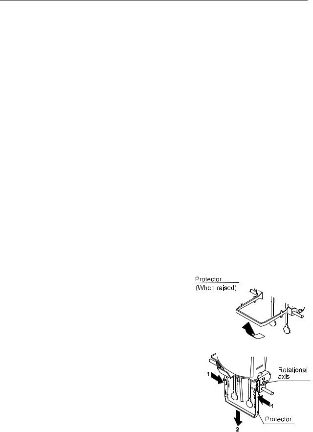
The protector can be raised or removed. So, even when a beaker is used, the viscosity can be measured with a small amount of sample.
How to remove the protector:
Press the left and right side frames lightly in the direction indicated as 1 to remove the rotational axis. Pull the protector in the direction indicated as 2 to remove.
13
4-3 After Use
Remove any residual sample material from the sensor plates, temperature sensor and protector using alcohol. Using the sensor plates, temperature sensor and protector with residue of an old sample left on will cause a measurement error.
Clean the sensor plates carefully to avoid bending them.
The sensor plates and the temperature sensor are made of stainless steel (SUS304). The surface is plated with 24K gold.
Note
Liquids with strong acidity may remove the gold plating and corrode the sensor plates and the temperature sensor.
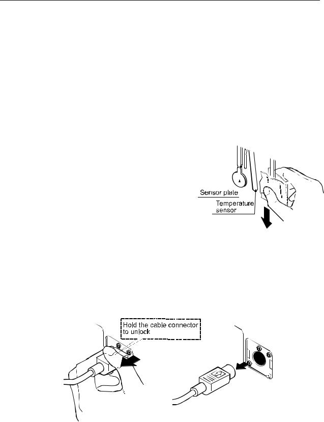
How to clean the sensor plates and temperature sensor
Hold the sensor plate or temperature sensor with tissue paper. Move the tissue paper downward to remove the sample.
Then, use tissue paper moistened with alcohol, to remove any residual sample material.
Clean the sample cup as necessary.
Unlock the cable connector before disconnecting the connection cable.
How to unlock the cable connector
14

4-4 Measuring the Absolute Value of Viscosity
The SV Series Sine-wave Vibro Viscometer, as a measuring principle, detects the product of viscosity and density.
Displayed viscosity value = Viscosity × Density [1]
While the displayed value has a unit of mPa s, it indicates the product of viscosity and density.
Example (1) When a sample has an absolute value of viscosity of 2.00 mPa s and density of 1.000: Displayed value = 2.00 [mPa s] × 1.000
=2.00 [mPa s]
(2)When a sample has an absolute value of viscosity of 2.00 mPa s and density of 0.800: Displayed value = 2.00 [mPa s] × 0.800
=1.60 [mPa s]
Note
The density can be measured, using the density determination kit, AD-1653 in combination with a balance.
To obtain the absolute viscosity value precisely, do as follows:
4-4-1 At Measurement
Divide the displayed viscosity value by the sample density to obtain the absolute value of viscosity.
Example (1) Measure the sample and confirm the displayed viscosity value. Here, 736 mPa s as an example.
(2)Check the sample density at the temperature when the sample is measured. Here, 0.856 as an example.
(3)Divide the displayed viscosity value by the sample density to obtain the absolute value of viscosity.
Here, 860 mPa s is obtained as the absolute viscosity value.
Absolute value of viscosity = |
Displayed viscosity value |
||
|
|
||
Sample density |
|||
|
|||
= |
736 |
860 mPa s |
|
0.856 |
|||
|
|
||
15

4-4-2 At Calibration
When calibrating, enter the product of the absolute viscosity value and the density of the standard viscosity fluid used for calibration, as a correction value.
The standard viscosity fluid has the calculation sheet of kinetic viscosity and viscosity at various temperatures attached. To obtain the correction value using this sheet, do as follows:
Kinetic viscosity = |
Viscosity |
From this, Density = |
Viscosity |
|
[2] |
|
|
||||
Density |
Kinetic viscosity |
Correction value = Viscosity × Density [3]
When substituting [2] for the density in [3], the following equation is obtained.
|
Viscosity2 |
|
Correction value = |
|
[4] |
|
||
|
Kinetic viscosity |
|
Example 1: To calibrate the viscometer using a standard viscosity fluid:
Using the calculation sheet, calculate the value used for calibration.
(1)Check the kinetic viscosity and the viscosity at the temperature when the calibration is performed.
Here, 1011 mm2/s for the kinetic viscosity and 889 mPa s for the viscosity at 20°C as an example.
(2)Substitute the values above into equation [4].
8892 781
1011
781 mPa s is obtained as a correction value used for calibration.
(3)After calibration, measure the viscosity of the standard viscosity fluid used and confirm that the viscometer displays the similar value as the correction value, 781 mPa s in this example. This completes the calibration procedure.
Example 2: To calibrate using a standard viscosity fluid with known values of viscosity and density. In this example, a standard viscosity fluid with a viscosity of 889 mPa s at 20°C is used.
(1)Check the viscosity value and the density of the standard viscosity fluid at the temperature when the calibration is performed..
Here, 889 mPa s for the viscosity and 0.878 for the density at 20°C as an example.
(2)Substitute the values above into equation [3].
889 × 0.878 781
781 mPa s is obtained as a correction value used for calibration.
(3)After calibration, measure the viscosity of the standard viscosity fluid used and confirm that the viscometer displays the similar value as the correction value, 781 mPa s in this example. This completes the calibration procedure.
16
5. MEASUREMENT
5-1 Preparing the Sample
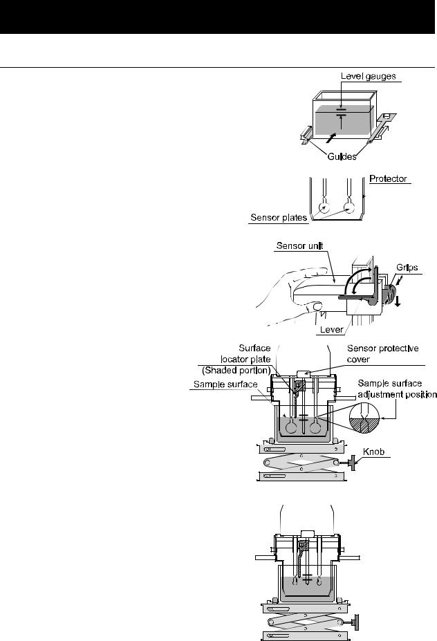
1Pour the sample into the cup until its surface reaches between the level gauges. The level gauges indicate 35 and 45 mL.
2Attach the cup on the table along the guides.
3Confirm that the protector is in the position as shown in the figure.
Raise the lever to release the sensor unit.
4 Pinch the grips, support the front side of the sensor unit and gently lower the sensor plates above the sample surface.
5 Lower the lever to secure the sensor unit.
6 Turn the knob on the table so as to adjust the sample surface to the center of the narrow part of the sensor plates. At this time, use the
surface locator plate as a guide. The surface locator plate has been secured in position so that the tip of the surface locator plate comes into contact with the sample surface.
Note
• Be sure to adjust the sample surface to the center of the narrow part of the sensor plates.
Otherwise, a measurement error may occur.
• The surface locator plate can be attached or removed by loosening the screw.
• Before removing the sensor protective
cover, remove the surface locator plate.
• When the surface locator plate was removed and attached again, it is recommended that calibration be performed using the standard viscosity fluid before measurement.
SV-10
SV-100
17
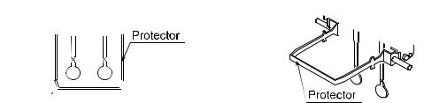
Note
Use the protector in the position as shown on the left below. If the protector is not used with the SV-10, a measurement error may occur, especially in measuring a viscosity over 5000
mPa s.
NO
When the position of the sensor plates in the liquid is not at the same level, level the viscometer using the leveling feet so that the liquid surface will be leveled.
18
 Loading...