


Weighing Indicator
WM+PD4000504
This manual and Marks
All safety messages are identified by the following, “WARNING” or “CAUTION”, of ANSI Z535.4 (American National Standard Institute: Product Safety Signs and Labels). The meanings are as follows:
WARNING |
A potentially hazardous situation which, if not avoided, |
|
could result in death or serious injury. |
||
|
||
CAUTION |
A potentially hazardous situation which, if not avoided, |
|
may result in minor or moderate injury. |
||
|
This is a hazard alert mark.
This manual is subject to change without notice at any time to improve the product.
The product specifications are subject to change without any obligation on the part of the manufacturer.
Under the copyright laws, the instruction manual and the software (program) described in it are copyrighted, with all rights reserved.
2004 |
All rights reserved. |

Contents
1. |
Compliance................................................................................................................................. |
3 |
||
|
1.1.1. Compliance with FCC Rules ..................................................................................... |
3 |
||
|
1.1.2. Compliance with European Directives...................................................................... |
3 |
||
2. |
Introduction ................................................................................................................................. |
4 |
||
3. |
Installation and Precautions....................................................................................................... |
5 |
||
|
3.1.1. |
Installation and Precautions....................................................................................... |
5 |
|
|
3.1.2. The Load Cell Connections ....................................................................................... |
5 |
||
|
3.1.3. Adjustment of the Load Cell Output .......................................................................... |
6 |
||
|
3.1.4. Verifying Load Cell Output and Input Sensitivity ...................................................... |
6 |
||
|
3.1.5. Installing an Option Board.......................................................................................... |
7 |
||
4. |
Description of Panels and symbols........................................................................................... |
8 |
||
|
4.1.1. |
Front Panel Description ............................................................................................. |
8 |
|
|
4.1.2. |
Rear Panel Description.............................................................................................. |
9 |
|
|
4.1.3. Other Displays and Symbols ..................................................................................... |
9 |
||
|
4.1.4. |
Accessories and options.......................................................................................... |
10 |
|
5. |
Calibration................................................................................................................................. |
11 |
||
|
5.1.1. Items of Calibration Mode........................................................................................ |
11 |
||
|
5.2. |
Calibration Procedure ...................................................................................................... |
12 |
|
|
5.2.1. |
Configuring a Weighing Instrument......................................................................... |
12 |
|
|
5.2.2. To Get Stabilized Data............................................................................................. |
14 |
||
|
5.2.3. |
Zero Calibration ........................................................................................................ |
15 |
|
|
5.2.4. |
Span Calibration....................................................................................................... |
15 |
|
|
5.2.5. Exiting the Calibration Mode.................................................................................... |
16 |
||
|
5.3. |
Weighing Range Function ............................................................................................... |
17 |
|
|
5.3.1. Setting the Division and Range............................................................................... |
18 |
||
|
5.4. |
Digital Linearization Function........................................................................................... |
18 |
|
|
5.5. |
Gravity Compensation Function...................................................................................... |
19 |
|
|
5.5.1. The Gravity Acceleration Table............................................................................... |
20 |
||
|
5.6. Calibration Error Code List............................................................................................... |
21 |
||
6. |
Functions .................................................................................................................................. |
22 |
||
|
6.1. Changing the Function Settings ...................................................................................... |
22 |
||
|
6.2. |
F-Functions....................................................................................................................... |
23 |
|
|
6.3. |
CF-Functions .................................................................................................................... |
32 |
|
7. |
Tare |
........................................................................................................................................... |
|
33 |
|
7.1.1. |
Weighing Tare .......................................................................................................... |
33 |
|
|
7.1.2. Digital Input (Preset Tare)........................................................................................ |
33 |
||
|
7.1.3. |
Clearing Tare............................................................................................................ |
33 |
|
8. |
Accumulation ............................................................................................................................ |
34 |
||
|
8.1.1. |
Preparation and Specifications................................................................................ |
34 |
|
|
8.1.2. |
Display and Operation ............................................................................................. |
35 |
|
9. |
Code Memory........................................................................................................................... |
37 |
||
AD-4405 Weighing Indicator, Instruction Manual, A&D Co., ltd. |
|
|||
|
9.1.1. |
Using Code Memory ................................................................................................ |
37 |
|
10. |
Comparison .............................................................................................................................. |
38 |
||
10.1. |
Weight Check Mode......................................................................................................... |
38 |
||
|
10.1.1. |
Condition formula for Comparison .......................................................................... |
39 |
|
|
10.1.2. |
Setting the Upper/Lower Limit Values..................................................................... |
40 |
|
10.2. |
Setpoint Comparison........................................................................................................ |
41 |
||
|
10.2.1. |
Description of Input parameters and Outputs......................................................... |
41 |
|
|
10.2.2. |
Simple Batch............................................................................................................. |
42 |
|
|
10.2.3. |
Setting the Parameters of Setpoint Comparison.................................................... |
43 |
|
11. |
Hold Function............................................................................................................................ |
44 |
||
|
11.1.1. |
Setting the Hold Functions....................................................................................... |
44 |
|
12. |
Counting Function .................................................................................................................... |
46 |
||
12.1. Using the Counting Function ........................................................................................... |
46 |
|||
12.2. |
Unit Weight Registration .................................................................................................. |
46 |
||
13. |
Calendar / Clock....................................................................................................................... |
48 |
||
13.1. Time and Date Functions................................................................................................. |
48 |
|||
13.2. Setting Time and Date ..................................................................................................... |
49 |
|||
14. |
Internal Printer (OP-06)............................................................................................................ |
51 |
||
15. |
Common Printer and Data Output Items ................................................................................ |
53 |
||
15.1. Data Output / Print Mode ................................................................................................. |
53 |
|||
15.2. |
Data Number .................................................................................................................... |
54 |
||
15.3. |
Interval Data Output / Print .............................................................................................. |
54 |
||
|
15.3.1. |
Setting the Interval Time .......................................................................................... |
55 |
|
|
15.3.2. |
Interval Data Output / Print output........................................................................... |
55 |
|
16. |
RS-232C Interface.................................................................................................................... |
56 |
||
16.1. |
Specifications.................................................................................................................... |
56 |
||
16.2. |
Data Format...................................................................................................................... |
57 |
||
16.3. |
Command Format ............................................................................................................ |
58 |
||
|
16.3.1. |
Commands to Request Data................................................................................... |
59 |
|
|
16.3.2. |
Commands to Control the Indicator ........................................................................ |
60 |
|
|
16.3.3. |
Commands to Set Parameters................................................................................ |
62 |
|
|
16.3.4. |
Commands for the Hold Function ........................................................................... |
63 |
|
|
16.3.5. |
Commands to Set the Data Output/ Print Format (UFC) ...................................... |
63 |
|
16.4. |
UFC Commands .............................................................................................................. |
64 |
||
17. |
RS-422/RS-485, Relay Output(OP-03) .................................................................................. |
66 |
||
18. |
Relay Output & Control Input (OP-05) .................................................................................... |
68 |
||
19. |
4-20mA Analog Output (OP-07).............................................................................................. |
69 |
||
20. |
Current Loop Output (OP-08).................................................................................................. |
70 |
||
21. |
Specifications............................................................................................................................ |
72 |
||
21.1. |
Dimensions ....................................................................................................................... |
73 |
||
Page 2 |
AD-4405 Weighing Indicator |
1. Compliance
1.1.1.Compliance with FCC Rules
Please note that this equipment generates, uses and can radiate radio frequency energy. This equipment has been tested and has been found to comply with the limits of a Class A computing device pursuant to Subpart J of Part 15 of FCC rules. These rules are designed to provide reasonable protection against interference when this equipment is operated in a commercial environment. If this unit is operated in a residential area it may cause some interference and under these circumstances the user would be required to take, at his own expense, whatever measures are necessary to eliminate the interference.
(FCC = Federal Communications Commission in the U.S.A.)
1.1.2.Compliance with European Directives
This appliance complies with the statutory EMC (Electromagnetic Compatibility) directive 89/336/EEC and the Low Voltage Directive 73/23/EEC for safety of electrical equipment designed for certain voltages.
Note: The displayed value may be adversely affected under extreme electromagnetic influences.
AD-4405 Weighing Indicator |
Page 3 |
1. Compliance |
2.Introduction
The AD-4405 is a weighing indicator that amplifies signals from a load cell, converts it to digital data and displays it as a mass value.
This indicator has the following performance:
Input sensitivity: ......................... 0.25 mV/division.
Maximum display: ...................... 40000 divisions.
Refresh rate of the display: ........ 10 times/second approximately.
Input voltage range: ................... -1 mV ~ +15 mV.
The following standard functions are available:
The HiHi / Hi / OK / Lo / LoLo limit comparison to check a mass value. The setpoint comparison for batching applications.
The counting function for piece counting.
The preset tare function.
There are four code memories to store the above mentioned data.
The accumulation function to totalize these mass values and to count the number of accumulations.
The hold function enables weighing a living animal.
UFC (Universal Flex Coms) function to customize the protocol of the printing format as well as outputting data using the serial interface.
0 - 9 keys enables easy operation, such as setting of comparator values. Built-in calendar clock with backup battery.
There are the following interfaces:
One interface can be installed in the indicator at a time.
An RS-232C serial interface is standard, to communicate with a computer, printer or a remote display. This interface outputs data and can request weight data, enter parameters and control the state of the indicator.
RS-422/485 and 3-Relay Outputs (Option: OP-03)
RS-232C, 3-Relay Outputs and 3-Control Inputs (Option: OP-05)
RS-232C, Current Loop Output, 3-Relay Outputs and 1-Control Input (Option: OP-08)
Analog Output (4-20mA) (Option: OP-07)
There is optional dot matrix impact printer. (OP-06)
The calibration function includes the following functions:
Setting of the minimum division (weighing interval) and the maximum capacity. Zero and span calibration.
The weighing range function of the multi-interval weighing instrument (scale). Digital linearization function.
Gravity compensation function.
2. Introduction Page 4 AD-4405 Weighing Indicator
3. Installation and Precautions
3.1.1.Installation and Precautions
The AD-4405 weighing indicator is a precision electronic instrument. Handle the indicator carefully.
The operating temperature is -10°C to +40°C (14°F to 104°F).
Do not install the scale in direct sunlight.
Mis-operation or other problems may be caused by an unstable power source including momentary power failure or instantaneous noise. Use a stable power source.
Do not connect the power cord before the installation has been completed. Verify that the local voltage and receptacle type are correct for your scale.
Use shielded cable for all connections. Connect the cable shields to the shield terminal or case as an earth terminal.
Earth ground the indicator. Do not join the earth ground line with other electrical power equipment. There is an earth ground terminal at the power cord receptacle. Do not install the indicator in a place where it is apt to be charged with static electricity, or where the relative humidity is lower than 45%RH. Plastic and insulating materials are apt to be charged with static electricity.
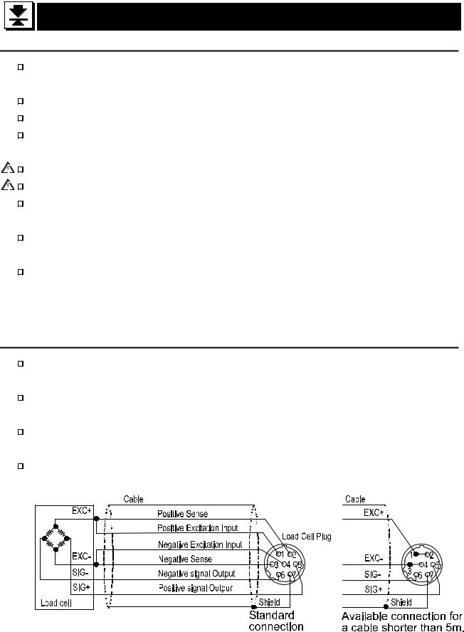
3.1.2.The Load Cell Connections
Connect the load cell wires to the connector (receptacle), at the rear panel, using the accessory load cell plug.
It is possible to connect a 4 wire cable provided that pins 1-2 and pins 3-4 are shorted, if the distance between the indicator and the load cell is shorter than 5m. The output voltage of a load cell is a very sensitive signal. Space the load cell cable away from any noise source.
It is possible to connect four 350ohm load cells.
The load cell drive is 5VDC  5% between EXC+ and EXC-, the maximum current 60mA.
AD-4405 Weighing Indicator |
Page 5 |
3. Installation and Precautions |
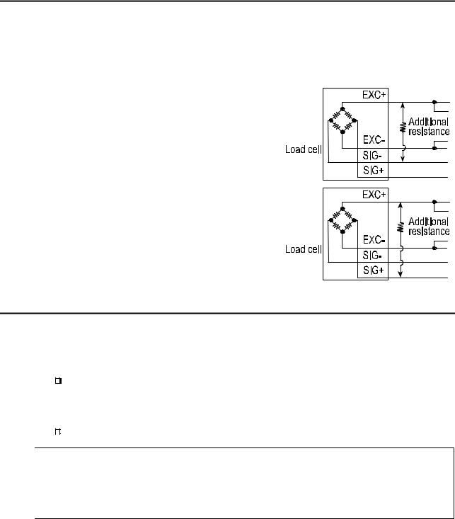
3.1.3.Adjustment of the Load Cell Output
Caution 
 Use a metal film resistor in the range of 50kohm to 500kohm with a good temperature coefficient, when adding a resistor to adjust a load cell output. Use as large of a resistance value as possible in the range in which the zero adjustment is possible. Solder this resistor at a point near the load cell or the indicator.
In Case of Reducing the Output Voltage
When the zero output is too large, add a resistor between EXC+ and SIG-.
In Case of Adding an Offset Voltage to the Output
When the zero output is too small, add a resistor between EXC+ and SIG+.
3.1.4.Verifying Load Cell Output and Input Sensitivity
The input sensitivity of the indicator is 0.25mV /division or more. Adapt to the following inequality, when you design a weighing instrument using the indicator and load cell(s).
Caution
|
|
|
|
|
|
E * B * D |
|
|
Weighing instrument |
|
0.25 £ |
|
|||
|
|
|
|||||
|
using one load cell. |
A |
|
||||
|
|
|
|
||||
|
|
|
|
|
|
||
|
Weighing instrument |
|
0.25 £ |
E * B * D |
|
||
|
using multi-load cell |
A* N |
|
||||
|
|
|
|
||||
|
|
|
|
|
|
|
|
A:Rated capacity of load cell [kg]
B:Rated output [mV/V]
D:Weighing interval [kg]
E:Excitation voltage [mV]
N:Number of load cells
Verification Example
|
Design: |
|
|
|
|
|
|
|
|
Load cell |
N=1 |
|
5000 |
* 3 * 0.05 |
|
|
|
|
Rated capacity |
A=750 [kg] |
|
= 1 ³ 0.25 |
. Therefore, |
|||
|
|
|
|
|
||||
|
|
750 |
||||||
|
Rated output |
B=3 [mV/V] |
|
|
|
|
|
|
|
|
regard the instrument as a good |
||||||
|
Excitation voltage |
E=5000 [mV] |
|
|||||
|
|
design. |
|
|||||
|
Weighing interval |
D=0.05 [kg] |
|
|
||||
|
|
|
|
|
|
|
||
|
Weighing capacity |
300 [kg] |
|
|
|
|
|
|
3. Installation and Precautions |
Page 6 |
|
|
|
AD-4405 Weighing Indicator |
|||

3.1.5.Installing an Option Board
This is the procedure for the data output board (OP-03, OP-05, OP-07 and OP-08).
Caution |
|
|
Do not remove any screws without the following step. |
|
|
||
|
|
||
Step 1 |
Remove the power cord from the power outlet (mains) and other cables from the |
||
indicator.
Step 2 Remove two screws from the RS-232C panel at rear panel.
Step 3 Remove the standard RS-232C panel and board from the indicator. Step 4 Remove the cable from the standard RS-232C board.
Step 5 Connect the cable that was removed in step 4 to the new option board. Please be careful to orientate the connector correctly.
Step 6 If the option board has an earth terminal (OP-05, OP-08), connect the earth cable in the indicator to that terminal.
Step 7 Insert the option board into the indicator.
Step 8 Secure option board panel using two screws.
Step 9 Set the F-Function(s).
OP-07 : f30 1 (Analog output)
OP-08 : f37 if current loop output is used
AD-4405 Weighing Indicator |
Page 7 |
3. Installation and Precautions |
4. Description of Panels and symbols
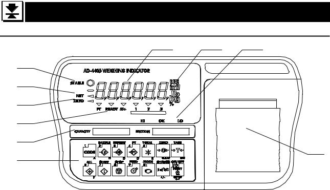
4.1.1.Front Panel Description
5 |
6 |
7 |
1
2
3
4
8
10
9
N |
Name |
|
Description |
|
o. |
|
|
||
|
|
|
|
|
1 |
STABLE |
Indicates when the display is stable. |
|
|
2 |
NET |
Indicates when the display is the net weight. |
||
3 |
ZERO |
Indicates when the display weight is in the Zero range. |
||
4 |
Annunciator |
lndicates various weighing status or functional selection. |
||
|
PT |
Indicates when PRESET TARE value is being used. |
||
|
READY |
Indicates the state of comparison or batching. |
||
|
M+ (Accumulation) |
Indicates when there is a result of addition or accumulation. |
||
|
1,2,3(Triangle) |
Depending on the function selected, Indicates various states. |
||
5 |
MAIN display |
Displays the weight, accumulation data or setting parameters. |
||
6 |
UNIT part |
Unit used to weigh. |
|
|
7 |
HI/OK/LO |
Indicates the results of comparison. |
|
|
8 |
Capacity label |
Capacity and division (this label is included in the accessories). |
||
9 |
Key switches |
Selects the display, settings or data output. |
||
|
CODE key |
The key to select the code memory. |
|
|
|
SAMPLE key |
The key to set the unit weight for the counting function. |
||
|
SETPOINT key |
The key to set the comparator value. |
|
|
|
PT key |
The key to set the PRESET TARE value. |
|
|
|
TOTAL key |
The key to display the total weight. |
|
|
|
M+ key |
The key to display the total weight. |
|
|
|
START key |
The key to start comparison / batch weighing. |
||
|
STOP key |
The key to stop comparison / batch weighing. |
||
|
FEED key |
The key to feed the paper of the optional Built-in Printer. |
||
|
MODE key |
The key to switch unit used to weigh. |
|
|
|
0 – 9 key |
The key to input any numerical settings. |
|
|
|
A – F key |
Used to enter setting values (press NET/GROSS key at a time). |
||
4. Description of Panels and symbols |
Page 8 |
AD-4405 Weighing Indicator |
||
|
ZERO key |
The key to zero the current display. |
|
CLEAR key |
The key to clear the setting value. |
|
TARE key |
The key to perform tare. |
|
ESC key |
The key to proceed to the next step without changing the |
|
parameter set. |
|
|
|
|
|
NET/GROSS key |
The key to select net or gross weight in the display. |
|
+/- key |
The key to select + or – of a value. |
|
ENTER key |
Confirms settings and stores the value. |
|
PRINT key |
The key to print/output data (press and release quickly). |
|
ON/OFF key |
Turns the indicator on and off (OFF: hold for 3 seconds). |
10 |
Printer cover |
Printing paper will be stored inside when the printer is installed. |
|
Printer |
Internal dot matrix printer (optional). |
4.1.2.Rear Panel Description
12 |
13 |
14 |
15
11
16
No. |
Name |
Description |
|
11 |
Power cable |
Please confirm that the local voltage and receptacle type are |
|
correct for your scale. |
|||
|
|
||
12 |
Grounding terminal |
Connect to the Earth (M4 size screw). |
|
13 |
Load cell connector |
Connect a load cell using the accessory load cell plug. |
|
14 |
CAL switch cover |
The CAL switch is located behind the sealing panel [15]. |
|
15 |
Sealing panel |
For type approval, available with the sealing wire posts. |
|
16 |
RS-232C connector |
Exchange this when installing other data output (options). |
4.1.3.Other Displays and Symbols
Standby display.
Zero error when turning the display on. If the ESC key is pressed, the current weighing value may should be displayed.
Over load display. Remove any load from the load cell immediately. It may cause damage to the load cell.
An example of an error display.
AD-4405 Weighing Indicator |
Page 9 |
4. Description of Panels and symbols |

4.1.4.Accessories and options
Standard accessories
|
|
|
|
|
Instruction manual |
1 |
|
|
|
|
|
|
Load cell plug |
1 |
JM-NJC-207-PF |
|
Accessories |
|
0.2A or 0.315A time lag fuse |
1 |
FS-EAWK-200MA |
||
|
|
|
|
FS-EAWK-315MA |
|||
|
|
|
|
|
|
|
|
|
|
|
|
|
Capacity label |
1 |
|
|
|
|
|
|
Function seal |
1 |
|
Caution |
Please confirm that the receptacle type and local voltage is correct for |
||||||
|
|
|
your indicator (scale). |
|
|
||
Options |
|
|
|
|
|
||
|
OP-03 (AD-4405-03) * |
RS-422/485 interface, 3-Relay outputs |
|
||||
|
OP-05 (AD-4405-05) * |
RS-232C interface, 3-Relay outputs and 3-Control inputs |
|||||
|
OP-06 |
(AD-4405-06) |
Built-in dot matrix impact printer (16 characters/line) |
||||
|
OP-07 |
(AD-4405-07) * |
4-20mA analog output |
|
|
||
|
OP-08 |
(AD-4405-08) * |
RS-232C interface, 20mA current loop output, 3-Relay outputs |
||||
|
|
|
|
and 1-Control input |
|
|
|
|
OP-10 |
(AD-4405-10) |
Panel mount kit |
|
|
||
|
|
|
|
(Panel attachment and load cell input terminal block) |
|||
*Only one interface option can be installed at a time, by exchanging with the standard RS-232C interface.
Supplemental accessories (for printer)
Print paper |
AX-PP-156-S (10 rolls) |
Ink Ribbon |
AX--EWRC05-S (5pcs.) |
4. Description of Panels and symbols |
Page 10 |
AD-4405 Weighing Indicator |
5. Calibration
This indicator, converts an input voltage from a load cell to the "mass" value, and
displays it. Calibration is the adjustment function so that the scale (indicator) can
display the weight correctly.
5.1.1.Items of Calibration Mode
There are four items in the calibration function where setting should be done.
How to calibrate: In the weighing mode, press the CAL key. After Cal in is displayed for
2 seconds Cal 0 will appear. Then the required items should be selected and displayed
with the MODE key, then executed by pressing the ENTER key.
NOTE: Calibration could be started by simultaneously pressing the ZERO and TARE keys,
instead of the CAL key. However, in some cases, the procedures are altered to nullify
this option. Furthermore, this option is not available with sealed type version setting.
Required Items
Cal5et Store capacity, resolution, alignment of decimal point position and display format, weighing range and unit. These items should be set first in order for the indicator to function as a weighing instrument. Set values do not need to be changed again unless the indicator itself is replaced. For details, refer to “5.2.1. Setting a Weighing Instrument”.
Cal 0 Calibrates zero and span. This is required after installation, to get accurate data. For details, refer to “5.2.3. Zero Calibration” and “5.2.4. Span Calibration”.
Optional Items (Sub-functions)
lnr 0 Performs digital linearization. Refer to “5.4. Digital Linearization Function”.
g 5et Compensates for acceleration of gravity. Refer to “5.5. Gravity Compensation Function”.
Gravity compensation function: Compensates for weighing error between the calibration location and another weighing location using gravity acceleration.
In the calibration mode the keys have functions as follows:
0 - 9 Numerical keys.
MODE The key to display other items.
CLEAR The cancel key at inputting data, initial data and changing mode.
+/- |
The key to display other parameters. |
ESC The key to proceed to the next step without changing set values.
ENTER The key to store new calibration data and proceeds to the next step.
CAL The key to store all of the parameters into memory and display Caloff after
the calibration mode. Press the ON/OFF key to turn off the display.
AD-4405 Weighing Indicator |
Page 11 |
5. Calibration |
Note that the ON/OFF key does not function alone. Press the ESC key while holding the ON/OFF key to end the calibration mode, if mis-operation. After displaying Can5el, press the ON/OFF key to end the calibration mode and turn the indicator off.
NOTE: When displaying Caloff , press the +/- key while pressing the ON/OFF key, instead of CAL key. However, in some cases, settings are altered to nullify this option.
Caution |
|
The maximum display is less than or equal to 40000 divisions. This number |
|
||
|
||
|
|
is calculated from the maximum capacity divided by the minimum division. |
|
|
Check the accuracy of the weighing instrument periodically. |
|
|
|
|
|
|
|
|
Recommended mass, use a mass heavier than 2/3 maximum capacity. |
|
|
|
|
|
|
|
|
Calibrate the scale, if it is moved to another location or the environment |
|
|
|
|
|
|
|
|
has changed. |
|
|
It is not necessary to set the gravity acceleration correction, when calibrating |
|
|
|
|
|
|
|
|
the scale with a calibration mass at the place where the scale is used. |
|
|
Enter the stable weighing data while the STABLE mark is displayed. If |
|
|
|
|
|
|
|
|
unstable data is used, it may cause a weighing error. Arrange the |
|
|
condition using the F00 filter function. |
|
|
The span calibration needs the zero calibration data. We recommend |
|
|
|
|
|
|
|
|
that you perform the span calibration immediately after the zero |
|
|
calibration. |
|
|
If you use the dual range function of the multi-interval scale, perform the |
|
|
|
|
|
|
|
|
"Range Function", "Zero Calibration" and "Span Calibration". |
5.2. Calibration Procedure
5.2.1.Configuring a Weighing Instrument
This section explains how to set capacity, resolution, decimal point position and display format, weighing range and unit. Perform this procedure when installing the indicator.
When Cal5et appears on the display, enter the setting mode by pressing of the ENTER key.
Setting the range and unit.
Single Range
Select the resolution, decimal point position and format.
¯
Specify the weighing capacity.
5. Calibration |
Page 12 |
AD-4405 Weighing Indicator |
Dual Range
<First range> Select the resolution, decimal point position and format.
¯
<First range> Select the weighing range
¯
<Second range> Select the resolution
¯
<Second Range> Specify the weighing capacity
For the range function, refer to “5.3. Weighing Range Function”.
Specifying the Range and Unit
Step 1 The range and unit of measure are displayed.
Range display : |
5ingl |
: single range |
|||||||
|
|
|
|
|
|
|
|
|
|
|
|
|
dUal |
: dual range |
|||||
|
|
|
|
|
|
|
|||
|
|
To change the range function, use the |
CLEAR |
key |
|||||
Unit display: |
The active unit is displayed. When using units that can be |
||||||||
|
|
|
used interchangeably, such as kg or lb, calibration should be |
||||||
|
|
|
done by using the displayed unit. |
||||||
|
|
|
|
|
|||||
|
|
To select a unit for weighing, use the |
MODE |
key and to select unit for |
|||||
|
|
calibration, use the +/- key. The unit for calibration (first unit) is |
|||||||
|
|
displayed and the alternate unit (second unit) is blinking. |
|||||||
|
|
Stores the value displayed and then advances to the next step. |
|||||||
ENTER |
|||||||||
|
|
Advances to the next step without changing the parameter. |
|||||||
ESC |
|
||||||||
Specifying the Resolution, Decimal Point Position and Format
Step 2 The resolution will be displayed as d 01., with decimal point. Triangle 1 and the first unit selected at the previous step will be displayed.
Positioning of the decimal point is done with the CLEAR key, setting of display format (point or comma) with the +/- key, the resolution with the MODE key. The decimal point format, set at this stage, will only apply to the display. The decimal point format for serial data output is selected using the F-function settings.
Press the ENTER key to store the displayed settings and then proceed to the next step. Using the ESC key, regardless of what is displayed, the indicator will proceed to the next step without changing the set data.
AD-4405 Weighing Indicator |
Page 13 |
5.2. Calibration Procedure |
Specifying the Weighing Range of the First Range
Step 3 After displaying Cap for 2 seconds, the first range or the weighing capacity of single range will be displayed. When dual range is used, Cap1 is displayed for 2 seconds. Triangle  1 will be displayed. Specify parameter with the 0 - 9 keys and press the ENTER key to store it and proceed to the next step. When pressing the ESC key, regardless of what is displayed, the indicator will proceed to the next step without changing the parameters. The next step is Zero Calibration in single range or the second range resolution in dual range.
Specifying the Second Range Resolution
Step 4 After displaying range2 for 2 seconds, the resolution with decimal point and triangle
 2 will be displayed. Specify the second range resolution in the same way as the first range. The decimal point cannot be moved. Specify the second range resolution greater than the first range. Press the ENTER key to store the parameters and proceed to the next step. When pressing the ESC key, regardless of what is displayed, the indicator will proceed to the next step without changing the parameter.
Specifying the Second Range Capacity
Step 5 After displaying Cap2 for 2 seconds, the capacity with unit and decimal point is displayed. Specify the capacity in the same way as the first range. The capacity should be greater than the first range. Press the ENTER key to store the parameters and proceed to Zero Calibration.
5.2.2.To Get Stabilized Data
Step 6 Maintain the following conditions to calibrate the scale (indicator) correctly.
Maintain a constant temperature, stable power and stable input voltage from the load cell.
Avoid direct sunshine or the near the outlet of an air conditioner.
Do not install the scale (indicator) where there is a strong magnetic field.
Step 7 Turn the display on and leave it for several minutes.
5.2. Calibration Procedure |
Page 14 |
AD-4405 Weighing Indicator |
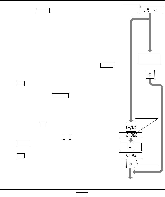
5.2.3.Zero Calibration
Procedure
Step 8 Check the Cal 0 display.
Zero calibration
Select a zero calibration method to adjust the zero point
Weighing input |
The adjustment method |
|
|
with nothing on the |
To step 9 |
||
(Normal way) |
|||
weighing unit. |
|
||
|
|
||
|
The numerical way to |
|
|
Digital input |
enter a load cell output |
To step 10 |
|
|
voltage. |
|
Weighing Input
Step 9 Place nothing on the weighing unit. Press the ENTER key after the STABLE mark has turned ON. The new zero point parameter will be stored. Proceed to step11.
ESC key ..........The key not to change the zero point data and proceed to the next step.
Caution: Do not press the ENTER key while the STABLE mark is off (detecting motion). Arrange the condition using the F00 filter function.
Digital Input
Step10 Pressing the +/- key, a stored input voltage parameter of the zero point is displayed in the unit of mV/V. Adjust the input voltage using the 0 - 9 keys.
ENTER.......The key to store the zero point parameter
Place nothing on the weighing unit (No load)
Turn on STABLE mark
ENTER
Stored input voltage
NET/GROSS
+/-
mV/V
and proceed to the next step.
ESC key.....The key to proceed to the next step without changing the parameter.
0 9
mV/V
New input voltage |
|
ENTER |
|
To Span Calibration
5.2.4.Span Calibration
Step11 Check the capacity display after Cal f is displayed for 2 seconds.
Select a span calibration method to adjust the capacity.
Weighing a mass less than the |
The method to weigh a mass less |
To step 12 |
|
maximum capacity |
than the maximum capacity. |
||
|
|||
Weighing a maximum capacity |
The method to weigh a mass |
To step 14 |
|
mass |
equivalent to the maximum capacity. |
||
|
|||
Digital input |
The numerical way to enter a load |
To step 16 |
|
cell output voltage. |
|||
|
|
AD-4405 Weighing Indicator |
Page 15 |
5.2. Calibration Procedure |
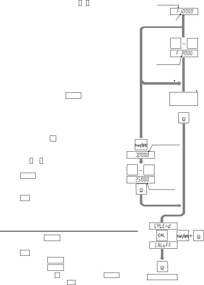
Weighing a Mass less than the Maximum Capacity
Step12 |
Set a mass value using the 0 - 9 keys. |
Step13 |
Place a mass equivalent to the displayed value |
|
on the weighing unit. Proceed to step 15. |
Weighing a Maximum Capacity Mass
Step14 Place a mass equivalent to the maximum capacity on the weighing unit.
Step15 Press the |
ENTER |
key after the |
STABLE |
||
mark turns on. Proceed to step17. |
|
||||
|
|
|
The key to proceed to step17 |
||
|
ESC |
..........key |
|||
without changing the span parameters.
Caution:Do not press the ENTER key while the STABLE mark is off (detecting motion). Arrange the condition using the F00 filter function.
Digital Input
Step16 Pressing the +/- key, a stored input voltage parameter of the span is displayed in the unit of mV/V. Adjust the input voltage using the 0 - 9 keys. (It is possible to store a greater value than the capacity.)
ENTER key......The key to store the span parameters and proceed to step 17.
ESC key ..........The key to proceed to step 17 without changing the span parameters.
Span calibration
Maximum capacity
To step 14, step 16
To step 12
0 9
New mass value
Mass of maximum capacity
|
|
step 13 |
|
|
|
To step 14 |
step 14 |
|
|
|
|
Place the displayed To step 16 mass on the
weighing unit
Turn on STABLE mark
ENTER
NET/GROSS
Stored input voltage
|
+/- |
|
mV/V |
0 |
9 |
mV/V
New input voltage |
|
ENTER |
|
5.2.5.Exiting the Calibration Mode
Step17 Check the Calend display.
Use the following keys.
CAL key ..... To store the parameters and display Caloff. Proceed to the next step.
Caloff could be displayed by pressing the +/- key while pressing the ON/OFF key instead of CAL key.
NET/GROSS
or
+/- ENTER
ENTER
Turn display off
5.2. Calibration Procedure |
Page 16 |
AD-4405 Weighing Indicator |
ESC key ..... The key to store the parameters temporarily. Proceed to the Cal 0 display.
Press and hold the ON/OFF key and press the ESC key
No parameters are changed, CanCel is displayed and the calibration mode is finished.
Step18 Press the ON/OFF key to turn the display off.
5.3. Weighing Range Function
The weighing range function can select "single range" or "dual range". Specify each weighing interval (division) for the multi-interval instrument. Each weighing interval is displayed according to a net value or gross value.
Caution |
|
|
When single range is used, performing this function is not required. |
||||||||||||||||||||||||||||||||||||||||
|
|
||||||||||||||||||||||||||||||||||||||||||
|
|||||||||||||||||||||||||||||||||||||||||||
Example 1 |
|
|
|
|
The gross display. |
|
|
|
|
|
|
|
|||||||||||||||||||||||||||||||
Specified parameters: |
|
|
|
|
|
|
|
|
|
|
|
|
|
|
|
|
|
|
|
|
|
|
|
|
|
|
|
|
|||||||||||||||
|
|
|
|
|
First range |
|
|
Range = 50.00kg, division 0.02kg |
|
||||||||||||||||||||||||||||||||||
|
|
|
|
|
Second range |
|
|
Range = 100.00kg (maximum capacity), division 0.1kg |
|||||||||||||||||||||||||||||||||||
Display |
|
|
|
|
|
|
|
|
|
|
|
|
|
|
|
|
|
|
|
|
|
|
|
|
|
|
|
|
|||||||||||||||
|
|
|
|
|
0kg to 50kg : |
|
|
The first range, division 0.02kg. |
|
|
|
|
|
|
|
||||||||||||||||||||||||||||
|
|
|
|
|
50kg to 100kg : |
|
|
The second range, division 0.1kg. |
|
||||||||||||||||||||||||||||||||||
|
|
|
|
|
|
|
|
|
|
|
|
|
|
|
|
|
|
|
|
|
|
|
|
|
|
|
|
|
|
|
|
|
|
|
|
|
|
|
|
|
|
|
|
|
|
|
|
|
|
|
Division = 0.02kg |
|
|
|
|
|
|
|
|
|
|
|
|
|
|
|
|
|
|
|
|
|
|||||||||||||||
|
|
|
|
|
|
|
|
|
|
|
|
|
|
|
|
|
|
|
|
|
|
|
|
|
|
|
|
Division = 0.1kg |
|
||||||||||||||
0kg |
|
|
|
|
|
|
|
|
|
|
|
|
|
|
|
|
50kg |
|
|
|
100kg Gross |
||||||||||||||||||||||
|
|
|
|
|
|
|
|
|
|
|
|
|
|
|
|
|
|
|
|
|
|
|
|
|
|
|
|
|
|
|
|
|
|
|
|
|
|
|
|
|
|
||
|
|
|
|
|
|
|
|
|
|
|
|
|
|
|
|
|
|
|
|
|
|
|
|
|
|
|
|
|
|
|
|
|
|
|
|
|
|
|
Weighing value |
||||
Example 2 |
|
|
|
|
The net display using a 40kg tare value. |
|
|
|
|
|
|
|
|||||||||||||||||||||||||||||||
Specified parameters: |
|
|
The same parameters as example 1. |
|
|||||||||||||||||||||||||||||||||||||||
Display |
|
|
|
|
|
|
|
|
|
|
|
|
|
|
|
|
|
|
|
|
|
|
|
|
|
|
|
|
|||||||||||||||
|
|
|
|
|
-40kg to 50kg : |
|
|
The first range, division 0.02kg. |
|
|
|
|
|
|
|
||||||||||||||||||||||||||||
|
|
|
|
|
50kg to 60kg : |
|
|
The second range, division 0.1kg. |
|
||||||||||||||||||||||||||||||||||
|
|
|
|
|
|
|
|
|
|
|
|
|
|
|
|
Division = 0.02kg |
|
|
|
|
|
|
|
||||||||||||||||||||
|
|
|
|
|
|
|
|
|
|
|
|
|
|
|
|
|
|
|
|
|
|
|
|||||||||||||||||||||
|
|
|
|
|
|
|
|
|
|
|
|
|
|
|
|
|
|
|
|
|
|
|
|
|
|
|
|
|
|
|
|
|
|
|
|
|
|
|
Division=0.1kg |
||||
|
|
-40kg |
|
|
0kg |
|
50kg 60kg |
|
Net |
||||||||||||||||||||||||||||||||||
|
|
|
|
|
|
|
|
|
|
|
|
|
|
|
|
|
|
|
|
|
|
|
|
|
|
|
|
|
|
|
|
|
|
|
|
|
|
|
Gross |
||||
|
|
|
|
|
|
|
|
|
|
|
|
|
|
|
|
Tare value |
|
90kg 100kg |
|||||||||||||||||||||||||
|
|
|
|
|
|
|
|
|
|
|
|
|
|
|
|
40kg |
Weighing value |
|
|||||||||||||||||||||||||
AD-4405 Weighing Indicator |
Page 17 |
5.3. Weighing Range Function |
5.3.1.Setting the Division and Range
Consider the following rules to design the weighing range.
Rule 1 Select the division and range of each weighing range so as to fit the following inequality. The first range < the second range
The division of the next weighing range is automatically set larger than the division of the lower weighing range. And the division can change.
Rule 2 When setting the dual range, the upper limit value of the second range becomes the maximum capacity.
Rule 3 Select a resolution smaller than 40000. The resolution is a value that divides the maximum capacity by the minimum division of the first range.
5.4. Digital Linearization Function
Even if the zero and span calibration have been completed, there may still remain a linearity deviation caused by the performance of the weighing unit. The digital linearization function can rectify or reduce the linearity deviation using weighing points during the zero and capacity setting. Up to three weighing points can be specified.
Caution |
|
This function does not improve repeatability or hysteresis. |
|
||
|
||
|
|
Use the mass on the condition that lnr 1 < lnr 2 < lnr 3. |
|
|
|
|
|
Do not press the ENTER key while the STABLE mark is off.
Step 1 |
Check the |
Cal 0 |
display. Press the |
MODE |
key to display |
lnr 0 |
. |
Step 2 |
Enter the zero point. Refer to “5.2.3. Zero Calibration”. |
||||||
|
|
|
|
|
|
|
|
|
|
Step 3 |
The value of the middle point is displayed after indicating |
lnr x. x is 1, 2 or 3. |
|||||||
|
|
|
The triangle |
|
|
|
|
|
|
|
|
|
mark of the same number(x) is displayed along with the value. |
||||||
Step 4 Select a middle point. |
|||||||||
|
|
|
|
|
|
|
|||
|
|
|
If you want to cancel the current procedure, press the |
ESC |
key to finish this |
||||
|
|
|
|||||||
|
|
|
|||||||
|
|
|
function. Proceed to step 7 and other points are cleared (canceled). |
||||||
|
|
|
Select a middle point value using the 0 - 9 keys. Proceed to step 5. |
||||||
|
|
|
|||||||
|
|
|
|||||||
Step 5 |
Place a mass equivalent to the displayed value on the weighing unit. Press the |
||||||||
|
|
|
|
|
|||||
|
|
|
ENTER |
key after the STABLE mark has turned on. Proceed to step 6. |
|||||
Step 6 |
If you include a 2nd and 3rd middle point, repeat steps 3, 4, 5 for each. |
||||||||
|
|
|
If you finish this function, proceed to step 7. |
||||||
Step 7 |
Perform step 11 of "5.2.4. Span Calibration" immediately. |
||||||||
5.4. Digital Linearization Function |
Page 18 |
AD-4405 Weighing Indicator |
5.5. Gravity Compensation Function
If the scale is used at the calibration location, it is not necessary to perform this function. If there is a difference of gravity acceleration between the installed location and calibration location it may cause a weighing error. This function specifies the gravity accelerations and corrects the span error.
Note |
|
The decimal point is not displayed in the function. Example: |
9798 |
= 9.798 m/s2 |
|
||||
|
||||
|
|
When span calibration is executed, the gravity acceleration correction will |
||
|
|
|||
|
|
|||
|
|
be cleared and the two gravity acceleration values will return to the factory |
||
|
|
settings. |
||
Step 1 At the Cal 0 display, press the MODE key twice, g 5et is displayed and press the
ENTER key to enter the gravity compensation function.
If you want to cancel the current procedure, press and hold the ON/OFF key and press the ESC key. Then, no parameters are changed and the calibration mode is finished. Press the ON/OFF key to turn the display off after displaying CanCel.
Step 2 The parameter is displayed with triangle 1. Enter the gravity acceleration of the calibration location using the 0 - 9 keys. The parameter xxxx is the gravity acceleration.
ENTER key...The key to store the new gravity acceleration and proceed to step 3.
ESC key .......The key to return to g 5et without changing the value.
Step 3 The parameter is displayed with triangle 2. Enter the gravity acceleration of the installed location using the 0 - 9 keys. The parameter xxxx is the gravity acceleration.
ENTER key...The key to store the new gravity acceleration and proceed to step 4.
ESC key .......The key to return to step 2 without changing the value.
Step 4 Now g xxxx is displayed. Press the CAL key to store the parameters. Caloff is displayed. Proceed to step5.
Caloff could be displayed by pressing the +/- key while pressing the ON/OFF key instead of the CAL key.
Step 5 Press the ON/OFF key to turn the display off.
AD-4405 Weighing Indicator |
Page 19 |
5.5. Gravity Compensation Function |

5.5.1.The Gravity Acceleration Table
|
Amsterdam |
9.813 |
m/s2 |
Manila |
9.784 |
m/s2 |
||||||||||||
|
Athens |
9.800 |
m/s2 |
Melbourne |
9.800 |
m/s2 |
||||||||||||
|
Auckland NZ |
9.799 |
m/s2 |
Mexico City |
9.779 |
m/s2 |
||||||||||||
|
Bangkok |
9.783 |
m/s2 |
Milan |
9.806 |
m/s2 |
||||||||||||
|
Birmingham |
9.813 |
m/s2 |
New York |
9.802 |
m/s2 |
||||||||||||
|
Brussels |
9.811 |
m/s2 |
Oslo |
9.819 |
m/s2 |
||||||||||||
|
Buenos Aires |
9.797 |
m/s2 |
Ottawa |
9.806 |
m/s2 |
||||||||||||
|
Calcutta |
9.788 |
m/s2 |
Paris |
9.809 |
m/s2 |
||||||||||||
|
Chicago |
9.803 |
m/s2 |
Rio de Janeiro |
9.788 |
m/s2 |
||||||||||||
|
Copenhagen |
9.815 |
m/s2 |
Rome |
9.803 |
m/s2 |
||||||||||||
|
Cyprus |
9.797 |
m/s2 |
San Francisco |
9.800 |
m/s2 |
||||||||||||
|
Djakarta |
9.781 |
m/s2 |
Singapore |
9.781 |
m/s2 |
||||||||||||
|
Frankfurt |
9.810 |
m/s2 |
Stockholm |
9.818 |
m/s2 |
||||||||||||
|
Glasgow |
9.816 |
m/s2 |
Sydney |
9.797 |
m/s2 |
||||||||||||
|
Havana |
9.788 |
m/s2 |
Tainan |
9.788 |
m/s2 |
||||||||||||
|
Helsinki |
9.819 |
m/s2 |
Taipei |
9.790 |
m/s2 |
||||||||||||
|
Kuwait |
9.793 |
m/s2 |
Tokyo |
9.798 |
m/s2 |
||||||||||||
|
Lisbon |
9.801 |
m/s2 |
Vancouver, BC |
9.809 |
m/s2 |
||||||||||||
|
London (Greenwich) |
9.812 |
m/s2 |
Washington DC |
9.801 |
m/s2 |
||||||||||||
|
Los Angeles |
9.796 |
m/s2 |
Wellington NZ |
9.803 |
m/s2 |
||||||||||||
|
Madrid |
9.800 |
m/s2 |
Zurich |
9.807 |
m/s2 |
||||||||||||
|
|
|
|
|
|
|
|
|
|
|
|
|
|
|
|
|
|
|
|
|
|
|
|
|
|
|
|
|
|
|
|
|
|
|
|
|
|
|
|
|
|
|
|
|
|
|
|
|
|
|
|
|
|
|
|
|
|
|
|
|
|
|
|
|
|
|
|
|
|
|
|
|
|
|
|
|
|
|
|
|
|
|
|
|
|
|
|
|
|
|
|
|
|
|
|
|
|
|
|
|
|
|
|
|
|
|
|
|
|
|
|
|
|
|
|
|
|
|
|
|
|
|
|
|
|
|
|
|
|
|
|
|
|
|
|
|
|
|
|
|
|
|
|
|
|
|
|
|
|
|
|
|
|
|
|
|
|
|
|
|
|
|
|
|
|
|
|
|
|
|
|
|
|
|
|
|
|
|
|
|
|
|
|
|
|
|
|
|
|
|
|
|
|
|
|
|
|
|
|
|
|
|
|
|
|
|
|
|
|
|
|
|
|
|
|
|
|
|
|
|
|
|
|
|
|
|
|
|
|
|
|
|
|
|
|
|
|
|
|
|
|
|
|
|
|
|
|
|
|
|
|
|
|
|
|
|
|
|
|
|
|
|
|
|
|
|
|
|
|
|
|
|
|
|
|
|
|
|
|
|
|
|
|
|
|
|
|
|
|
|
|
|
|
|
|
|
|
|
|
|
|
|
|
|
|
|
|
|
|
|
|
|
|
|
|
|
|
|
|
|
|
|
|
|
|
|
|
|
|
|
|
|
|
|
|
|
|
|
|
|
|
|
|
|
|
|
|
|
|
|
|
|
|
|
|
|
|
|
|
|
|
|
|
|
|
|
|
|
|
|
|
|
|
|
|
|
|
|
|
5.5. Gravity Compensation Function |
Page 20 |
AD-4405 Weighing Indicator |

5.6. Calibration Error Code List
Exiting from a Calibration error
ESC key..... The key to return to the point where an error occurred. Retry the operation.
ESC key while pressing the ON/OFF key.
No parameters are changed, CanCel is displayed and the calibration mode is finished. Press the ON/OFF key to turn the display off.
Error Code List
If an error has occurred during the calibration mode, the following code is displayed.
Error code |
Description |
|
|
|
|
err 0 |
In multi-interval scale. The last division is set to maximum ( d-50 ). |
|
Therefore the next division can not be entered. |
||
|
||
|
Resolution exceeds 40000. (Resolution = maximum capacity/ minimum |
|
err 1 |
division) |
|
|
Reduce the maximum capacity or increase the minimum division. |
|
err 2 |
Load cell output is too large or too small at zero calibration. Check the weighing |
|
unit and load cell. Refer to "3.1.4.Verifying Load Cell Output and Input |
||
err 3 |
||
Sensitivity". |
||
|
||
err 4 |
Measuring calibration mass, the value exceeded maximum capacity. Reduce |
|
the calibration mass. |
||
|
||
err 5 |
The selected calibration mass is smaller than the minimum division. |
|
err 6 |
The new input sensitivity is less than 0.2 µV/division. Increase the input |
|
sensitivity. Refer to "3.1.4.Verifying Load Cell Output and Input Sensitivity". |
||
|
||
|
Placing a mass on the weighing unit, the load cell output becomes a negative |
|
err 7 |
value. Check the load cell cable connections and the direction of load cell |
|
|
mounting. |
|
|
The load cell output exceeds the input range before the maximum capacity. |
|
err 8 |
Adjust zero balance referring to "3.1.4.Verifying Load Cell Output and Input |
|
Sensitivity". Replace with a load cell designed for a smaller output. Reduce |
||
|
||
|
maximum capacity. |
|
err 9 |
The weight value is out of the input range at zero calibration or span |
|
calibration. Check the weighing unit and cables. |
||
|
||
err 12 |
The first weighing range is larger than second weighing range. |
|
err 13 |
An incorrect mass was selected at the digital linearization function. |
|
Select a mass of the following relation. Lnr 1 < Lnr 2 < Lnr 3. |
||
|
||
g err |
An unacceptable value was selected in the gravity acceleration function. |
AD-4405 Weighing Indicator |
Page 21 |
5.6. Calibration Error Code List |
6. Functions
There are two parameters lists, one for the F-functions and one for the CF-functions. These functions control the indicator. The parameters of each function are stored in non-volatile memory, and are not lost even if power is turned off or cut off.
F-functions: These parameters can always be changed and are used for internal settings. CF-functions: If you accept a certificated approval of the weighing instruments, the CAL cover (rear panel) must be sealed. Therefore, accepting this approval, the
parameters of the CF-function can not be changed.
6.1. Changing the Function Settings
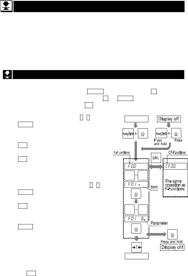
To enter the function settings, do either of the following.
1.When the display is off, press the ON/OFF key while pressing the +/- key.
2.When in the weighing mode, press both the +/- and ON/OFF keys at the same time.
When you are in the function setting, f00 will be displayed. |
|
|
|
||
Operating Item |
|
|
|
|
|
Step 1 Select an item using the 0 - 9 keys. |
Weighing |
|
|
||
|
|
|
|
||
ENTER key |
The key to display a parameter of |
|
|
|
|
|
the selected item. |
NET/GROSS |
NET/GROSS |
||
|
|
|
|||
|
|
|
|
|
|
|
Proceed to step 2. |
+/- |
ENTER |
+/- |
ENTER |
|
|
|
|
|
|
ESC key |
To end function setting and enter |
|
|
|
|
|
the weighing mode. |
|
|
|
|
CAL key |
The key to exchange F-functions |
|
|
|
|
|
and CF-functions. |
|
|
|
|
Operating parameter
Step 2 Select a parameter using the 0 - 9 keys.
ENTER key The key to store a parameter and return to step 1.
The key to return step 1 without changing the parameter.
Change the display as default value.(Type1)
Change sub item.(Type2, Type3)
0 |
9 |
ENTER
0 9
ENTER |
|
|
ENTER |
TARE
Type2 and Type3 are indicated in the
|
ESC |
parameter table. |
Weighing |
|
Exit function setting
Press ESC key to go to the weight display when item number is displayed.
6. Functions |
Page 22 |
AD-4405 Weighing Indicator |
 Loading...