

Page 1
Instructions for Vacuum
Gauge/Pressure Tester
Cranking Vacuum Test For
Engine Condition
1. Start Engine and warm to normal
operating temperature.
2. Turn engine off and disable ignition.
3. Remove air filter and back out idle
speed screw counting turns until
throttle valve is closed.
NOTE: If carburetor is equipped with an idle
air bleed screw, turn clockwise, counting
number of turns until screw bottoms lightly.
NOTE: If vehicle is equipped with an
idle stop solenoid, disconnect electrical
wires at base of solenoid under rubber
boot or at connector.
NOTE: If vehicle is equipped with a PCV
(Positive Crankcase Ventilation) system,
remove valve at engine rocker arm cover
and plug valve on bottom with tape.
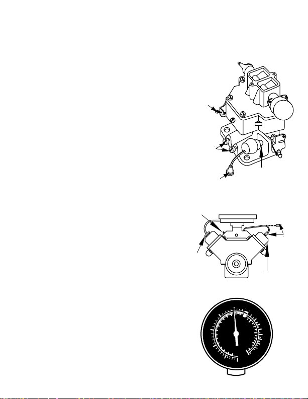
4. Using hose supplied, connect Vacuum
Gauge to fitting on carburetor below
throttle plate or a fitting on intake
manifold.
5. Crank engine and note Vacuum
Gauge reading.
6. Return adjustment screws to original
positions.
Test Results
3 possible gauge readings are:
A.Steady vacuum reading of the following
indicates correct engine vacuum:
4 inches or more on emission
controlled engines.
10 inches or more on non-emission
controlled engines
Idle
Speed
Screw
Idle
Mixture
Screw
Electrical
Connector
Manifold
Closed
Breather
Air Cleaner
Vacuum
Cap
10
Engine
Vacuum
15
20
25
Steady Vacuum of 4
inches or more
5
0
Fuel
Pump
7
30
Idle Stop
Solenoid
Rocker Arm
Valve Cover
0
1
2
3
1
2
4
3
5
psi
4
6
5
6
7
8
9
10
PCV
Valve
Page 2
NOTE: See Manufacturers Specifications.
B.Really low, steady vacuum check for:
Leaking carburetor flange gasket
Worn carburetor throttle shaft
Leaking vacuum lines
Improper valve timing
Slow engine cranking due to:
- Battery or cable connections
- Defective starter motor
Mechanical drag in engine due to:
- Tight fitting pistons in rebuilt engine
- Thickened oil due to excessive
oxidation
C.Pulses unsteady indicates a leaky
condition that affects one or more
cylinders check for:
Burned or stuck valve
Intake manifold leak at a cylinder
Worn intake valve guide
Broken piston or piston rings
NOTE: A certain amount of even pulsing
is normal, notably on 4 and 6 cylinder
engines, and does not necessarily
indicate a leaky condition.
Running Vacuum Test For
Engine Condition
NOTE: It is possible to get a different gauge
reading than obtained during the Cranking
Vacuum Test For Engine Condition.
1. Using hose supplied, connect
Vacuum Gauge to fitting on
carburetor below throttle plate.
2. Start Engine and let idle until at
normal operating temperature.
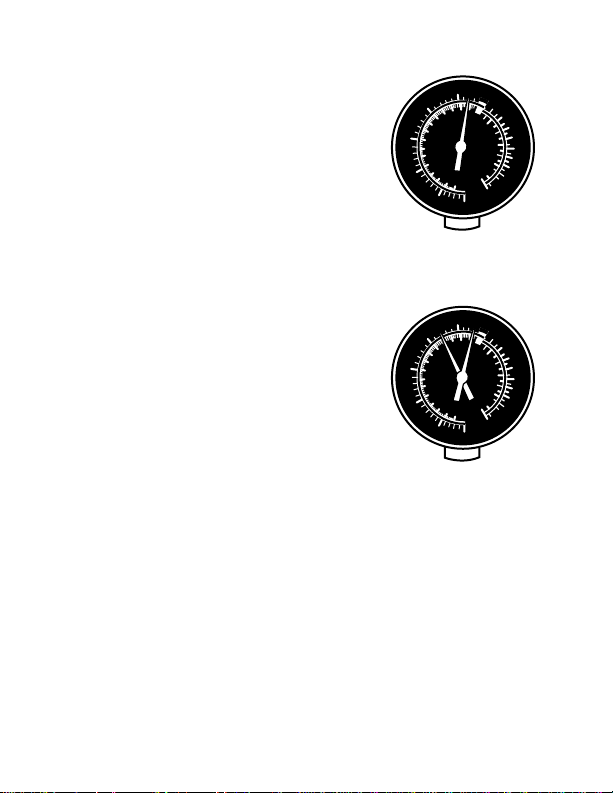
Test Results
2 possible gauge readings are:
5
0
10
Engine
Vacuum
15
20
25
1
0
1
2
3
Fuel
Pump
4
5
6
7
10
30
Steady low vacuum
5
0
10
Engine
Vacuum
15
20
25
1
0
1
2
3
Fuel
Pump
4
5
6
7
10
30
Unsteady vacuum
2
3
4
5
psi
6
7
8
9
2
3
4
5
psi
6
7
8
9
Page 3

A. Steady vacuum reading between 15
and 20 inches indicates a mechanically
sound engine.
B.If unsteady reading increase engine
speed to 2000 RPM:
If evens out check:
- Ignition and/or timing
- Carburetor mixture adjustments at idle
If pointer sweeps get larger check for
- Weak or broken valve springs
If pointer sweeps become smaller
and more rapid check for:
- Carburetor or intake manifold leaks
- Sticky valves
Exhaust Restriction Test
1. Make sure vacuum gauge is connected.
2. Increase engine speed to 2000 RPM
and keep.
3. Note vacuum gauge reading.
4. Look for slowly decreasing vacuum
reading.
If vacuum decreases check for a
partially blocked muffler or tailpipe.
Positive Crankcase Ventilation
(PCV) Valve Test
1. Unplug PCV valve that was plugged
with tape.
2. Crank engine
If vacuum drops to half the noted
vacuum then the PCV valve is good.
If vacuum reading is much lower than
one-half the problem is usually
excessive flow which could upset the
proper carburetor air/fuel ratio causing
rough idling and burned valves.
If vacuum does not change the PCV
valve is usually clogged.
5
0
10
Engine
Vacuum
15
20
25
Steady vacuum between
15 and 20 inches
10
Engine
Vacuum
15
20
25
1
2
0
3
1
2
4
3
Fuel
5
psi
Pump
4
6
5
6
7
7
8
9
10
30
5
0
1
2
0
3
1
2
4
3
Fuel
5
psi
Pump
4
6
5
6
7
7
8
9
10
30
Unsteady vacuum reading
5
0
Engine
1
2
0
3
1
2
4
3
Fuel
5
psi
Pump
4
6
5
6
7
7
8
9
10
30
10
Vacuum
15
20
25
Vacuum Drops half the
noted vacuum
Page 4

3. Return idle screw and idle air bleed
screws to original positions, if required.
4. Re-enable the ignition system
5. Reconnect wire to idle stop solenoid.
6. Reconnect all hoses and vacuum lines.
7. Reinstall PCV valve.
Idle
Speed
Screw
Distributor Vacuum Advance
Mechanisms
1. Disconnect hose from distributor
2. Insert a tee connector in line with
hose and another back to distributor.
3. Connect gauge to the tee connector.
4. Start engine and note vacuum at idle.
5. Slowly increase RPM noting vacuum
pressure.
Test Results
2 possible results are:
A. Vacuum manifold pressure should
drop as engine speed is increased
per vehicle manual
B. If vacuum manifold pressure does not
change or changes very little check for:
Vacuum hose being opened or
cracked
Diaphragm in advance mechanism
punctured.
NOTE: Vacuum reading can appear
normal during the above test but still
have a bad advance mechanism that is
frozen due to corrosion or dirt.
Fuel Pump Testing
Fuel Pump Testing can be done using
the 0-10 psi scale on the gauge. Make
sure to follow manufacturers
instructions exactly and follow all safety
precautions.
©2004 Actron Manufacturing Company. All rights reserved. 0002-003-1862
Idle
Mixture
Screw
Electrical
Connector
Manifold
Closed
Breather
Air Cleaner
Vacuum
Cap
5
10
Engine
Vacuum
15
20
25
30
Using Fuel Pump Scale
Rocker Arm
Valve Cover
0
1
0
1
2
3
Fuel
Pump
4
5
6
7
10
Idle Stop
Solenoid
2
3
4
5
psi
6
7
8
9
PCV
Valve
 Loading...