

Page 1
CP9185
CP9190
Elite AutoScanner
®
Elite AutoScanner® Pro
P/N 0002-001-2933
Page 2

Scan Tool Information
Complete the following list using
the function “Tool Information”.
Provide this information when
contacting customer support.
Serial No:
SW ID:
HW Ver:
Boot Ver:
Prod ID:
Board ID:
Burn Date:
Burn Loc:
If you have questions or concerns Contact
Technical Support:
•Phone: 1-800-228-7667
•Website: www.actron.com
•Mail:SPX Service Solutions
• 15825 Industrial Parkway
• Cleveland, Ohio 44135
• Attn: Technical Support
Copyright Information
Copyright © 2006-2007 SPX Corporation
All rights reserved.
The information, specifications and illustrations in this
guide are based on the latest information available at the
time of printing. SPX Corporation reserves the right to
make changes at any time without notice.
Page 3

Table of Contents
Safety Precautions
Important Safety Messages . . . . . . . . . . . . . . . . . . . . . . . . . . . . . . . Safety - iii
Section 1 – Using This Manual
Section 2 – Getting Started
Introduction . . . . . . . . . . . . . . . . . . . . . . . . . . . . . . . . . . . . . . . . . . . . . . . . . 2-1
Using the CD . . . . . . . . . . . . . . . . . . . . . . . . . . . . . . . . . . . . . . . . . . . . . . . . 2-2
Installing Applications On Included CD . . . . . . . . . . . . . . . . . . . . . . . . .. 2-3
Vehicle Service Information . . . . . . . . . . . . . . . . . . . . . . . . . . . . . . . . . . . . 2-4
Introduction to On-Board Diagnostics . . . . . . . . . . . . . . . . . . . . . . . . . . . . 2-6
SAE Publications . . . . . . . . . . . . . . . . . . . . . . . . . . . . . . . . . . . . . . . . . .. 2-7
Data Link Connector (DLC) . . . . . . . . . . . . . . . . . . . . . . . . . . . . . . . . . . . . . 2-9
OBD II (J1962) . . . . . . . . . . . . . . . . . . . . . . . . . . . . . . . . . . . . . . . . . . . .. 2-9
Ford Historic . . . . . . . . . . . . . . . . . . . . . . . . . . . . . . . . . . . . . . . . . . . .. 2-10
GM Historic . . . . . . . . . . . . . . . . . . . . . . . . . . . . . . . . . . . . . . . . . . . . .. 2-13
Chrysler Historic . . . . . . . . . . . . . . . . . . . . . . . . . . . . . . . . . . . . . . . . .. 2-14
OBD II Diagnostic Trouble Codes (DTCs) . . . . . . . . . . . . . . . . . . . . . . . . 2-15
ToC
Section 3– Using The Scan Tool
The Scan Tool . . . . . . . . . . . . . . . . . . . . . . . . . . . . . . . . . . . . . . . . . . . . . . . 3-1
Specifications . . . . . . . . . . . . . . . . . . . . . . . . . . . . . . . . . . . . . . . . . . . . . .3-2
Accessories for the Scan Tool . . . . . . . . . . . . . . . . . . . . . . . . . . . . . . . . .3-3
Display . . . . . . . . . . . . . . . . . . . . . . . . . . . . . . . . . . . . . . . . . . . . . . . . . . .3-4
Keypad . . . . . . . . . . . . . . . . . . . . . . . . . . . . . . . . . . . . . . . . . . . . . . . . . .3-4
Power . . . . . . . . . . . . . . . . . . . . . . . . . . . . . . . . . . . . . . . . . . . . . . . . . . .3-5
Scan Tool Power UP. . . . . . . . . . . . . . . . . . . . . . . . . . . . . . . . . . . . . . . . . . . 3-7
System Setup . . . . . . . . . . . . . . . . . . . . . . . . . . . . . . . . . . . . . . . . . . . . . . . . 3-7
Changing Measurement Units . . . . . . . . . . . . . . . . . . . . . . . . . . . . . . . . .3-8
Changing Display Contrast . . . . . . . . . . . . . . . . . . . . . . . . . . . . . . . . . . .3-9
Beeper . . . . . . . . . . . . . . . . . . . . . . . . . . . . . . . . . . . . . . . . . . . . . . . . . .3-10
Changing Auto-Power Off . . . . . . . . . . . . . . . . . . . . . . . . . . . . . . . . . . .3-11
View Tool Information . . . . . . . . . . . . . . . . . . . . . . . . . . . . . . . . . . . . . .3-12
Display Test . . . . . . . . . . . . . . . . . . . . . . . . . . . . . . . . . . . . . . . . . . . . . .3-13
Keyboard Test . . . . . . . . . . . . . . . . . . . . . . . . . . . . . . . . . . . . . . . . . . . .3-15
Memory Test. . . . . . . . . . . . . . . . . . . . . . . . . . . . . . . . . . . . . . . . . . . . . .3-15
Program Mode . . . . . . . . . . . . . . . . . . . . . . . . . . . . . . . . . . . . . . . . . . . .3-17
Connecting The Scan Tool. . . . . . . . . . . . . . . . . . . . . . . . . . . . . . . . . . . . . 3-17
Review Data . . . . . . . . . . . . . . . . . . . . . . . . . . . . . . . . . . . . . . . . . . . . . .3-18
Playback . . . . . . . . . . . . . . . . . . . . . . . . . . . . . . . . . . . . . . . . . . . . . . . . .3-19
Print Data . . . . . . . . . . . . . . . . . . . . . . . . . . . . . . . . . . . . . . . . . . . . . . . .3-21
i
Page 4

Code Lookup. . . . . . . . . . . . . . . . . . . . . . . . . . . . . . . . . . . . . . . . . . . . . 3-23
Setup User Key. . . . . . . . . . . . . . . . . . . . . . . . . . . . . . . . . . . . . . . . . . . 3-26
Vehicle Selection . . . . . . . . . . . . . . . . . . . . . . . . . . . . . . . . . . . . . . . . . 3-27
Section 4 – Global OBD II Diagnostics
Global OBD II Diagnostics . . . . . . . . . . . . . . . . . . . . . . . . . . . . . . . . . . . . . . 4-1
ToC
Global Function List . . . . . . . . . . . . . . . . . . . . . . . . . . . . . . . . . . . . . . . . . . . 4-2
Datastream Menu . . . . . . . . . . . . . . . . . . . . . . . . . . . . . . . . . . . . . . . . . . . . . 4-3
View Data . . . . . . . . . . . . . . . . . . . . . . . . . . . . . . . . . . . . . . . . . . . . . . . . 4-4
Record Data . . . . . . . . . . . . . . . . . . . . . . . . . . . . . . . . . . . . . . . . . . . . . . 4-9
Diagnostic Codes Menu . . . . . . . . . . . . . . . . . . . . . . . . . . . . . . . . . . . . . . . 4-12
Read Codes . . . . . . . . . . . . . . . . . . . . . . . . . . . . . . . . . . . . . . . . . . . . . 4-12
Pending Codes . . . . . . . . . . . . . . . . . . . . . . . . . . . . . . . . . . . . . . . . . . 4-14
Erase Codes . . . . . . . . . . . . . . . . . . . . . . . . . . . . . . . . . . . . . . . . . . . . 4-16
View Freeze Data . . . . . . . . . . . . . . . . . . . . . . . . . . . . . . . . . . . . . . . . 4-18
Special Tests Menu. . . . . . . . . . . . . . . . . . . . . . . . . . . . . . . . . . . . . . . . . . . 4-19
I/M Readiness . . . . . . . . . . . . . . . . . . . . . . . . . . . . . . . . . . . . . . . . . . . 4-20
Drive Cycle Monitor . . . . . . . . . . . . . . . . . . . . . . . . . . . . . . . . . . . . . . . 4-23
State OBD Check . . . . . . . . . . . . . . . . . . . . . . . . . . . . . . . . . . . . . . . . . 4-26
O2 Monitor Test . . . . . . . . . . . . . . . . . . . . . . . . . . . . . . . . . . . . . . . . . . 4-27
Diagnostic Monitor Tests . . . . . . . . . . . . . . . . . . . . . . . . . . . . . . . . . . . 4-30
On-Board Systems . . . . . . . . . . . . . . . . . . . . . . . . . . . . . . . . . . . . . . . . 4-33
Vehicle Info . . . . . . . . . . . . . . . . . . . . . . . . . . . . . . . . . . . . . . . . . . . . . 4-34
Modules Present . . . . . . . . . . . . . . . . . . . . . . . . . . . . . . . . . . . . . . . . . 4-37
Section 5 – GM Diagnostics
GM Historic (OBD I) Diagnostics . . . . . . . . . . . . . . . . . . . . . . . . . . . . . . . . . 5-1
GM Function List. . . . . . . . . . . . . . . . . . . . . . . . . . . . . . . . . . . . . . . . . . . 5-1
Datastream Menu . . . . . . . . . . . . . . . . . . . . . . . . . . . . . . . . . . . . . . . . . . . . . 5-2
View Data . . . . . . . . . . . . . . . . . . . . . . . . . . . . . . . . . . . . . . . . . . . . . . . . 5-3
Record Data . . . . . . . . . . . . . . . . . . . . . . . . . . . . . . . . . . . . . . . . . . . . . . 5-4
Diagnostic Codes Menu . . . . . . . . . . . . . . . . . . . . . . . . . . . . . . . . . . . . . . . . 5-6
Read Codes . . . . . . . . . . . . . . . . . . . . . . . . . . . . . . . . . . . . . . . . . . . . . . 5-7
Erase Codes . . . . . . . . . . . . . . . . . . . . . . . . . . . . . . . . . . . . . . . . . . . . . . 5-8
Special Tests Menu. . . . . . . . . . . . . . . . . . . . . . . . . . . . . . . . . . . . . . . . . . . 5-10
Field Service . . . . . . . . . . . . . . . . . . . . . . . . . . . . . . . . . . . . . . . . . . . . . 5-11
GM Enhanced (OBD II) Diagnostics. . . . . . . . . . . . . . . . . . . . . . . . . . . . . . 5-14
GM Function List for OBD II . . . . . . . . . . . . . . . . . . . . . . . . . . . . . . . . . 5-16
Diagnostic Codes Menu . . . . . . . . . . . . . . . . . . . . . . . . . . . . . . . . . . . . . . . 5-16
Read Codes . . . . . . . . . . . . . . . . . . . . . . . . . . . . . . . . . . . . . . . . . . . . . 5-16
Erase Codes . . . . . . . . . . . . . . . . . . . . . . . . . . . . . . . . . . . . . . . . . . . . . 5-18
Section 6 – Ford Diagnostics
Ford Historic (OBD I) Diagnostics. . . . . . . . . . . . . . . . . . . . . . . . . . . . . . . . 6-1
Ford Function List . . . . . . . . . . . . . . . . . . . . . . . . . . . . . . . . . . . . . . . . . . 6-1
Datastream Menu . . . . . . . . . . . . . . . . . . . . . . . . . . . . . . . . . . . . . . . . . . . . . 6-3
View Data . . . . . . . . . . . . . . . . . . . . . . . . . . . . . . . . . . . . . . . . . . . . . . . . 6-3
Record Data . . . . . . . . . . . . . . . . . . . . . . . . . . . . . . . . . . . . . . . . . . . . . . 6-4
ii
Page 5

Diagnostic Codes Menu . . . . . . . . . . . . . . . . . . . . . . . . . . . . . . . . . . . . . . . . 6-6
Read KOEO Codes . . . . . . . . . . . . . . . . . . . . . . . . . . . . . . . . . . . . . . . . .6-7
Read KOER Codes . . . . . . . . . . . . . . . . . . . . . . . . . . . . . . . . . . . . . . . . .6-9
Erase Codes. . . . . . . . . . . . . . . . . . . . . . . . . . . . . . . . . . . . . . . . . . . . . .6-13
IVSC-Speed Ctrl (EEC_IV Vehicles) . . . . . . . . . . . . . . . . . . . . . . . . . . .6-16
On Demand Test Menu. . . . . . . . . . . . . . . . . . . . . . . . . . . . . . . . . . . . . . . . 6-19
Wiggle Test (EEC_IV Vehicles) . . . . . . . . . . . . . . . . . . . . . . . . . . . . . . .6-20
Output Switch Test (EEC_IV Vehicles) . . . . . . . . . . . . . . . . . . . . . . . . .6-22
Cylinder (Cyl) Balance Test (EEC_IV Vehicles) . . . . . . . . . . . . . . . . . . .6-24
STAR Test Mode (EEC_IV, MECS and MCU Vehicles). . . . . . . . . . . . .6-27
Ford Enhanced (OBD II) Diagnostics . . . . . . . . . . . . . . . . . . . . . . . . . . . . 6-29
Ford Function List. . . . . . . . . . . . . . . . . . . . . . . . . . . . . . . . . . . . . . . . . .6-29
Diagnostic Codes Menu . . . . . . . . . . . . . . . . . . . . . . . . . . . . . . . . . . . . . . . 6-31
Read Codes . . . . . . . . . . . . . . . . . . . . . . . . . . . . . . . . . . . . . . . . . . . . . .6-31
Section 7 – Chrysler Diagnostics
Chrysler Diagnostics . . . . . . . . . . . . . . . . . . . . . . . . . . . . . . . . . . . . . . . . . . 7-1
Chrysler Function List. . . . . . . . . . . . . . . . . . . . . . . . . . . . . . . . . . . . . . . .7-1
Datastream Menu . . . . . . . . . . . . . . . . . . . . . . . . . . . . . . . . . . . . . . . . . . . . . 7-4
View Data . . . . . . . . . . . . . . . . . . . . . . . . . . . . . . . . . . . . . . . . . . . . . . . .7-4
Record Data . . . . . . . . . . . . . . . . . . . . . . . . . . . . . . . . . . . . . . . . . . . . . . .7-6
Sensor Test . . . . . . . . . . . . . . . . . . . . . . . . . . . . . . . . . . . . . . . . . . . . . . .7-7
Diagnostic Codes Menu . . . . . . . . . . . . . . . . . . . . . . . . . . . . . . . . . . . . . . . . 7-8
Read Codes . . . . . . . . . . . . . . . . . . . . . . . . . . . . . . . . . . . . . . . . . . . . . . .7-8
Erase Codes. . . . . . . . . . . . . . . . . . . . . . . . . . . . . . . . . . . . . . . . . . . . . .7-10
Device Controls Menu . . . . . . . . . . . . . . . . . . . . . . . . . . . . . . . . . . . . . . . . 7-11
Switch Test . . . . . . . . . . . . . . . . . . . . . . . . . . . . . . . . . . . . . . . . . . . . . . .7-11
Actuator Test . . . . . . . . . . . . . . . . . . . . . . . . . . . . . . . . . . . . . . . . . . . . .7-12
Idle Speed Test . . . . . . . . . . . . . . . . . . . . . . . . . . . . . . . . . . . . . . . . . . .7-14
ToC
Section 8 – Import Diagnostics
Import (OBD II) Diagnostics. . . . . . . . . . . . . . . . . . . . . . . . . . . . . . . . . . . . . 8-1
Import Function List . . . . . . . . . . . . . . . . . . . . . . . . . . . . . . . . . . . . . . . . .8-1
Diagnostic Codes Menu . . . . . . . . . . . . . . . . . . . . . . . . . . . . . . . . . . . . . . . . 8-2
Read Codes . . . . . . . . . . . . . . . . . . . . . . . . . . . . . . . . . . . . . . . . . . . . . . .8-3
Section 9 – Troubleshooting
How to Use On-Line Help. . . . . . . . . . . . . . . . . . . . . . . . . . . . . . . . . . . . . . . 9-1
Error Messages. . . . . . . . . . . . . . . . . . . . . . . . . . . . . . . . . . . . . . . . . . . . . . . 9-2
Scan Tool Does Not Power Up . . . . . . . . . . . . . . . . . . . . . . . . . . . . . . . . . . 9-2
Vehicle Communication Fault . . . . . . . . . . . . . . . . . . . . . . . . . . . . . . . . . . . 9-3
Operating Error or Erroneous Data . . . . . . . . . . . . . . . . . . . . . . . . . . . . . . 9-4
Battery Replacement . . . . . . . . . . . . . . . . . . . . . . . . . . . . . . . . . . . . . . . . . . 9-5
Tool Self-Tests . . . . . . . . . . . . . . . . . . . . . . . . . . . . . . . . . . . . . . . . . . . . . . . 9-6
Technical Support. . . . . . . . . . . . . . . . . . . . . . . . . . . . . . . . . . . . . . . . . . . . . 9-6
Appendix A – PID Definitions
Appendix B – Data Link Connectors
iii
Page 6

Appendix C – Glossary
ToC
iv
Page 7
Safety Precautions
For your safety, read this manual thoroughly before operating your
Scan Tool. Always refer to and follow safety messages and test
procedures provided by the manufacturer of the vehicle or equipment
being tested.
The safety messages presented below and throughout this user’s
manual are reminders to the operator to exercise extreme care when
using this test instrument.
Read All Instructions
Read, understand and follow all safety messages and instructions in
this manual and on the test equipment. Safety messages in this section
of the manual contain a signal word with a three-part message and, in
some instances, an icon.
Safety Messages
Safety messages are provided to help prevent personal injury and
equipment damage. All safety messages are introduced by a signal
word. The signal word indicates the level of the hazard in a situation.
The types of safety messages are.
!
DANGER
!
WARNING
!
!
CAUTION
IMPORTANT
• • • • • • • • • • • • • • • • • • • • • • • • • • • • • • • • • • • • • • • • • • • • • • • • • • • • • • Safety – i
Indicates a possible hazardous situation which, if not
avoided, will result in death or serious injury to
operator or bystanders.
Indicates a possible hazardous situation which, if not
avoided, could result in death or serious injury to
operator or bystanders.
Indicates a possible hazardous situation which, if not
avoided, may result in moderate or minor injury to
operator or bystanders.
Indicates a condition which, if not avoided, may result
in damage to test equipment or vehicle.
Page 8
Safety Precautions
!
Type Styles Used:
Safety messages contain three different type styles.
• Normal type states the hazard.
• Bold type states how to avoid the hazard.
• Italic type states the possible consequences of not avoiding the
hazard.
Icons used:
An icon, when present, gives a graphical description of a potential
hazard.
Example:
Engine systems can malfunction expelling fuel, oil
vapors, hot steam, hot toxic exhaust gases, acid,
refrigerant and other debris.
Safety goggles and protective gloves must be worn
by the operator and any bystanders. Even if everyday
eyeglasses have impact resistant lenses, they are
NOT safety glasses.
Engine systems that malfunction can cause injury.
Safety – ii • • • • • • • • • • • • • • • • • • • • • • • • • • • • • • • • • • • • • • • • • • • • • • • • • • • • •
Page 9
Safety Precautions
Important Safety Messages
Risk of electric shock.
• Do not exceed voltage limits between inputs
indicated in the Specifications.
• Use extreme caution when working with circuits that
have voltage greater than 60 volts DC or 24 volts
AC.
Electric shock can cause injury.
Risk of explosion.
• Safety goggles and protective clothing must be
worn by the operator and any bystanders.
!
WARNING
- Even if everyday glasses have impact resistant
lenses, they are NOT safety glasses, and may not
provide adequate protection.
• Do not use this scan tool in environments where
explosive vapors may collect. These areas include:
- below-ground pits.
- confined areas.
- areas that are less than 18 inches above floor.
!
• Use this Scan Tool in locations with mechanical
ventilation providing at least 4 air changes per hour.
• Flammable fuel and vapors can ignite.
• Do not smoke, strike a match, or cause a spark in
the vicinity of the battery. Battery gases can ignite.
• • • • • • • • • • • • • • • • • • • • • • • • • • • • • • • • • • • • • • • • • • • • • • • • • • • • • Safety – iii
Page 10
Safety Precautions
!
WAR NI N G
!
• Avoid making an accidental connection between the
battery terminals. Do not place uninsulated metal
tools on the battery.
• When removing battery cables, remove the ground
cable first.
• Avoid sparks when connecting or disconnecting
power leads to the battery.
• Make sure ignition is off, headlights and other
accessories are off and vehicle doors are closed
before disconnecting the battery cables.
-
This also helps prevent damage to on-board computer systems.
• Always disconnect the battery ground connections
before servicing electrical system components.
Explosion can cause injury.
Risk of poisoning.
• Use this Scan Tool in locations with mechanical
ventilation providing at least 4 air changes per hour.
Engine exhaust contains odorless gas which can be
lethal.
• Route the exhaust outside while testing with the
engine running.
Poisoning can result in death or serious injury.
Safety – iv • • • • • • • • • • • • • • • • • • • • • • • • • • • • • • • • • • • • • • • • • • • • • • • • • • • •
Page 11

Safety Precautions
!
WARNING
Battery acid is a highly corrosive sulfuric acid.
• Safety goggles and protective gloves must be worn
by the operator and any bystanders.
- Even if your everyday glasses have impact resistant
lenses, they are NOT safety glasses, and may not
provide adequate protection.
• Make sure someone can hear you or is close enough
to provide aid when working near a battery.
• Have plenty of fresh water and soap nearby.
- If battery acid contacts skin, clothing, or eyes, flush
exposed area with soap and water for 10 minutes.
Seek medical help.
• Do not touch eyes while working near battery.
Battery acid can burn eyes and skin.
!
• • • • • • • • • • • • • • • • • • • • • • • • • • • • • • • • • • • • • • • • • • • • • • • • • • • • • Safety – v
Page 12
Safety Precautions
!
Risk of fire.
• Safety goggles and protective clothing must be
worn by the operator and any bystanders.
- Even if your everyday glasses have impact resistant
lenses, they are NOT safety glasses, and may not
provide adequate protection.
• Do not position your head directly in front of or over
the throttle body.
• Do not pour gasoline down the throttle body when
cranking or running the engine, when working with
fuel delivery systems or any open fuel line.
- Engine backfire can occur when the air cleaner is out
of position.
• Do not use fuel injector cleaning solvents when
performing diagnostic testing.
• Keep cigarettes, sparks, open flame and other
sources of ignition away from vehicle.
• Keep a dry chemical (Class B) fire extinguisher rated
for gasoline, chemical and electrical fires in work
area.
Fire can cause death or serious injury.
Risk of flying particles.
• Safety goggles and protective gloves must be worn
by the operator and any bystanders while using
electrical equipment.
- Electrical equipment or rotating engine parts can
cause flying particles.
- Even if your everyday glasses have impact resistant
lenses, they are NOT safety glasses, and may not
provide adequate protection.
Flying particles can cause eye injury.
Safety – vi • • • • • • • • • • • • • • • • • • • • • • • • • • • • • • • • • • • • • • • • • • • • • • • • • • • •
Page 13
Safety Precautions
WARNING
!
Risk of burns.
• Batteries can produce a short-circuit current high
enough to weld jewelry to metal.
- Remove jewelry such as rings, bracelets and
watches before working near batteries.
Short circuits can cause injury.
Risk of burns.
• Do not remove radiator cap unless engine is cold.
- Pressurized engine coolant may be hot.
• Do not touch hot exhaust systems, manifolds,
engines, radiators, sample probe.
• Wear insulated gloves when handling hot engine
components.
• Tester leads can become hot after extended testing
in close proximity to manifolds.
!
Hot components can cause injury.
Risk of expelling fuel, oil vapors, hot steam, hot toxic
exhaust gases, acid, refrigerant and other debris.
• Safety goggles and protective clothing must be
worn by the operator and any bystanders.
- Even if your everyday glasses have impact resistant
lenses, they are NOT safety glasses, and may not
provide adequate protection.
• Engine systems can malfunction, expelling fuel, oil
vapors, hot steam, hot toxic exhaust gases, acid,
refrigerant and other debris.
Fuel, oil vapors, hot steam, hot toxic exhaust gases,
acid, refrigerant and other debris can cause serious
injury.
• • • • • • • • • • • • • • • • • • • • • • • • • • • • • • • • • • • • • • • • • • • • • • • • • • • • Safety – vii
Page 14
Safety Precautions
!
Engine compartment contains electrical connections and
hot or moving parts.
• Keep yourself, test leads, clothing and other objects
clear of electrical connections and hot or moving
engine parts.
• Do not wear watches, rings, or loose fitting clothing
when working in an engine compartment.
• Do not place tools or test equipment on fenders or
other places in engine compartment.
• Barriers are recommended to help identify danger
zones in test area.
• Prevent personnel from walking through test area.
Contacting electrical connections and hot or moving
parts can cause injury.
Risk of injury.
• The Scan Tool should be operated by qualified
personnel only.
• Use the scan tool only as described in the user’s
manual.
• Use only manufacturer’s recommended
attachments.
• Do not operate the Scan Tool with damaged cables.
• Do not operate the Scan Tool if it has been dropped
or damaged, until examined by a qualified service
representative.
Operation of the Scan Tool by anyone other than
qualified personnel may result in injury.
Safety – viii• • • • • • • • • • • • • • • • • • • • • • • • • • • • • • • • • • • • • • • • • • • • • • • • • • • •
Page 15
Safety Precautions
WARNING
!
PR N DL 2
!
CAUTION
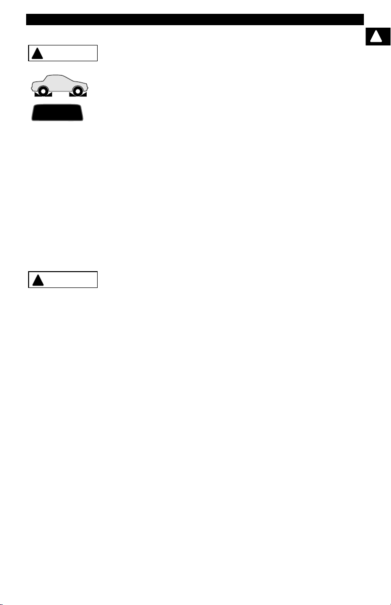
Risk of unexpected vehicle movement.
!
• Block drive wheels before performing a test with
engine running.
• Unless instructed otherwise:
- set parking brake
- put gear selector in neutral for manual transmissions
- put gear selector in park for automatic transmissions
- disconnect release mechanism on the automatic
parking brake release for testing and reconnect when
testing is completed.
• Do not leave a running engine unattended.
A moving vehicle can cause injury.
Risk of equipment or circuit damage.
• Unless specifically directed by manufacturer, make
sure ignition is off before connecting or
disconnecting connectors or any vehicle electrical
terminals.
• Do not create a short between battery terminals with
a jumper wire or tools.
Improper equipment use can cause equipment or circuit
damage.
• • • • • • • • • • • • • • • • • • • • • • • • • • • • • • • • • • • • • • • • • • • • • • • • • • • • • Safety – ix
Page 16
Safety Precautions
!
!
CAUTION
DANGER
!
Misdiagnosis may lead to incorrect or improper repair
and/or adjustment.
• Do not rely on erratic, questionable, or obviously
erroneous test information or results.
- If test information or results are erratic, questionable,
or obviously erroneous, make sure all connections
and data entry information are correct and test
procedures were performed correctly.
- If test information or results are still suspicious, do
not use them for diagnosis.
Improper repair and/or adjustment may cause vehicle or
equipment damage or unsafe operation.
Some vehicles are equipped with air bags.
• Follow service manual warnings when working
around air bag components or wiring.
- If service manual instructions are not followed, an air
bag may deploy unexpectedly, resulting in injury.
- Note an air bag can still deploy several minutes after
ignition key is off (or even if vehicle battery is
disconnected) because of a special energy reserve
module.
An air bag opening can cause injury.
Safety – x • • • • • • • • • • • • • • • • • • • • • • • • • • • • • • • • • • • • • • • • • • • • • • • • • • • • •
Page 17

Section 1 – Using This Manual
This manual contains instructions for the use and setup of your Scan Tool. A
table of contents and glossary are provided to make this manual easy to use.
Some of the information shown in text or illustrations is obtained using optional
equipment. A Sales Representative can determine option availability.
This section contains a list of conventions used.
Safety Messages
Refer to Safety Precautions on page Safety - i.
Check Note
A check note provides additional information about the subject in the preceding
paragraph.
Example:
✓ English is the default measurement unit.
Equipment Tips and Lists
Equipment tips and lists provide information that applies to specific equipment.
Each tip is introduced by this icon
Example:
❒ Observe all vehicle and/or equipment manufacturer’s cautions and
warnings when testing with the Scan Tool.
r for easy identification.
1
Equipment Damage
Situations arise during testing that could damage the vehicle or the test
equipment. The word IMPORTANT signals these situations.
Example:
IMPORTANT
• • • • • • • • • • • • • • • • • • • • • • • • • • • • • • • • • • • • • • • • • • • • • • • • • • • • • • • • • 1 – 1
Failure to follow these instructions could damage the Scan Tool.
Page 18

Using This Manual
Functions and Selections
Diagnostic and tool functions performed by the Scan Tool are highlighted in
bold.
Example:
The View Data function allows you to view the vehicle’s parameter identification
(PID) data in real time.
1
Menus
The menus on the Scan Tool display are referenced in the procedures and are
highlighted in bold-italic text.
Example:
When the OBDII Function List menu displays, the Scan Tool is ready for use.
Questions and Responses
Messages and user responses are CAPITALIZED.
Example:
The Scan Tool displays the pending DTCs or a message stating SYSTEM
PASS: NO FAULT DETECTED.
Manual References
Used to reference other sections of the manual. References include the Title
and page number (section-page).
Example:
For more information on DTCs, refer to “OBD II Diagnostic Trouble Codes
(DTCs)” on page 2-15
Screens
Certain help messages, information, and data that are displayed on the scan
tool are also shown in graphical text boxes. The screens are presented as
examples and may change as the software is updated.
Example:
Main Menu
Global OBD II
Domestic Vehicles
European Vehicles
Asian Vehicles
Review Data
Print Data
System Setup
1 – 2 • • • • • • • • • • • • • • • • • • • • • • • • • • • • • • • • • • • • • • • • • • • • • • • • • • • • • • • •
Page 19

Section 2 – Getting Started
Introduction
The Scan Tool was developed by experts in the automotive service
industry to help diagnose vehicles and assist in troubleshooting
procedures.
The Scan Tool monitors vehicle events and retrieves codes from the
vehicle’s control modules to help pinpoint problem areas.
All information, illustrations and specifications contained in this manual
are based on the latest information available from industry sources at
the time of publication.
No warranty (expressed or implied) can be made for its accuracy or
completeness, nor is any responsibility assumed by the manufacturer
or anyone connected with it for loss or damages suffered through
reliance on any information contained in this manual or misuse of
2
• • • • • • • • • • • • • • • • • • • • • • • • • • • • • • • • • • • • • • • • • • • • • • • • • • • • • • • • • 2 – 1
Page 20

Getting Started
accompanying product. The manufacturer reserves the right to make
changes at any time to this manual or accompanying product without
obligation to notify any person or organization of such changes.
Using the CD
✓ The included CD is NOT required to operate the Scan Tool
✓ Install the CD application prior to connecting the Scan Tool to the
PC.
2
✓ Some of the items included on the CD are:
❒ Manuals included with Scan Tool
❒ DTC lookup software
❒ Scan Tool update software
❒ Adobe Acrobat Reader Installer
❒ Print Capture
❒ Other product information
✓ To be able to use the included CD the PC must meet the following
minimum requirements:
❒ 486 PC
❒ 4 MB of RAM
❒ Microsoft Windows 98 SE, ME, 2000, and XP
❒ CD ROM Drive
❒ Adobe Acrobat Reader
2 – 2 • • • • • • • • • • • • • • • • • • • • • • • • • • • • • • • • • • • • • • • • • • • • • • • • • • • • • • • •
Page 21
Getting Started
❒ Internet Explorer 4.0 or newer
❒ Screen Resolution of 800 x 600
– If screen resolution is 800 x 600, in Display Properties, Settings
Tab, set Font Size to Small Fonts.
Installing Applications On Included CD
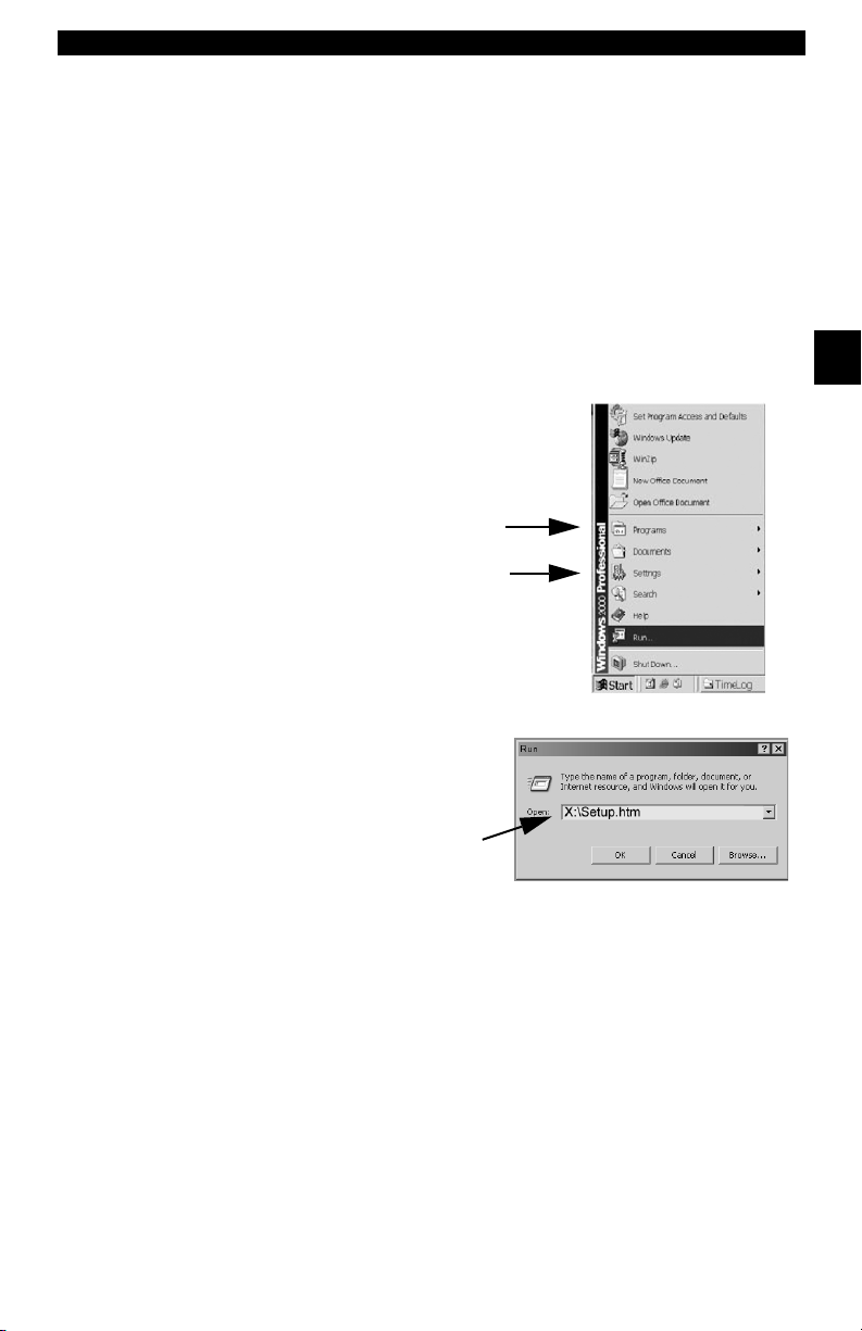
1. Close all programs on the computer.
2. Place the CD in CD-Drive.
✓ If CD does not start automatically;
❒ Select the Start button.
❒ Select Run...
❒ Enter “X:\Setup.htm” in Open Box on
Computer and select OK.
Run
Start
2
❒ “X” is the CD-ROM
drive letter on the
computer.
Enter
3. Follow screen prompts on the computer to install the
applications.
• • • • • • • • • • • • • • • • • • • • • • • • • • • • • • • • • • • • • • • • • • • • • • • • • • • • • • • • • 2 – 3
Page 22

Getting Started
Vehicle Service Information
The following is a list of web sites and phone numbers where electronic
engine control (EEC) diagnostic information is available.
✓ Some manuals may be available at your local dealer, auto parts
stores or local public libraries.
Domestic Vehicles Web Site Phone Number
General Motors
Chevrolet www.chevrolet.com 1-800-551-4123
2
Pontiac www.pontiac.com 1-800-551-4123
Oldsmobile www.oldsmobile.com 1-800-551-4123
Buick www.buick.com 1-800-551-4123
Cadillac www.cadillac.com 1-800-333-4CAD
Saturn www.saturn.com 1-800-553-6000
Ford
Ford www.ford.com 1-800-392-3673
Lincoln www.lincoln.com 1-800-392-3673
Mercury www.mercury.com 1-800-392-3673
Chrysler
Chrysler www.chrysler.com 1-800-348-4696
Dodge www.dodge.com 1-800-348-4696
Plymouth Not Available 1-800-348-4696
Eagle Not Available 1-800-348-4696
European Vehicles
Audi www.audi.com 1-800-544-8021
Volkswagon www.vw.com 1-800-544-8021
BMW www.bmw.com 1-201-307-4000
MINI www.mini.com 1-201-307-4000
Jaguar www.jaguar.com 1-800-4-JAGUAR
Volvo www.volvo.com 1-800-458-1552
Mercedes-Benz www.mercedes-benz.com 1-800-367-6372
Land Rover www.landrover.com 1-800-637-6837
Porsche www.porsche.com 1-800-PORSCHE
Saab www.saab.com 1-800-955-9007
Asian Vehicles Web Site Phone Number
Acura www.acura.com 1-800-999-1009
Honda www.honda.com 1-800-999-1009
Lexus www.lexus.com 1-800-255-3987
Scion www.scion.com 1.866.70.SCION
Toyota www.toyota.com 1-800-GO-TOYOTA
2 – 4 • • • • • • • • • • • • • • • • • • • • • • • • • • • • • • • • • • • • • • • • • • • • • • • • • • • • • • • •
Page 23

Getting Started
Hyundai www.hyundai.com 1-800-633-5151
Infiniti www.infiniti.com 1-800-662-6200
Nissan www.nissanusa.com 1-800-nissan1
Kia www.kia.com 1-800-333-4542
Mazda www.mazda.com 1-800-222-5500
Daewoo www.daewoo.com 1-822-759-2114
Subaru www.subaru.com 1-800-SUBARU3
Isuzu www.isuzu.com 1-800-255-6727
Geo Not Available Not Available
Mitsubishi www.mitsubishi.com 1-888-MITSU2004
Suzuki www.suzukiauto.com 1-800-934-0934
Other Manuals
Chilton Book Company www.chiltonsonline.com 1-800-347-7707
Haynes Publications www.haynes.com 1-800-242-4637
Bentley Publishers www.bentleypublishers.com 1-800-423-4595
Repair Information Programs
Mitchell www.mitchell1.com 1-888-724-6742
ALLDATA www.alldata.com 1-800-697-2533
Suitable Manual Titles
Diagnostic Service Manuals
PowerTrain Codes and Oxygen Sensors
Automotive Emission Control Manual
Fuel Injection
Automotive Electrical Manual
Automotive Electrics and Electronics
Automotive Sensors
Electronic Transmission Control
Emission Control Technology
Engine Management
or similar titles...
2
• • • • • • • • • • • • • • • • • • • • • • • • • • • • • • • • • • • • • • • • • • • • • • • • • • • • • • • • • 2 – 5
Page 24

Getting Started
Introduction to On-Board Diagnostics
OBD I
The original on-board diagnostics (OBD I) lacked consistency in
communication and interface while allowing different interpretations
among vehicle manufacturers. Ford and Chrysler used different types
of engine control computers and data link connectors ( DLCs), and GM
varied the trouble codes and communication protocols from
year-to-year.
OBD II
2
On-board diagnostics version II (OBD II) is a system that the Society of
Automotive Engineers (SAE) developed to standardize automotive
electronic diagnosis.
Beginning in 1996, most new vehicles sold in the United States were
fully OBD II compliant.
✓ Technicians can now use the same tool to test any OBD II
compliant vehicle without special adapters. SAE established
guidelines that provide:
❒ A universal connector, called the DLC, with dedicated pin
assignments.
❒ A standard location for the DLC, visible under the dash on driver’s
side.
❒ A standard list of diagnostic trouble codes (DTCs) used by all
manufacturers.
❒ A standard list of parameter identification (PID) data used by all
manufacturers.
❒ Ability for vehicle systems to record operating conditions when a
fault occurs.
❒ Expanded diagnostic capabilities that records a code whenever a
condition occurs that affects vehicle emissions.
❒ Ability to clear stored codes from the vehicle’s memory with a
Scan Tool.
2 – 6 • • • • • • • • • • • • • • • • • • • • • • • • • • • • • • • • • • • • • • • • • • • • • • • • • • • • • • • •
Page 25

Getting Started
SAE Publications
SAE has published hundreds of pages of text defining a standard
communication protocol that establishes hardware, software, and
circuit parameters of OBD II systems. Unfortunately, vehicle
manufacturers have different interpretations of this standard
communications protocol. As a result, the generic OBD II
communications scheme varies, depending on the vehicle. SAE
publishes recommendations, not laws, but the Environmental
Protection Agency (EPA) and California Air Resources Board (CARB)
made many of SAE’s recommendations legal requirements that vehicle
manufacturers were required to phase in over a three-year period.
Beginning in 1994, vehicles with a new engine management computer
( about 10% of each manufacturers fleet ) were supposed to comply
with OBD II standards. For 1995, OBD II systems were to appear on
about 40% of the new vehicles sold in the United States. Some of the
1994-1995 OBD II systems were not fully compliant, so the Government
granted waivers to give manufacturers time to fine-tune their systems.
Beginning in 1996, most of the new vehicles sold in the United States
were fully OBD II compliant.
The tables below highlight changes for GM, Ford, and Chrysler. If this
seems confusing, don’t worry. The Scan Tool makes it easy. Based on
the vehicle identification (VIN) information selected during Scan Tool
setup, the vehicle is automatically recognized. All you have to do is
choose the correct adapter cable and jumper wires (if necessary).
Details on adapter cables and jumper wires may be found in Data LInk
Connector on page 2-9.
2
GM On-Board Diagnostics
System Years Description
Most vehicles used the 12-pin ALDL (Assembly Line Data Link)
OBD I Control Module
OBD II Control Module
*
OBD II system is used on certain 1994-1995 vehicles equipped with a 2.2L, 2.3L, 3.8L, 4.3L or 5.7L
engines.
• • • • • • • • • • • • • • • • • • • • • • • • • • • • • • • • • • • • • • • • • • • • • • • • • • • • • • • • • 2 – 7
1981–1995
1994*-Present Complies with OBD II regulations and uses the J1962 DLC.
located under the dash on the driver side. Some 94-95 vehicles
used the 16-pin OBD II (J1962) data link connector (DLC), but
use the Historical application software. Refer to the vehicle’s
Vehicle Emission Control Information label.
Page 26

Getting Started
Ford On-Board Diagnostics
System Long Name Years Description
MCU
Microprocessor Control Unit 1980 –1991
EEC-IV
2
* EEC-V OBD II system used in 1994-1995 vehicles equipped with a 3.8L or 4.6L engine.
Electronic Engine Control,
Fourth generation
Mazda Electronic Control
MECS
System
Electronic Engine Control,
EEC-V
Fifth generation
Powertrain Electronic
PTEC
Controller
1984 –1995
1988 –1995
1994* – present
2000 – present
Used in police vehicles, containing carbureted
engines. Uses the MCU DLC.
Most Ford vehicles equipped with North
American engines. Uses the EEC-IV DLC.
Vehicles equipped with Mazda-sourced engines.
Uses MECS 6-pin and 17-pin DLCs.
Complies with OBD II regulations and uses the
OBD II J1962 DLC.
Complies with OBD II regulations and uses the
OBD II J1962 DLC.
Chrysler On-Board Diagnostics
System Long Name Years Description
Single Module Engine
SMEC
Controller
Single Board Engine
SBEC
Controller
OBD II
OBD II Powertrain
PCM
Control Module
Jeep/Truck Engine
JTEC
Controller
* In 1989, the SBEC system was installed in selected vehicles with 3.0L V6 engines.
** Some vehicles in 1995 were equipped with the OBD II PCM.
1989–1990
1989*–1995
1995**– present
1996– present
Used a 6-pin Serial Communication Interface (SCI)
DLC and has bidirectional capability.
Used two types of DLCs: a 6-pin SCI and a 6-pin LH
series.
The first to allow a tool to reset the EMR light on trucks.
Complies with OBD II regulations and uses the OBD II
J1962 DLC.
Complies with OBD II regulations and uses the OBD II
J1962 DLC.
The JTEC system is used on light-duty trucks and
Jeeps
2 – 8 • • • • • • • • • • • • • • • • • • • • • • • • • • • • • • • • • • • • • • • • • • • • • • • • • • • • • • • •
Page 27
Getting Started
Data Link Connector (DLC)
The data link connector (DLC) allows the Scan Tool to communicate
with the vehicle’s computer(s). Before OBD II, manufacturers used
different DLC’s to communicate with the vehicle. use the proper DLC
adapter cable to connect the Scan Tool to the vehicle. Also, the vehicle’s
DLC may be found in several different places and have many different
configurations. The following describes the DLCs used by Ford, GM
and Chrysler. The DLC location and types for domestic vehicles can be
looked up in the charts in Appendix B - Data Link Connectors.
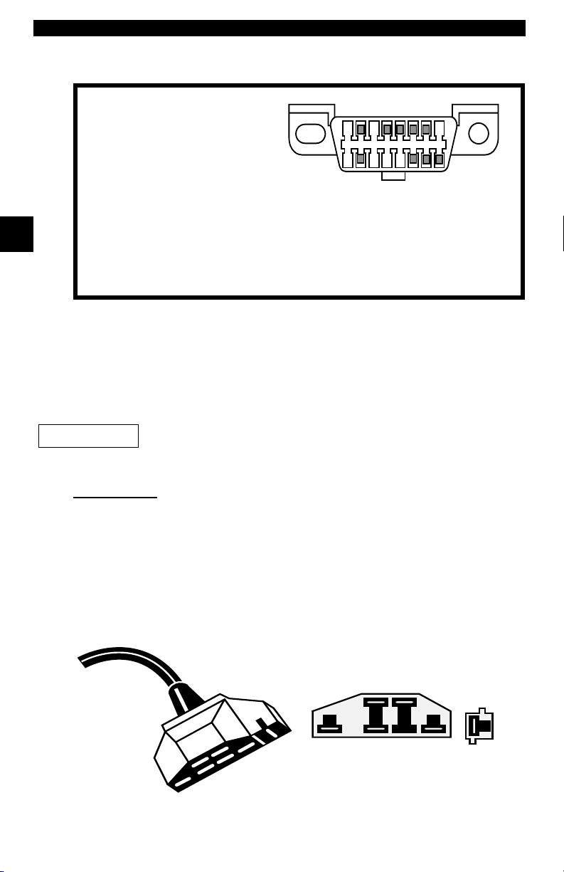
OBD II (J1962)
Beginning in 1996, vehicles sold in the United States use the J1962
(OBD II) DLC, a term taken from a physical and electrical specification
number assigned by the SAE (J1962). The DLC should be located
under the dashboard on the driver’s side of the vehicle. If the DLC is not
located under the dashboard as stated, a decal describing its location
should be attached to the dashboard in the area the DLC should have
been located.
Because the OBD II J1962 connector has power and ground, you only
need a single cable connection to the tool for both power and tool
communications. Attach the OBD II adapter cable to the extender cable,
(both supplied with the tool) to connect the tool. Certain pins in the
connector are reserved.
.
2
• • • • • • • • • • • • • • • • • • • • • • • • • • • • • • • • • • • • • • • • • • • • • • • • • • • • • • • • • 2 – 9
Page 28
Getting Started
Data Link Connector (DLC) Pins
2
Ford Historic
IMPORTANT
EEC-IV/MCU
1 - Manufacturer Reserved
2 - J1850 Bus+
3 - Manufacturer Reserved
4 - Chassis Ground
5 - Signal Ground
6 - CAN High, J-2284
7 - K Line, ISO 9141-2 & ISO/DIS 14230-4
8 - Manufacturer Reserved
9 - Manufacturer Reserved
10 - J1850 Bus11 - Manufacturer Reserved
12 - Manufacturer Reserved
1
9
13 - Manufacturer Reserved
14 - CAN Low, J-2284
15 - L Line, ISO 9141-2 & ISO/DIS 14230-4
16 - Battery Power
8
16
Ford used three types of DLCs with their OBD I systems. Refer to
Appendix B - Data Link Connectors for the adapter cable needed for
your vehicle.
Use the cigarette lighter cable to provide power to the
Scan Tool for all systems.
The EEC-IV/MCU DLC is a large six-sided connector with a pigtail
connector. The pigtail connector is not used on MCU vehicles – leave
the pigtail unattached. The EEC-IV/MCU cable adapter is included with
the Scan Tool.
Cable Adapter
EEC-IV/MCU
To Scan
Tool
Vehicle DLC
EEC-IV/MCU
STI Pigtail
EEC-IV
only
2 – 10 • • • • • • • • • • • • • • • • • • • • • • • • • • • • • • • • • • • • • • • • • • • • • • • • • • • • • • •
Page 29
Getting Started
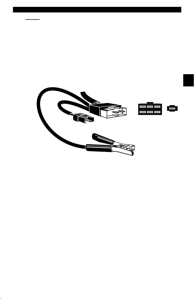
MECS
MECS vehicles (1988 –1995) use either a 6-pin (with pigtail) or a 17-pin
DLC. Use the MECS 6-pin adapter cable kit (CP9131) for both
configurations. The MECS adapter cable kit includes jumper wires to
connect to the MECS 17-pin DLC. The MECS adapter cable kit is
optional and must be purchased separately. Use the following diagrams
to connect the adapter cable.
6-Pin MECS
Cable Adapter
6-Pin MECS
P/N CP9131
To Scan
Too l
STI Pigtail
Vehicle DLC
6-Pin MECS
2
Pigtail
6
5
4
3
2
1
Clip to good
vehicle ground
• • • • • • • • • • • • • • • • • • • • • • • • • • • • • • • • • • • • • • • • • • • • • • • • • • • • • • • • 2 – 11
Page 30
Getting Started
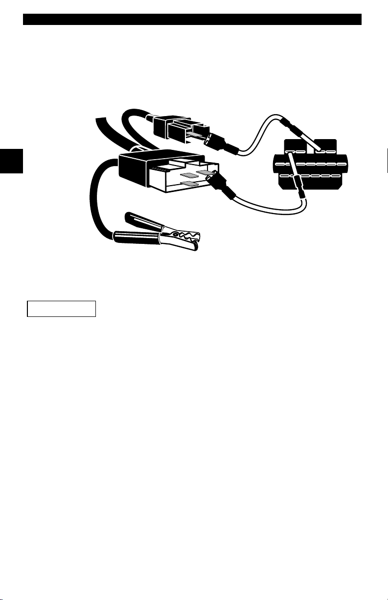
17-Pin MECS
2
IMPORTANT
Adapter Cable
To
Scan Tool
MECS Ford Probe
Certain Ford Probes have a WHITE TACH
CONNECTOR located very close to the 6-pin
self-test connector and bundled in the same wiring
harness. This is not the self-test input (STI) pigtail.
6-Pin MECS
P/N CP9131
4
1
STI Pigtail
6
5
3
2
Clip to good
vehicle ground
Vehicle DLC
17-Pin MECS
STO
Connect the pigtail to the BLACK STI connector located farther back on
the wire harness. If the tool is connected to the WHITE tach connector,
serious damage may result and may void warranty. Refer to the
illustration.
2 – 12 • • • • • • • • • • • • • • • • • • • • • • • • • • • • • • • • • • • • • • • • • • • • • • • • • • • • • • •
Page 31

Getting Started
GM Historic
Prior to1996, most GM vehicles used the 12-pin Assembly Line
Diagnostic Link (ALDL) DLC. The GM ALDL cable kit includes the ALDL
adapter and cigarette lighter power cable. This adapter cable is
included with the Scan Tool. In 1994 and 1995, certain GM vehicles
used the J1962 (OBD II) DLC, but are not OBD II compliant. Refer to
Appendix B - Data Link Connectors.
IMPORTANT
The ALDL DLCs are usually located
under the dashboard on the driver’s
side.
On Corvettes and Fieros, the DLC may
be located in the center console behind
the ashtray. Refer to service manual
for exact location. It may be in full view,
or it may be recessed behind a panel. An opening in the panel should
allow access to the recessed connector.
Use the cigarette lighter cable to provide 12V to the
tool
.
ALDL
FGEHDJCKBLA
M
2
• • • • • • • • • • • • • • • • • • • • • • • • • • • • • • • • • • • • • • • • • • • • • • • • • • • • • • • • 2 – 13
Page 32

Getting Started
Chrysler Historic
Prior to 1996, most Chrysler vehicles used either the serial
communications interface (SCI) or LH DLC. Refer to Appendix B -
Data Link Connectors for DLC type and location. The SCI adapter
cable is included with the Scan Tool. The LH adapter cable (CP9130)
can be purchased from your dealer.
IMPORTANT
2
Serial Communications Interface SCI
LH
Use the cigarette lighter cable to provide 12V to the tool
when using the SCI adapter cable.
SCI
The SCI (serial communications interface) DLC
is a 6-pin connector located in the engine
compartment. The adapter cable to be used on
these vehicles is supplied with the tool. This
cable is labeled CHRY on the 15-pin DB style
connector and SCI on the vehicle end.
LH (P/N CP9130)
This DLC is used on LH platform vehicles. The
LH style DLC is a small, blue, rectangular 6-pin
connector located in the passenger
compartment below the dashboard to the right of
the steering column.
The LH Adapter Cable (CP9130) is optional and
must be purchased separately.
2 – 14 • • • • • • • • • • • • • • • • • • • • • • • • • • • • • • • • • • • • • • • • • • • • • • • • • • • • • • •
Page 33

Getting Started
OBD II Diagnostic Trouble Codes
(DTCs)
✓ DTCs are used to help determine the cause of a problem or
problems with a vehicle.
❒ DTCs consist of a five-digit alphanumeric code.
❒ The DTCs format and general code types are shown bel
Bx - Body
Cx - Chassis
Px - Powertrain
Ux - Network Comm.
x = 0, 1, 2 or 3
Example:
P0101 - Mass or Volume Air Flow Circuit Range/Performance Problem
Powertrain Codes
P0xxx - Generic (SAE)
P1xxx - Manufacturer Specific
P2xxx - Generic (SAE)
P30xx-P33xx - Manufacturer Specific
P34xx-P39xx - Generic (SAE)
Chassis Codes
C0xxx - Generic (SAE)
C1xxx - Manufacturer Specific
C2xxx - Manufacturer Specific
C3xxx - Generic (SAE)
P 0 1 0 1
Body Codes
B0xxx - Generic (SAE)
B1xxx - Manufacturer Specific
B2xxx - Manufacturer Specific
B3xxx - Generic (SAE)
Network Communication Codes
U0xxx - Generic (SAE)
U1xxx - Manufacturer Specific
U2xxx - Manufacturer Specific
U3xxx - Generic (SAE)
Specific Fault Designation
Vehicle Specific System
Within each category (Powertrain, Chassis, Body and Network) of
DTCs there are assigned ranges for different vehicle systems.
2
• • • • • • • • • • • • • • • • • • • • • • • • • • • • • • • • • • • • • • • • • • • • • • • • • • • • • • • • 2 – 15
Page 34

Getting Started
L
Assi
d DTC Syst
owerUpper
P0000 P00FF
P0100 P02FF
P0300 P03FF
P0400 P04FF
P0500 P05FF
P0600 P06FF
P0700 P09FF
P0A00 P0AFF
2
P1000 P10FF
P1100 P12FF
P1300 P13FF
P1400 P14FF
P1500 P15FF
gne
Fuel Air Metering Auxiliary
Emission Controls
Fuel Air Metering
Ignition System or Misfire
Auxiliary Emission Controls
Vehicle Speed Idle Control
Auxiliary Inputs
Computer and Auxiliary
Outputs
Transmission
Hybrid Propulsion
Manufacturer Control Fuel &
Air Metering, Auxiliary
Emission Controls
Manufacturer Control Fuel &
Air Metering
Manufacturer Control Ignition
System or Misfire
Manufacturer Control
Auxiliary emission Controls
Manufacturer Cntrl Veh.Spd.
Idle Speed Control Auxiliary
Inputs
em
Lower Upper Assigned DTC System
P1600 P16FF
P1700 P19FF
P2000 P22FF
P2300 P23FF
P2400 P24FF
P2500 P25FF
P2600 P26FF
P2700 P27FF
P2900 P32FF
P3300 P33FF
P3400 P34FF
U0000 U00FF
U0100 U02FF
U0300 U03FF
U0400 U04FF
Manufacturer Control
Auxiliary Inputs Auxiliary
Outputs
Manufacturer Control
Transmission
Fuel Air Metering Auxiliary
emission Controls
Ignition System or Misfire
Auxiliary Emission Controls
Auxiliary Inputs
Computer and Auxiliary
Outputs
Transmission
Fuel Air Metering Auxiliary
Emission Controls
Ignition System
Cylinder Deactivation
Network Electrical
Network Communication
Network Software
Network Data
✓ J2012 and ISO 15031-6 are standards for all DTCs, established by
the SAE, International Organization for Standardization (ISO) and
other governing bodies.
❒ Codes and definitions assigned by these specifications are
known as Generic OBD II codes.
❒ OBD II requires compliance to these standards for all cars, light
trucks, APVs, MPVs, and SUVs sold in the United States.
❒ Codes not reserved by the SAE are reserved for the
manufacturer and referred to as Manufacturer Specific Codes.
2 – 16 • • • • • • • • • • • • • • • • • • • • • • • • • • • • • • • • • • • • • • • • • • • • • • • • • • • • • • •
Page 35

Section 3 – Using The Scan Tool
The Scan Tool
1 LCD Display – backlit, 128 x 64 pixel display with contrast adjustment.
2
UP
and DOWN
3 ENTER key – selects displayed items.
4 LEFT and RIGHT arrow keys – selects YES or NO, and selects data
parameters for custom data list.
5 BACK key – goes to the previous screen or level.
6
7
8 USER key - allows the operator to access a feature from the Diagnostic
9 DLC Cable – provides connection for vehicle interface.
10
11
12
13
ON/OFF
HELP
Menu with a touch of a key.
USB Port – provides a USB connection for the computer.
12V Power Jack– provides power to the Scan Tool when reprogramming
from a personal computer, communicating with Ford, GM and Chrysler
Historic vehicles, or off-vehicle reviewing of codes and printing.
Serial Number Plate – provides serial number of Scan Tool.
Battery Compartment – provides power to the Scan Tool when
reprogramming from a personal computer or off-vehicle reviewing of codes
and printing.
key – turns power ON or OFF.
key – accesses the Help Function.
arrow keys – moves selection UP or DOWN.
Top of Scan Tool
3
1
2
7
3
10
Back of Scan Tool
11
9
12
4
8
6
4
5
2
13
• • • • • • • • • • • • • • • • • • • • • • • • • • • • • • • • • • • • • • • • • • • • • • • • • • • • • • • • • 3 – 1
Page 36

Using The Scan Tool
Specifications
Display: Backlit, 128 x 64 pixel display with contrast adjust
Operating Temperature: 0 to 50°C (32 to 122°F)
Storage Temperature: -20 to 70°C (-4 to 158°F)
Internal Power: 9V Battery
External Power: 7 to 16 Volts
✓ A minimum of 8.0 V is required for most control modules to operate
properly in a vehicle.
3
Power Dissipation: 5 Watts maximum.
Dimensions: Height
1.25" 3.875" 9.125"
31.75 mm 98.4 mm 231.8 mm
Width Length
3 – 2 • • • • • • • • • • • • • • • • • • • • • • • • • • • • • • • • • • • • • • • • • • • • • • • • • • • • • • • •
Page 37

Using The Scan Tool
Accessories for the Scan Tool
Table 1: Scan Tool Accessories
Part Part Description CP9185 CP9190
CD The CD contains the Manual in English,
French and Spanish. The CD also includes a
DTC lookup program for looking up DTCs,
and language applications for reprogramming the Scan Tool in Spanish and French.
USB Cable Used to print and upgrade software depend-
ing on tool.
OBD II Cable Communicate between the vehicle and tool.
Also supplies power to the tool.
Carry Case Place to store the Scan Tool when tool is
not in use.
Warrant y &
Registration
Card
GM Historic
Cable
Ford
EEC-IV/MC
U Cable
Chrysler SCI
Cable
Provides you with the ability to keep up to
date with the newest updates and technology available.
Used to communicate with all GM vehicles
using a 12-pin DLC.
Used to communicate with all Ford vehicles
that use the large 6-sided connector.
Used to communicate with all Chrysler
vehicles using the L-shaped 6-pin connector located in the engine compartment.
Included Included
Included Included
Included Included
Soft Case Hard Case
Included Included
Optional Included
Optional Included
Optional Included
3
Extension
Cable
Cigarette
Lighter Cable
• • • • • • • • • • • • • • • • • • • • • • • • • • • • • • • • • • • • • • • • • • • • • • • • • • • • • • • • • 3 – 3
Used to attach the GM Historic cable, Ford
EEC- IV/MCU cable or Chrysler SCI cable
to the Scan Tool.
Provides power to the Scan Tool for vehicles that require the Ford EEC-IV/MCU
cable, GM Historic cable or Chrysler SCI
cable.
Included Included
Optional Included
Page 38

Using The Scan Tool
✓ Replacement Parts are available from the manufacturer by
contacting customer service.
• Phone at 1-800-228-7667 (8:00 - 6:00 EST Monday - Friday).
Display
The display has a large viewing area displaying messages, instructions,
and diagnostic information.
✓ The back-lit liquid crystal display (LCD) is a 128 x 64 pixel display.
❒ Characters used to help operate the Scan Tool are:
3
[
Indicates cursor location.
Indicates information is available for an item or multiple items.
Indicates when Help is available.
\ Indicates additional information is available on previous screen
by using the
]
Indicates additional information is available on next screen by
using
the DOWN
UP
arrow key.
arrow key.
Indicates internal batteries need replaced or are not installed.
Indicates beeper is enabled.
Indicates graphical viewing available.
Global OBD II
Domestic Vehicles
European Vehicles
Asian Vehicles
Review Data
Print Data
System Setup
?
Main Menu
Global OBD II
Keypad
The keypad is used to move through the different menus of the Scan
Tool. The Scan Tool’s software is designed for ease in operating and
navigating through menus.
!
CAUTION
3 – 4 • • • • • • • • • • • • • • • • • • • • • • • • • • • • • • • • • • • • • • • • • • • • • • • • • • • • • • • •
Do not use solvents such as alcohol to clean keypad
or display. Use a mild nonabrasive detergent and a
soft cotton cloth.
Page 39

Using The Scan Tool
!
CAUTION
Do not soak keypad as water might find its way
inside the Scan Tool.
Power
✓ Refer to Scan Tool Does Not Power Up in section 9
Troubleshooting on page 9-2 if there are problems.
✓
Internal Battery
ON/OFF
on and off.
❒ Press and hold
least 1 second to turn on Scan Tool.
button on Scan Tool turns tool
ON/OFF
key for at
✓ When powered from the internal battery,
the Scan Tool disables the display’s
backlighting and turns OFF after a period of inactivity.
3
• • • • • • • • • • • • • • • • • • • • • • • • • • • • • • • • • • • • • • • • • • • • • • • • • • • • • • • • • 3 – 5
Page 40

Using The Scan Tool
Diagnostic
Connector
✓ Each time the Scan Tool is
powered up, voltage of the internal
battery is checked.
❒ If voltage is low, the Low
Battery Symbol ( ) displays
on screen.
❒ Replace the battery using
instructions provided in Battery
Replacement.
Main Menu
Global OBD II
Global OBD II
Domestic Vehicles
European Vehicles
Asian Vehicles
Review Data
Print Data
System Setup
3
!
CAUTION
If the Scan Tool will not be used for an extended
period of time, remove the battery to prevent battery
leakage from damaging the battery compartment.
Vehicle Power
When using the OBD II Cable, the power to
the Scan Tool comes from the vehicle DLC.
Some vehicle cigarette lighters are not
powered when the ignition is in the OFF
position. Therefore, you may wish to use
battery clip adapters.
3 – 6 • • • • • • • • • • • • • • • • • • • • • • • • • • • • • • • • • • • • • • • • • • • • • • • • • • • • • • • •
Page 41

Using The Scan Tool
AC Power Adapter
An AC power adapter (not included) can be used to power the Scan Tool
when reprogramming from a personal computer or for off-vehicle
reviewing of codes and printing.12V AC-DC converters are available at
most PC and electronic stores.
✓ The Scan Tool is equipped to accept any
110 VAC - 12 VDC wall adapter with the
following specifications:
❒ 500 mA minimum current unregulated wall power adapter
❒ 5.5 mm outside diameter
❒ 2.5 mm inside diameter
❒ The inside tip is positive (+)
Scan Tool Power UP
1. Connect Power Source
•
Internal Battery
• AC Adapter, or cigarette lighter cable.
(9V Battery), or vehicle Power DLC
12 VGND
3
ON/OFF
2. Press and Hold
•
For 1 second until the Scan Tool turns on.
key
System Setup
✓ System Setup allows:
❒ Measurement units to be changed.
❒ Display contrast to be changed.
❒ Auto-Power off time to be changed.
❒ Scan Tool information to be viewed.
❒ Display to be checked.
❒ Operation of the keypad to be checked.
❒ Memory of the tool to be checked.
❒ Scan Tool to be upgraded, or programmed for a different
language.
• • • • • • • • • • • • • • • • • • • • • • • • • • • • • • • • • • • • • • • • • • • • • • • • • • • • • • • • • 3 – 7
Page 42

Using The Scan Tool
English/Metric
Contrast Adjust
Be eper
Auto Power Off
Tool Information
Display Test
Keyboard Test
System Setup
English/Metric
✓ System Setup settings remain until internal battery becomes
discharged or is removed.
From Main Menu:
1.Select System Setup.
•Use
UP
or DOWN
key until System Setup is
highlighted.
•Press
ENTER.
3
Changing Measurement Units
✓ English is the default measurement unit.
✓ Measurement units can be changed in View and Record Data.
arrow
Main Menu
Global OBD II
Domestic Vehicles
European Vehicles
Asian Vehicles
Review Data
Print Data
System Setup
System Setup
?
From System Setup screen:
1.Select English/Metric.
•Use
UP
or DOWN
arrow
key until English/Metric is
highlighted.
•Press
3 – 8 • • • • • • • • • • • • • • • • • • • • • • • • • • • • • • • • • • • • • • • • • • • • • • • • • • • • • • • •
ENTER.
Page 43

Using The Scan Tool
2.Select Desired
Measurement Unit.
•Use
UP
or DOWN
key until desired unit is
highlighted.
3.Save Measurement Setting.
•Press
ENTER.
✓ Press ENTER again to return to the
System Setup menu.
arrow
Measurement Units
English (Default)
English/Metric
Metric
3
Changing Display Contrast
From System Setup screen:
1.Select Contrast Adjust.
•Use
key until Display Contrast is
highlighted.
•Press
• • • • • • • • • • • • • • • • • • • • • • • • • • • • • • • • • • • • • • • • • • • • • • • • • • • • • • • • • 3 – 9
UP
or DOWN
ENTER.
arrow
System Setup
English/Metric
Contrast Adjust
Display Contrast
Be eper
Auto Power Off
Tool Information
Display Test
Keyboard Test
Page 44

Using The Scan Tool
2.Increase or Decrease
3.Save Contrast Setting
3
Display Contrast.
•Use
UP arrow key to
increase Contrast.
•Use
DOWN
arrow key to
decrease Contrast.
Adjust Contrast
50%
Darken
Lighten
Press ENTER
when done.
and return to the System
Setup menu.
•Press
ENTER.
Beeper
✓ Beeper selection allows the user to turn off the Scan Tool’s beeper.
The bell symbol
the display when the beeper is off.
From System Setup menu:
3 – 10 • • • • • • • • • • • • • • • • • • • • • • • • • • • • • • • • • • • • • • • • • • • • • • • • • • • • • • •
will not appear in the lower right hand corner of
Page 45

Using The Scan Tool
English/Metric ?
Contrast Adjust
Be eper
Auto Power Off
Tool Information
Display Test
Keyboard Test
System Setup
Be eper
English/Metric
Contrast Adjust
Be eper
Auto Power Off
Tool Information
Display Test
Keyboard Test
System Setup
Auto Power Off
1.Select Beeper.
• Use
UP
or DOWN
arrow
key until Beeper is highlighted.
• Press
ENTER.
2.Select desired Beeper sound
choice.
• Use
UP
or DOWN
key until desired choice is
arrow
Be eper Sound
On (Default)
English/Me
Off
highlighted.
3.Save Beeper sound setting.
• Press
ENTER.
✓ Press ENTER again to return to the System Setup menu.
3
Changing Auto-Power Off
The Auto-Power Off feature allows the tool to turn off automatically after
a selected amount of time when tool is not being used.
From System Setup menu:
1.Select Auto Power Off.
•Use
key until Auto Power Off is
highlighted.
•Press
• • • • • • • • • • • • • • • • • • • • • • • • • • • • • • • • • • • • • • • • • • • • • • • • • • • • • • • • 3 – 11
UP
or DOWN
ENTER.
arrow
Page 46

Using The Scan Tool
English/Metric
Contrast Adjust
Be eper
Auto Power Off
Tool Information
Display Test
Keyboard Test
System Setup
Tool Information
2.Increase or Decrease Auto
3.Save Auto Power Off Time.
3
✓ Press ENTER again to return to the
System Setup menu.
Power Off Time.
•Use
UP arrow key to
increase Time.
•Use
DOWN
arrow key to
decrease Time.
•Press
ENTER.
Auto Power Off
15
Minutes
Increase Time
Decrease Time
Press ENTER when done.
View Tool Information
✓ This function allows you to view specific tool information that may
be needed when contacting customer service.
From System Setup menu:
1.Select Tool Information.
•Use
key until Tool Information is
highlighted.
•Press
3 – 12 • • • • • • • • • • • • • • • • • • • • • • • • • • • • • • • • • • • • • • • • • • • • • • • • • • • • • • •
UP
or DOWN
ENTER.
arrow
Page 47

Using The Scan Tool
English/Metric
Contrast Adjust
Be eper
Auto Power Off
Tool Information
Display Test
Keyboard Test
System Setup
Display Test
2.View Information:
❒Serial Number (Serial No:)
❒Software ID (SW ID:)
❒Hardware Version
(HW Ver:)
❒Boot Version (Boot Ver:)
❒Product ID (Prod ID:)
❒Board ID (Board ID:)
❒Burn Date (Burn Date:)
❒Burn Location (Burn Loc:)
3.Write Down Scan Tool Information.
• Space is provided on inside front cover to record the Scan Tool
information.
4.Return to Setup Tool Menu.
•Use the
OR
•Use the
Tool Information
Serial No: 10002076
SW ID: 0A46H
HW Ver: 1
Boot Ver: 1
Prod ID: 5
Board ID: 11
Burn Date: 04/25/04
3
BACK key.
ENTER Key.
Display Test
The Display Test is used to check the display.
✓ The test fills every pixel of the display with a solid black character.
From System Setup menu:
1.Select Display Test.
•Use
key until Display Test is
highlighted.
• • • • • • • • • • • • • • • • • • • • • • • • • • • • • • • • • • • • • • • • • • • • • • • • • • • • • • • • 3 – 13
UP
or DOWN
arrow
Page 48

Using The Scan Tool
Check for missing
spots in the display
Press Back
to Quit
Display Test
2. Start Display Test.
3. Look for Missing Spots.
3
•Press
ENTER.
• All characters display in solid black if
there are no concerns.
• Screen flips back and forth between
screens shown below.
4. When Done, Press
BACK Key.
3 – 14 • • • • • • • • • • • • • • • • • • • • • • • • • • • • • • • • • • • • • • • • • • • • • • • • • • • • • • •
Page 49

Using The Scan Tool
English/Metric
Contrast Adjust
Be eper
Auto Power Off
Tool Information
Display Test
Keyboard test
System Setup
Keyboard Test
Keyboard Test
The Keyboard Test is used to verify keys are working correctly.
From System Setup menu:
1.Select Keyboard Test.
•Use
key until Keyboard Test is
highlighted.
•Press
2. Press a
• Key name or scroll direction should
inverse colors on display.
• The only exception is the
key. When
System Setup menu returns.
UP
or DOWN
ENTER.
KEY.
BACK key is pressed,
arrow
3
BACK
✓ If System Setup menu does not return,
then
correctly.
Memory Test
BACK key is not working
✓ The Memory Test will test RAM and Flash ROM.
✓ Run the Memory Test if the tool has trouble:
❒ Playing back recorded data.
❒ Displaying trouble code definitions.
❒ Doing any function that uses internal memory.
• • • • • • • • • • • • • • • • • • • • • • • • • • • • • • • • • • • • • • • • • • • • • • • • • • • • • • • • 3 – 15
Page 50

Using The Scan Tool
Contrast Adjust
Be eper
Auto Power Off
Tool Information
Display Test
Keyboard Test
Memory Test
System Setup
Memory Test
From System Setup menu:
1.Select Memory Test.
✓ Dots along the bottom of the
screen show progress of the
Memory Test.
❒ Memory Test may take
3
❒ Memory Test results display.
•Use
UP or DOWN
arrow
key until Memory Test is
highlighted.
•Press
several minutes to complete.
ENTER.
RAM Pass
ROM FAIL 1234
............
❒ If no problems were
detected, then PASS is displayed
❒ If RAM fails, an error message is shown.
❒ If ROM fails, a checksum is shown.
Memory Test
2. Return to System Setup menu.
•Press
3 – 16 • • • • • • • • • • • • • • • • • • • • • • • • • • • • • • • • • • • • • • • • • • • • • • • • • • • • • • •
ENTER.
Page 51

Using The Scan Tool
Program Mode
The Program Mode is used for
reprogramming the Scan Tool with
English, Spanish or French
languages. The Scan Tool is
programmed with English by
default.
The Program Mode is also used for
updating the Scan Tool. Instructions
are provided with upgrades.
System Setup
Be eper
Auto Power Off
Tool Information
Display Test
Keyboard Test
Memory Test
Program Mode
Program Mode
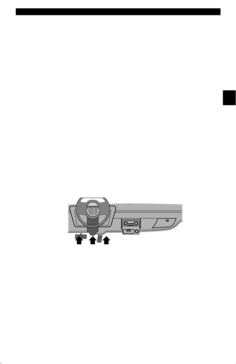
Connecting The Scan Tool
To diagnose a vehicle, connect the DLC and power adapter (if
applicable) to the Scan Tool. Refer to “Data Link Connector (DLC)” on
page 2-9 of Getting Started.
If you just want to power up the tool to do self-tests, code lookup, review
or printing data from the last vehicle tested, then you do not need to
attach the cable to the DLC. The internal battery provides power for this
1.Connect appropriate cable to Scan
Tool
•Make sure pins are not bent.
✓ Depending on vehicle, either the OBD II
Cable or Extension Cable is required.
3
.
• • • • • • • • • • • • • • • • • • • • • • • • • • • • • • • • • • • • • • • • • • • • • • • • • • • • • • • • 3 – 17
Page 52

Using The Scan Tool
Diagnostic
Connector
2.Find DLC on vehicle.
•For OBD II vehicles, look
under the dashboard on the
driver’s side of the vehicle.
•If the DLC is not located
under the dashboard, a
label should be there telling
the location.
For GM, Ford, and Chrysler Historic vehicles refer to “
Link Connectors
3
✓ Use the appropriate vehicle cable for
Review Data
✓ The Review Data function allows the user to view the information
✓ Scan Tool does not require power from the vehicle to use the
".
3.Remove DLC cover if required.
4.Connect cable to vehicle.
•Make sure pins are not bent.
vehicles that require the extension cable.
from the previous vehicle tested.
Review Data function.
1. Select Review Data.
•Use
or DOWN
arrow
UP
key until Review Data is
highlighted.
•Press
ENTER.
Appendix B - Data
Main Menu
Global OBD II
Domestic Vehicles
European Vehicles
Asian Vehicles
Review Data
Review Data
Print Data
System Setup
3 – 18 • • • • • • • • • • • • • • • • • • • • • • • • • • • • • • • • • • • • • • • • • • • • • • • • • • • • • • •
Page 53

Using The Scan Tool
I/M Readiness
Read Codes
Pending Codes
Fre eze Data
O2 Monitor Test
Diag Mon Test
Playback
Review Data
Read Codes
✓ Scan Tool Review Data function has different types of data to review
depending on vehicle selected.
Refer to appropriate section of this manual for what functions have data
for review.
2.Follow prompts and instructions provided by Scan Tool.
✓ The Review Data menu shows a
checkmark next to the item(s) that
has data.
✓ If data does not exist for function
selected to review, a message
informs the user to run a function
first.
✓ Only 1 function, Playback, needs detailed instructions.
Playback
The Playback function is used to playback a recording.
✓ This function is very similar to View Data. The only difference is that
View Data is real time viewing of PIDs, while Playback is a viewing
of previously recorded PIDs.
From the Review Data menu:
1.Select Playback.
•Use
key until Playback is
highlighted.
✓ Scan Tool displays a NO
RECORDING PRESENT
message if recording does not
exist.
• • • • • • • • • • • • • • • • • • • • • • • • • • • • • • • • • • • • • • • • • • • • • • • • • • • • • • • • 3 – 19
UP
or DOWN
arrow
Review Data
Fre eze Frame
State OBD Check
O2 Monitor Test
Diag Mon Tests
Playback
Playback
Vehicle Info
Modules Present
3
Page 54

Using The Scan Tool
ON
MIL STATUS
ABS TPS(%) 100
ENGINE (RPM) 688
A/F RATIO 14:1
CALC LOAD 83.1
FRAME:0 TM 0.0
100+
ABS TPS (%) 59%
0 +
FRAME:0 TM 0.0
2. Play Back Recording.
•Press
ENTER.
✓ On GM Historic and Ford Historic
vehicles, you must select the data to
playback as an Entire Data List or
Custom Data List.
3
✓ The Playback has frame number
and timestamp (in seconds).
❒ Negative frames and
timestamps indicate data
recorded before trigger event.
❒ Positive frames and
timestamps indicate data
recorded after trigger event.
❒ Use
UP
or DOWN
arrow
keys to view recorded PID data of each frame.
❒ Use LEFT or RIGHT arrow keys to scroll back and forth
through frames.
❒ If graphing is available for
selected PID, the “ ”, icon is
located on the side of the
screen.
– Press
graph.
– Press ENTER again to return
to
Playback.
Note: Graphing is only available on 1996 and newer vehicles
equipped with an OBD II (J1962) connector.
ENTER to view
✓ The triangle below the graph indicates the position of the frame in
3 – 20 • • • • • • • • • • • • • • • • • • • • • • • • • • • • • • • • • • • • • • • • • • • • • • • • • • • • • • •
the graph.
❒ Use LEFT or RIGHT arrow keys to scroll back and forth
through graph.
Page 55

Using The Scan Tool
✓ Different vehicles communicate at different speeds and support a
different number of PIDs. Therefore, the maximum number of frames
that can be recorded varies.
✓ Some vehicles wait a long period of time to store a DTC after a
driveability problem occurs. If the operator selected Trigger On Codes
when making a recording, the operator might not see any drastic
change in data parameters before and after trigger point.
3.Return to Review Data menu.
•Press
Print Data
BACK.
3
The Print Data function allows the printing of diagnostic information
stored in the Scan Tool.
✓ Scan Tool Print Data function has different types of data to print,
depending on vehicle selected. Refer to appropriate section of this
manual for what functions have data to print.
✓ The Scan Tool’s internal battery power can be used to print data.
✓ Make sure you have previously installed the PC software in Using the
CD.
✓ Launch Scanning Suite and then start printing application.
✓ Follow all instructions on PC.
• • • • • • • • • • • • • • • • • • • • • • • • • • • • • • • • • • • • • • • • • • • • • • • • • • • • • • • • 3 – 21
Page 56

Using The Scan Tool
Diag Mon Tests
On Board Systems
Vehicle Info
Modules Present
Review Data
Print Data
Special Test Menu
Print Data
Print All
I/M Readiness
Read Codes
Pending Codes
Fre eze Data
O2 Monitor Test
Diag Mon Tests
Print Menu
Print All
From Special Tests menu:
1.Select Print Data.
•Use
UP
or DOWN
arrow
key until Print Data is
highlighted.
•Press
ENTER.
✓ On the Print Menu, Print All prints all data collected by the Scan Tool.
3
✓ When printing playback data, Start Frame and End Frame need to be
defined.
2.Select Data To Be Printed.
•Use
or DOWN
arrow
UP
key.
•Press
ENTER.
✓ The Print Menu shows a check
mark next to the item(s) that has
data.
3 – 22 • • • • • • • • • • • • • • • • • • • • • • • • • • • • • • • • • • • • • • • • • • • • • • • • • • • • • • •
Page 57

Using The Scan Tool
Datastream ?
Diagnostic Codes
Special Tests
Review Data
Print Data
Code Lookup
Tool Setup
Global Function List
Code Lookup
✓ When selected data does not exist in the Scan Tool’s memory, a
message informs the user to run the function.
3.Return to Select Print Data screen.
•Press
Code Lookup
Code Lookup is used to look up definitions of DTCs stored in the Scan
To ol .
ENTER.
3
✓ The Scan Tool does not require power from the vehicle to perform this
function.
1.Select Code Lookup.
•Use
key until Code Lookup is
highlighted.
•Press
• • • • • • • • • • • • • • • • • • • • • • • • • • • • • • • • • • • • • • • • • • • • • • • • • • • • • • • • 3 – 23
UP
or DOWN
ENTER.
arrow
Page 58

Using The Scan Tool
2.Enter code.
✓ On GM Historic, Ford Historic and Chrysler vehicles the MIL (Blinky)
3
code may also be entered.
✓ Chrysler and GM vehicles may have an additional screen asking in
which system to look for a code.
✓ If definition could not be found (SAE or Enhanced), the Scan Tool
displays No DTC Definition Found. See Service Manual. If the DTC is
manufacturer specific the DTC is assigned to display. Refer to the
vehicle service manual for exact definition
•All characters must be entered
•Only one character can be
changed at a time.
•Use
LEFT or RIGHT
arrow keys to scroll to desired
character.
•Use
UP
or DOWN
arrow
keys to change selected
character.
• Press
ENTER.
Code Lookup
P
P0001
Press & to
change selected digit
Press & to
select another digit
Press ENTER to view
.
3 – 24 • • • • • • • • • • • • • • • • • • • • • • • • • • • • • • • • • • • • • • • • • • • • • • • • • • • • • • •
Page 59

Using The Scan Tool
P1575
Warning Buzzer
Malfunction
✓ To View Previous or Next DTC use
UP
or DOWN
arrow key.
✓ To enter another DTC, press BACK.
✓ Press BACK again to return to menu
from which Code Lookup was selected.
3
• • • • • • • • • • • • • • • • • • • • • • • • • • • • • • • • • • • • • • • • • • • • • • • • • • • • • • • • 3 – 25
Page 60

Using The Scan Tool
User key is set to
Read Codes.
Press ENTER
to continue.
User Key Setup
Setup User Key
The USER KEY allows the operator to
read or erase codes with the touch of a key.
✓ The User Key can only be used when the
Scan Tool is in a vehicle specific
Function List or a sub menu.
From Tool Setup Menu:
3
1.Select Setup User Key.
•Use
key until Setup User Key is
highlighted.
•Press
UP
or DOWN
ENTER.
arrow
Tool Setup Menu
English/Metric
Contrast Adjust
Be eper
Setup User Key
Setup User Key
2.Choose desired setting(s).
•Use
keys
UP
or DOWN
arrow
to move up and down list.
User Key Setup
Read Codes
Read Codes
Erase Codes
3.Press ENTER key to save
settings.
3 – 26 • • • • • • • • • • • • • • • • • • • • • • • • • • • • • • • • • • • • • • • • • • • • • • • • • • • • • • •
Page 61

Using The Scan Tool
Vehicle Selection
From Main Menu:
1.Select desired vehicle to
diagnose.
•Use
key to highlight:
❒Global OBD II
❒Domestic Vehicles
❒European Vehicles
❒Asian Vehicles
•Press ENTER.
UP
or DOWN
arrow
Main Menu
Global OBD II
Global OBD II
Domestic Vehicles
European Vehicles
Asian Vehicles
Review Data
Print Data
System Setup
✓ If vehicle displayed is not the vehicle being diagnosed select
CHANGE and go to step 3.
2.Confirm selection.
•Use
•Press
LEFT or RIGHT
arrow keys.
ENTER.
Confirm Selection
2002 Corvette
S=5.7L
<KEEP> CHANGE
✓ If keeping the selected vehicle select KEEP and press ENTER. You
will then arrive at the appropriate function list for the selected vehicle.
✓ If changing the selected vehicle, select CHANGE and press
ENTER, then go to step 3.
3
• • • • • • • • • • • • • • • • • • • • • • • • • • • • • • • • • • • • • • • • • • • • • • • • • • • • • • • • 3 – 27
Page 62

Using The Scan Tool
3. Select erase data stored in
the tool from the previous
vehicle tested or not.
•Use
LEFT or RIGHT
arrow key.
•Press
ENTER.
Select New Vehicle
Selecting a new
vehicle erases data
from previous vehicles
Continue?
<YES> NO
✓ On GM vehicles the tool may require you to look at the VIN to
determine the Series, Model, Engine Size and more.
❒ For example a GM Tahoe may be considered a K1500 series.
3
GM Typical VIN
VIN Position
Description of Number
1234567891011121314151617
Line Chassis
Series
Chassis Type
Engine Type
Model Year
✓ If Domestic, Asian or European Vehicles is selected, the tool may
ask for the following information:
❒ Manufacturer
❒ Car/Truck
❒ Ye ar
❒ Make
❒ Model
❒ Engine
❒ Special Information
4.Confirm selection.
•Use
arrow key.
•Press
LEFT or RIGHT
ENTER.
Confirm Selection
2002 Corvette
S=5.7L
<KEEP> CHANGE
3 – 28 • • • • • • • • • • • • • • • • • • • • • • • • • • • • • • • • • • • • • • • • • • • • • • • • • • • • • • •
Page 63

Using The Scan Tool
✓ The following screen only displays when power comes from
vehicle.
5. Follow Instructions on the
display.
•Turn vehicle key off for 10
seconds.
•Turn vehicle key back to the on
position.
•Press
ENTER on the Scan
Tool.
Turn Key Off
Please turn the
key off for
10 seconds then
turn the key on.
Press ENTER
to continue.
3
• • • • • • • • • • • • • • • • • • • • • • • • • • • • • • • • • • • • • • • • • • • • • • • • • • • • • • • • 3 – 29
Page 64

Using The Scan Tool
3
3 – 30 • • • • • • • • • • • • • • • • • • • • • • • • • • • • • • • • • • • • • • • • • • • • • • • • • • • • • • •
Page 65

Section 4 – Global OBD II Diagnostics
✓ The first time the scan tool links to the vehicle, the communication
protocol is automatically detected, and is used until the Scan Tool is
turned off or another vehicle is diagnosed.
✓ If an Error Message displays, make sure the OBDII connector is
attached, and the ignition key is on. Cycle ignition key to off for 10
seconds, then on. This may be required to reset computer. If required,
select yes to try again. If problem still exists, refer to“
on page 9-2 of Troubleshooting.
✓ The Scan Tool keeps all data received from the last vehicle
selected until any of the following occurs:
Error Messages”
❒ A new vehicle is selected.
❒ The internal 9V battery is discharged or has been removed.
❒ Scan Tool is flash programmed to update software, or to change
language.
❒ Data from last vehicle tested is erased.
✓ On initial link to vehicle, Scan Tool checks the status of I/M Monitors
no matter which function is selected.
4
• • • • • • • • • • • • • • • • • • • • • • • • • • • • • • • • • • • • • • • • • • • • • • • • • • • • • • • • • 4 – 1
Page 66

Global OBD II Diagnostics
Datastream
Diagnostic Codes
Special Tests
Review Data
Print Data
Code Lookup
Tool Setup
Global Function List
Datastream
Global Function List
IMPORTANT
4
4
Items marked with “-” are covered in section 3 of this
manual. These items are not covered in this section.
✓ The Global Function List is
broken down into the following
menus:
❒ Datastream Menu
❒ View Data
❒ Record Data
– Review Data
–Print Data
–Tool Setup
❒ Diagnostic Codes Menu
❒ Read Codes
❒ Pending Codes
❒ Erase Codes
❒ View Freeze Data
– Review Data
–Print Data
– Code Lookup
–Tool Setup
❒ Special Tests Menu
❒ I/M Readiness
❒ Drive Cycle Monitor
❒ State OBD Check
❒ O2 Monitor Test
❒ Diagnostic Monitor Test
❒ On-Board Systems
❒ Vehicle Information
❒ Modules Present
– Review Data
–Print Data
–Tool Setup
(List Continued)
4 – 2 • • • • • • • • • • • • • • • • • • • • • • • • • • • • • • • • • • • • • • • • • • • • • • • • • • • • • • • • •
Page 67

Global OBD II Diagnostics
❒ Review Data
❒ Print Data
•I/M Readiness
•State OBD Check
•DTC (Codes)
•Pending Codes
•Freeze Frame
•O2 Monitor Test
•Diag Monitor Tests
•Playback
•Vehicle Info
•Modules Present
✓ For Global OBD II Diagnostics, The above functions have data to
review or print. For Print/Review instructions, refer to “Print Data” or
“Review Data” on page 3-21 of Using The Scan Tool.
– Code Lookup
– Tool Setup Menu
– English/Metric
– Contrast Adjust
– Beeper
– Setup User Key
Datastream Menu
IMPORTANT
❒ Datastream Menu
Items marked with “-” are covered in section 3 of this
manual. These items are not covered in this section.
❒ View Data
❒ Record Data
– Review Data
–Print Data
–Tool Setup
4
• • • • • • • • • • • • • • • • • • • • • • • • • • • • • • • • • • • • • • • • • • • • • • • • • • • • • • • • • 4 – 3
Page 68

Global OBD II Diagnostics
View Data
The View Data function allows real time viewing of the vehicle’s
computer module’s PID data. As the computer monitors the vehicle,
information is simultaneously transmitted to scan tool.
✓ View data allows the following items to be viewed on the scan tool:
❒ Sensor data
❒ Operation of switches
❒ Operation of solenoids
❒ Operation of relays
✓ View data can be shown as:
❒ Entire Data List
❒ Custom Data List
4
4
✓ Apart from Read Codes, View Data is the most useful diagnostic
function for isolating the cause of a vehicle operation problem.
From Datastream Menu
:
1. Select View Data.
•Use
UP
or DOWN
arrow
key until View Data is
highlighted.
•Press
ENTER
.
2. Observe while Scan Tool
validates PID MAP.
Datastream Menu
View Data ?
View Data
Record Data
Review Data
Print Data
Tool Setup
Validating PID Map
Validating PID list
PID xx of yy.
--- Please wait ---
4 – 4 • • • • • • • • • • • • • • • • • • • • • • • • • • • • • • • • • • • • • • • • • • • • • • • • • • • • • • • • •
Page 69

Global OBD II Diagnostics
15.5
A/C PRESS (V) 3.00
A/F RATIO 14:1
BARO PRESS ("Hg) 29.9
ABSLT TPS (%) 12.2
ENGINE (RPM) 2352
CALC LOAD (%) 83.1
MAF (LB/M) 0.57
A/C PRESS (psi)
✓ Multiple PIDs may be sent if vehicle is equipped with more than one
computer module (for example a powertrain control module [PCM]
and a transmission control module [TCM]). The Scan Tool identifies
them by their identification names (ID) assigned by manufacturer (i.e.
$10 or $1A).
✓ If one or more control module stops responding, the Scan Tool
displays a message.
❒ If continuing, dashes will replace data in right hand column.
❒ If no is selected, then the Scan Tool attempts to re-establish
communication with that module.
View Entire List.
✓ View Entire List shows all supported PID data for the vehicle being
tested.
From Select Data to View menu:
1. Select Entire Data List.
•Use
key until Entire Data List is
highlighted.
•Press
UP
or DOWN
ENTER
arrow
.
Select Data to View
Entire Data List
Entire Data List
Custom Data List
Customize Lines
English / Metric
4
2. View PIDs on Scan Tool.
•Use
UP
or DOWN
arrow
key.
• • • • • • • • • • • • • • • • • • • • • • • • • • • • • • • • • • • • • • • • • • • • • • • • • • • • • • • • • 4 – 5
Page 70

Global OBD II Diagnostics
If the icon displays while a PID is
selected press
graph.
✓ Graphing is only available on
1996 and newer vehicles using an
OBD II (J1962) DLC.
3. Return to PID Screen.
4. Return to Select Data to View
4
4
5. Return to Datastream Menu.
•Press
Menu.
•Press
•Press
ENTER
BACK.
BACK.
BACK.
to view
Custom List Select
✓ The Custom Data List allows certain PIDs from the View Entire Data
List, such as those PIDs that apply to a specific driveability symptom
or system, to be selected.
From Select Data to View menu:
1. Select Custom List Select.
•Use
key until
highlighted.
•Press
4 – 6 • • • • • • • • • • • • • • • • • • • • • • • • • • • • • • • • • • • • • • • • • • • • • • • • • • • • • • • • •
UP
or DOWN
Custom Data List
ENTER
.
arrow
is
Select Data to View
Entire Data List
Custom Data List
Custom Data List
Customize Lines
English / Metric
Page 71

Global OBD II Diagnostics
MIL ($10) #3
MIL ($10)
TPS ($10)
TPS ($18)
ENGINE ($10) #1
ENGINE ($18) #2
CALC LOAD (%)
Custom Setup
MIL ($18)
15.5
A/C PRESS (V) 3.00
A/F RATIO 14:1
BARO PRESS ("Hg) 29.9
ABSLT TPS (%) 12.2
ENGINE (RPM) 2352
CALC LOAD (%) 83.1
MAF (LB/M) 0.57
A/C PRESS (psi)
2. Select View Instructions or
Not.
•Use
LEFT
key.
•Press
3. Select PIDs to View.
•Use
keys
UP
to move up and down list
• The
or deselects data parameter.
All selected data values are
marked with 3 symbol.
•The
LEFT
all marked data parameters.
• The ENTER key starts recording data, or displaying selected
data parameters.
•The numbers to the right are the order that the PIDs were picked
and will be displayed. This feature is not available on GM and Ford
Historic vehicles.
or
RIGHT
arrow
ENTER
.
or DOWN arrow
RIGHT
arrow selects
arrow deselects
Custom Setup
View instructions for
creating custom data
list?
<Yes> <No>
4
✓ Selected PIDs are kept until:
❒ Another vehicle is selected.
❒ You erase data stored in the Scan Tool from the previous vehicle
tests.
4. View PIDs on Scan Tool.
•Use
key.
• • • • • • • • • • • • • • • • • • • • • • • • • • • • • • • • • • • • • • • • • • • • • • • • • • • • • • • • • 4 – 7
UP
or DOWN
arrow
Page 72

Global OBD II Diagnostics
100+
ABS TPS (%) 59%
0 +
✓ If the icon displays while a PID
is selected press to view
graph. Press
Return to PID Screen.
✓ Graphing is only available on
1996 and newer vehicles using an
OBD II (J1962) DLC.
5. Return to Select Data to View
6. Return to Datastream Menu.
4
4
Menu.
•Press
•Press
BACK key to
BACK.
BACK.
Customize Lines
✓ The Customize Lines allows the number of lines to be shown at one
time to be set from 1 to 8.
✓ Selecting fewer lines provides faster update speeds. The default is a
eight-line display.
From Select Data to View menu:
1. Select Customize Lines.
•Use
key until Customize Lines is
highlighted.
•Press
4 – 8 • • • • • • • • • • • • • • • • • • • • • • • • • • • • • • • • • • • • • • • • • • • • • • • • • • • • • • • • •
UP
or DOWN
ENTER
arrow
.
Select Data to View
Entire Data List
Custom Data List
Customize Lines
Customize Lines
English / Metric
Page 73

Global OBD II Diagnostics
2. Select Display Lines.
•Use
key.
•Press
Note: To change the measurement
units, refer to “Changing
UP
or DOWN
ENTER
arrow
.
Select Display Lines
1 Line
1 Line
2 Lines
3 Lines
4 Lines
5 Lines
6 Lines
7 Lines
Measurement Units” on page 3-8 of
Using The Scan Tool.
Record Data
✓ The Record Data function records PIDs while vehicle is parked or
being driven.
✓ The Record Data function is mainly used for diagnosing intermittent
driveability problems that cannot be isolated by any other method.
✓ The recording time varies. A recording consists of frames of data prior
to the trigger and several frames after the trigger.
✓ Some vehicles wait a long period of time to store a trouble code after
a driveability problem occurs. If the operator selected Trigger On
Codes when making a recording, the operator might not see any
drastic change in the data parameters before and after trigger point.
!
CAUTION
Two people must be in vehicle when driving. One to
drive and the other to operate the Scan Tool.
4
• • • • • • • • • • • • • • • • • • • • • • • • • • • • • • • • • • • • • • • • • • • • • • • • • • • • • • • • • 4 – 9
Page 74

Global OBD II Diagnostics
From Datastream Menu:
1. Select
•Use
•Press
Record Data.
UP
or DOWN
arrow
key until Record Data is
highlighted.
ENTER
.
Datastream Menu
View Data ?
Record Data
Record Data
Review Data
Print Data
✓ Follow all instructions on display.
✓ The ScanTool can maintain only one recording. Make sure to
thoroughly review old recording before erasing.
A
4
4
✓ If a recording currently exists in
memory, a message prompting to
erase data is displayed.
Record Data
Previous recording
in memory. Do you
want to erase it and
make a new one?
<Yes> <No>
✓ Scan Tool validates list of global PIDs from vehicle.
2. Refer to View Data to setup Custom List or View Entire List.
✓ There are 2 types of trigger methods used:
❒ Manual Trigger - allows operator to use the
recording.
❒ Trigger On Codes - automatically triggers when a diagnostic
trouble code (DTC) is detected by vehicle.
ENTER
key to start
✓ Trigger on Codes is not available on all vehicles.
4 – 10 • • • • • • • • • • • • • • • • • • • • • • • • • • • • • • • • • • • • • • • • • • • • • • • • • • • • • • • •
Page 75

Global OBD II Diagnostics
3. From the Pick Trigger
Method Screen.
•Use
UP
key until desired trigger
method is highlighted.
•Press
or DOWN
ENTER
.
arrow
Pick Trigger Method
Manual Trigger
Manual Trigger
Trigger on Codes
✓ When trigger event (either a DTC or a Press of the
occurs, time is recorded and data is saved.
Record Data
Waiting for trouble
code to trigger
start of recording.
Press BACK
to exit.
Record Data
Ready to record.
Press Enter
to start recording.
Press BACK
to exit.
✓ Data continues to be saved until
either:
❒ Record memory is full.
❒ Operator presses
ENTER
.
Record Data
**Recording Data**
Frame xx of yy.
Press ENTER
to stop.
ENTER
key)
4
✓ Scan Tool recording times vary. A recording consists of frames of data
prior to trigger and several frames after trigger.
• • • • • • • • • • • • • • • • • • • • • • • • • • • • • • • • • • • • • • • • • • • • • • • • • • • • • • • • 4 – 11
Page 76

Global OBD II Diagnostics
4. After recording, Scan Tool
displays a prompt to
Playback Data.
• Answer No to return to
Datastream Menu.
•Answer Yes to display
recorded data.
❒Refer to Playback from
Review Data and press
ENTER
.
Diagnostic Codes Menu
Record Data
Playback Data?
<Yes> <No>
IMPORTANT
4
4
Read Codes
Items marked with “-” are covered in section 3 of this
manual. These items are not covered in this section.
❒ Diagnostic Codes Menu
❒ Read Codes
❒ Pending Codes
❒ Erase Codes
❒ View Freeze Data
– Review Data
–Print Data
– Code Lookup
–Tool Setup
✓ The Read Codes function allows the Scan Tool to read the DTCs from
the vehicle’s control modules. DTCs are used to help determine the
cause of a problem or problems with a vehicle. These codes cause the
control module to illuminate the malfunction indicator lamp (MIL)
when emission-related or driveability fault occurs. MIL is also known
as service engine soon or check engine lamp.
4 – 12 • • • • • • • • • • • • • • • • • • • • • • • • • • • • • • • • • • • • • • • • • • • • • • • • • • • • • • • •
Page 77

Global OBD II Diagnostics
Read Codes
Pending Codes
Erase Codes
View Fre eze Data
Review Data
Print Data
Code Lookup
Diagnostic Codes Menu
Read Codes
1 of 3
MOD $18
IAT Sensor 1
Circuit High Input
P0113
✓ Read Codes can be done with the key on engine off (KOEO) or with
the key on engine running (KOER).
From Diagnostic Codes Menu:
1. Select
•Use
Read Codes.
UP
or DOWN
arrow
key until Read Codes is
highlighted.
•Press
ENTER
.
✓ If no DTCs are present a message stating System Pass: No Faults
Detected is displayed.
2. View and write down DTCs.
•Use
UP
or DOWN
arrow key.
4
❒ In the example shown module
(MOD) $18 is reporting the
DTCs.
• • • • • • • • • • • • • • • • • • • • • • • • • • • • • • • • • • • • • • • • • • • • • • • • • • • • • • • • 4 – 13
Page 78

Global OBD II Diagnostics
3. Return to Diagnostic Codes Menu.
Pending Codes
Pending Codes are also referred to as continuous monitor or maturing
4
4
codes. An intermittent fault causes the control module to store a code
in memory. If the fault does not occur within a certain number of
warm-up cycles (depending on vehicle), the code clears from memory.
If fault occurs a specific number of times, the code matures into a DTC
and the MIL illuminates or blinks. This function can be used with KOEO
or KOER
• Press
BACK.
The Pending Codes function is used to read any pending codes which
may be currently set.
✓ Pending Codes may be set by emission related powertrain
components and systems.
✓ Pending Codes faults do not automatically indicate a faulty
component or system.
4 – 14 • • • • • • • • • • • • • • • • • • • • • • • • • • • • • • • • • • • • • • • • • • • • • • • • • • • • • • • •
Page 79

Global OBD II Diagnostics
Read Codes
Pending Codes
Erase Codes
View Fre eze Data
Review Data
Print Data
Code Lookup
Diagnostic Codes Menu
Pending Codes
From the Diagnostic Codes Menu:
1. Select
•Use
Pending Codes
UP
or DOWN
arrow
key until Pending Codes is
highlighted
•Press
ENTER
.
✓ If no Pending Codes are present a message stating System Pass:
No Faults Detected is displayed. (Do not mistake this message. It
refers only to Pending Codes and is not a warning of DTCs.)
2. If Pending Codes are Present.
•View and write down codes using
UP
or DOWN
arrow key.
✓ See “Read Codes” on page 4-12 for
details of how DTCs are shown.
3. Return to Diagnostic Codes Menu.
• Press
• • • • • • • • • • • • • • • • • • • • • • • • • • • • • • • • • • • • • • • • • • • • • • • • • • • • • • • • 4 – 15
BACK.
4
Page 80

Global OBD II Diagnostics
Read Codes
Pending Codes
Erase Codes
View Fre eze Data
Review Data
Print Data
Code Lookup
Diagnostic Codes Menu
Erase Codes
Erase Codes
The Erase Codes function deletes DTCs and I/M Readiness data from
vehicle’s control module(s). Perform this function with KOEO. Do not
start the engine.
✓ The Erase Codes function may also erase View Freeze Data, O2
Monitor Test, and Diagnostic Monitor Test results depending on
vehicle.
✓ The Erase Codes function sets monitors to inc.
✓ Perform Erase Codes function only after systems have been
checked completely and DTCs have been written down.
✓ After servicing the vehicle, erase stored DTCs and verify no codes
4
4
have been reset. If a DTC returns, problem has not been fixed or other
faults are present.
✓ Depending on which monitor sets a code the vehicle may need to be
driven and the monitor ran before concluding that the fault is repaired.
From Diagnostic Codes Menu:
1. Select
•Use
Erase Codes.
UP
or DOWN
arrow
key until Erase Codes is
highlighted.
•Press
4 – 16 • • • • • • • • • • • • • • • • • • • • • • • • • • • • • • • • • • • • • • • • • • • • • • • • • • • • • • • •
ENTER
.
Page 81

Global OBD II Diagnostics
✓ If diagnostic results and codes are
not to be erased select No and
press
ENTER
.
Erase Codes
Are you sure you
want to erase
diagnostic results
and codes?
•Selecting No displays a Command Cancelled message
prompting to press
to return to Diagnostic
Codes Menu.
2. Select Yes to erase
diagnostic results and
codes.
•Use
•Press
LEFT
ENTER
arrow key.
.
3. Prepare Vehicle.
•Turn key on.
•Leave engine off.
•Press
ENTER
.
ENTER
Yes
Erase Codes
Command
cancelled
Press ENTER
to continue.
No
4
Erase Codes
Are you sure you
want to erase
diagnostic results
and codes?
Yes
Erase Codes
Turn key on
with engine off.
No
Press ENTER
to continue.
• • • • • • • • • • • • • • • • • • • • • • • • • • • • • • • • • • • • • • • • • • • • • • • • • • • • • • • • 4 – 17
Page 82

Global OBD II Diagnostics
Read Codes
Pending Codes
Erase Codes
View Fre eze Data
Review Data
Print Data
Code Lookup
Diagnostic Codes Menu
View Fre eze Data
4. Observe Command Sent message
is displayed.
•Press
5. Return to Diagnostic Codes Menu.
•Press
View Freeze Data
ENTER
ENTER
.
.
4
4
When an emission-related fault occurs, certain vehicle conditions are
recorded by the on-board computer. This information is referred to as
freeze frame data. View Freeze Data is a snapshot of the operating
conditions at the time of an emission-related fault.
✓ View Freeze Data can be overwritten by faults with a higher priority.
✓ If codes were erased, View Freeze Data may not be stored in vehicle
memory depending on vehicle.
From the Diagnostic Codes Menu:
1. Select
•Use
•Press
4 – 18 • • • • • • • • • • • • • • • • • • • • • • • • • • • • • • • • • • • • • • • • • • • • • • • • • • • • • • • •
View Freeze Data.
UP
or DOWN
arrow
key until View Freeze Data is
highlighted.
ENTER
.
Page 83

Global OBD II Diagnostics
2. Select Frame (if more than 1
frame is present).
•Use
key.
•Press
3. Select another frame to view (if
available)
•Press
4. Return to Diagnostic Codes Menu
•Press
UP
or DOWN
ENTER
.
BACK.
BACK.
arrow
Select Fre eze Frame
Frame 1 Mod $10
Frame 1
Frame 2 Mod $1A
4
Special Tests Menu
IMPORTANT
❒ Special Tests Menu
• • • • • • • • • • • • • • • • • • • • • • • • • • • • • • • • • • • • • • • • • • • • • • • • • • • • • • • • 4 – 19
Items marked with “-” are covered in section 3 of this
manual. These items are not covered in this section.
❒ I/M Readiness
❒ Drive Cycle Monitor
❒ State OBD Check
❒ O2 Monitor Test
❒ Diagnostic Monitor Test
❒ On-Board Systems
❒ Vehicle Information
❒ Modules Present
– Review Data
–Print Data
–Tool Setup
Page 84

Global OBD II Diagnostics
I/M Readiness
The I/M Readiness (Inspection / Maintenance) function is used to view
a snapshot of the operations for the emission system on OBD II
vehicles.
✓ I/M Readiness is a very useful function. To guarantee no faults exist
make sure all monitors are ok or n/a and no DTC’s exist.
✓ Refer to the vehicles service manual for the drive cycle operation.
✓ During normal driving conditions, the vehicle’s computer scans the
emission system. After a specific amount of drive time (each monitor
has specific driving conditions and time required), the computer’s
monitors decide if the vehicles emission system is working correctly
4
4
or not as well as detecting out of range values. When the monitor’s
status is:
• ok - vehicle was driven enough to complete the monitor.
• inc (Incomplete) - vehicle was not driven enough to complete the
• n/a (Not Applicable)- vehicle does not support that monitor.
monitor.
✓ Depending on vehicle, disconnecting or a discharged battery may
erase DTCs and clear monitor status.
✓ Monitors may be cleared by:
❒ Erasing codes
❒ Vehicle control modules losing power
✓ I/M Readiness can be done with the KOER or KOEO.
4 – 20 • • • • • • • • • • • • • • • • • • • • • • • • • • • • • • • • • • • • • • • • • • • • • • • • • • • • • • • •
Page 85

Global OBD II Diagnostics
Since DTCs Cleared
This Drive Cycle
I/M Readiness Menu
This Drive Cycle
Misfire Monitor ok
Fuel System Mon ok
Comp Component ok
Catalyst Mon inc
Htd Catalyst n/a
Evap System Mon ok
Sec Air System ok
This Drive Cycle
From the Special Tests Menu:
1. Select I/M Readiness.
•Use
UP
or DOWN
key until I/M Readiness is
highlighted.
•Press
ENTER
Two types of I/M Readiness test are:
❒ Since DTCs Cleared - shows status of the monitors since the
DTCs were last erased.
❒ This Drive Cycle - shows status of monitors since the start of the
current drive cycle. Refer to the vehicle service manual for more
detailed information on emission-related monitors and their
status.
✓ Some vehicles do not support
This Drive Cycle. If vehicle
supports both types of monitors
the I/M Readiness Menu
displays.
arrow
.
Special Tests Menu
I/M Readiness
I/M Readiness ?
Drive Cycle Monitor
State OBD Check
O2 Monitor Test
Diag Mon Tests
On-Board Systems
Vehicle Info
4
2. View Summary of Monitor Status.
•Use
UP
or DOWN
arrow key (if required).
✓ Depending on Readiness Test one of these 2 screens will be present
Since DTCs Cleared
Misfire Monitor ok
Fuel System Mon ok
Comp Component ok
Catalyst Mon inc
Htd Catalyst n/a
Evap System Mon ok
Sec Air System ok
. OR
• • • • • • • • • • • • • • • • • • • • • • • • • • • • • • • • • • • • • • • • • • • • • • • • • • • • • • • • 4 – 21
Page 86

Global OBD II Diagnostics
Abbreviations and names for OBD II Monitors supported by the Scan
Tool are shown below. They are required by the United States
Environmental Protection Agency (EPA). Not all monitors are supported
by all vehicles
•Abbreviated Name Expanded Name
- Misfire Monitor Misfire Monitor
- Fuel System Mon Fuel System Monitor
- Comp Component Comprehensive Components Monitor
- Catalyst Mon Catalyst Monitor
- Htd Catalyst Heated Catalyst Monitor
.
4
4
- Evap System Mon Evaporative System Monitor
- Sec Air System Secondary Air System Monitor
- A/C Refrig Mon Air Conditioning Refrigerant Monitor
- Oxygen Sens Mon Oxygen Sensor Monitor
- Oxygen Sens Htr Oxygen Sensor Heater Monitor
- EGR System Mon Exhaust Gas Recirculation System
Monitor
3. Return to Special Tests Menu.
•Press
BACK.
4 – 22 • • • • • • • • • • • • • • • • • • • • • • • • • • • • • • • • • • • • • • • • • • • • • • • • • • • • • • • •
Page 87

Global OBD II Diagnostics
Drive Cycle Monitor
The Drive Cycle Monitor function is very similar to the I/M Monitors
though the Drive Cycle Monitor is used to view REAL TIME
of the Emissions System on OBD II vehicles.
✓ Drive Cycle Monitor continuously updates as the vehicle reports
operations of the Emission System.
✓ Refer to the vehicle service manual for the drive cycle operation.
✓ During normal driving conditions, the vehicle computer scans the
emission system. After a specific amount of drive time (each monitor
has specific driving conditions and time requirements), the
computer’s monitors will decide if the vehicle emissions system is
working correctly or not as well as detecting out a range of values.
When the monitor’s status is:
• “ok” - vehicle has been driven enough for function.
• “inc” (Incomplete) - vehicle was not driven enough to complete all of
the monitors.
• “n/a” (Not Applicable) - vehicle does not support that monitor.
operations
4
✓ Clear Monitors by:
❒ Erasing Codes.
❒ Vehicle Computer Module losing power (on some vehicles).
• • • • • • • • • • • • • • • • • • • • • • • • • • • • • • • • • • • • • • • • • • • • • • • • • • • • • • • • 4 – 23
Page 88

Global OBD II Diagnostics
Since DTCs Cleared
This Drive Cycle
Drive Cycle Monitor
This Drive Cycle
From the Special Tests Menu:
1.Select Drive Cycle Monitor.
•Use
UP
or DOWN
to highlight Drive Cycle
Monitors.
•Press
ENTER
.
✓ Two types of Drive Cycle Monitors
are:
❒ SINCE DTCs CLEARED shows status of the monitors since the
Diagnostic Trouble Codes were last erased.
❒
THIS DRIVE CYCLE
current drive cycle. Refer to the vehicle service manual for more
detailed information on emission-related monitors and their status.
arrow key
Special Tests Menu
I/M Readiness
Drive Cycle Monitor
Drive Cycle Monitor
State OBD Check
O2 Monitor Test
Diag Mon Tests
On Board Systems
Vehicle Info
shows status of monitors since start of
?
4
4
✓ Some vehicles DO NOT support
Drive Cycle Monitors. If vehicle
supports both types of Drive Cycle
Monitors the Menu will display.
2.View Summary of Monitor Status.
UP
•Use
required).
or DOWN
arrow key (if
4 – 24 • • • • • • • • • • • • • • • • • • • • • • • • • • • • • • • • • • • • • • • • • • • • • • • • • • • • • • • •
Page 89

Global OBD II Diagnostics
OR
All Monitors OK
Since DTCs Cleared
3.Depending on the Drive Cycle Monitors one of these 2 screens
will be present.
This Drive Cycle
Catalyst Mon inc
Htd Catalyst inc
Evap System Mon inc
Since DTCs Cleared
Catalyst Mon inc
Htd Catalyst inc
Evap System Mon inc
4.Return to Special Tests Menu.
• Press
BACK key.
✓ The Scan Tool display is
continuously updated. Monitors that
are “ok” will disappear and only the
“inc” monitors will remain displayed.
Monitors designated “n/a” are not
displayed.
✓ When all Monitors are “OK” the following Screen is shown.
4
OR
This Drive Cycle
All Monitors OK
• • • • • • • • • • • • • • • • • • • • • • • • • • • • • • • • • • • • • • • • • • • • • • • • • • • • • • • • 4 – 25
Page 90

Global OBD II Diagnostics
State OBD Check
The State OBD Check function is used to display a basic status of the
vehicles OBD system.
❒ Malfunction Indicator Lamp (MIL) Status
❒ Codes Found
❒ I/M Readiness
Erase Codes deletes DTCs and clears I/M Monitors from vehicle’s
computer module(s).
✓ The State OBD Check function has the following areas:
❒ MIL STATUS ON or OFF
❒ Number of Codes Found
❒ Number of Monitors OK
4
4
❒ Number of Monitors Inc
❒ Number of Monitors N/A
✓ State OBD Check should be done with the key on engine running
(KOER) due to showing MIL status.
✓ The number of codes found are only Generic OBD II codes and not
Pending codes.
✓ The number of Monitors that are either OK, INC or NA are only Since
DTCs Cleared and not This Drive Cycle.
✓ Refer to Read Codes and I/M Monitors for more detailed information
about the results.
4 – 26 • • • • • • • • • • • • • • • • • • • • • • • • • • • • • • • • • • • • • • • • • • • • • • • • • • • • • • • •
Page 91

Global OBD II Diagnostics
I/M Readiness
Drive Cycle Monitor
State OBD Check
O2 Monitor Test
Diagnostic Monitor Test
On Board Systems
Vehicle Information
Special Tests Menu
O2 Monitor Test
From the Special Tests Menu:
1. Select
•Use
State OBD Check
UP
key until State OBD Check is
highlighted
•Press
2. View State OBD Check
Display.
3. Return to Special Tests
Menu.
•Press
O2 Monitor Test
or DOWN
ENTER
.
BACK
arrow
State OBD Check
MIL Status: ON
Codes Found: 2
Monitors OK: 3
Monitors Inc: 3
Monitors N/A: 5
4
OBD II regulations require applicable vehicles monitor and test oxygen
(O2) sensors to determine problems related to fuel and emissions. The
O2 Monitor Test allows retrieval of completed O2 sensors monitor test
results.
✓ The O2 Monitor Test is not an on-demand test. O2 sensors are not
tested when selected via the menu. O2 sensors are tested when
engine operating conditions are within specified limits.
✓ If the vehicle communicates using a controller area network (CAN),
O2 monitor tests are not supported by vehicle. A message is
displayed. See “
monitor data.
• • • • • • • • • • • • • • • • • • • • • • • • • • • • • • • • • • • • • • • • • • • • • • • • • • • • • • • • 4 – 27
Diagnostic Monitor Tests” on page 4-30 to see O2
Page 92

Global OBD II Diagnostics
✓ O2 sensors are located before (upstream) and after (downstream)
catalyst(s). Sensors are named (xy) for their position to both cylinder
banks and catalysts.
❒ The O2 sensor for cylinder bank 1 has prefix 1y while O2 sensor
❒ The O2 sensor upstream of catalyst (closest to engine) has suffix
❒ For example, O2S21 is upstream O2 sensor for cylinder bank 2.
The following O2 Sensor Tests are available:
1) Rich-to-lean sensor threshold voltage
2) Lean-to-rich sensor threshold voltage
3) Low sensor voltage for switch time
4) High sensor voltage for switch time
4
4
5) Rich-to-lean sensor switch time
6) Lean-to-rich sensor switch time
7) Minimum sensor voltage test cycle
8) Maximum sensor voltage test cycle
9) Time between sensor transitions
10) Sensor period
11) Manufacturer specific tests
for cylinder bank 2 has prefix 2y.
x1 while O2 sensor downstream of catalyst has suffix x2. If
vehicle contains more catalysts, O2 sensor downstream of
second catalyst has suffix x3 and O2 sensor downstream of next
catalyst has suffix x4.
From the Special Tests Menu:
1.
Select
O2 Monitor Test.
•Use
UP
or DOWN
key until O2 Monitor Test is
highlighted.
•Press
4 – 28 • • • • • • • • • • • • • • • • • • • • • • • • • • • • • • • • • • • • • • • • • • • • • • • • • • • • • • • •
ENTER
.
arrow
Special Tests Menu
I/M Readiness ?
Drive Cycle Monitor
State OBD Check
O2 Monitor Test
O2 Monitor Test
Diag Mon Tests
On-Board Systems
Vehicle Info
Page 93

Global OBD II Diagnostics
2. Select O2 Sensor.
•Use
UP
or DOWN
key until desired O2 Sensor is
highlighted.
•Press
ENTER
.
arrow
Select O2 Sensor
O2 Bank1 Sensor1
O2 Bank1 Sensor1
O2 Bank1 Sensor2
O2 Bank2 Sensor1
O2 Bank2 Sensor2
✓ The O2 sensors located
upstream (before catalyst) may perform differently than ones located
downstream (after catalyst).
✓ Test IDs are shown for unknown O2 sensor tests.
3. View Results of Selection.
•Use
key.
UP
or DOWN
arrow
O2 Bank1 Sensor1
RICH-LN Thresh
MAX: -----(V)
MEAS: 0.555(V)
MIN: -----(V)
MOD: $10
4
4. Return to O2 Sensor Tests menu.
•Press
BACK.
5. Return to Special Tests Menu.
•Press
• • • • • • • • • • • • • • • • • • • • • • • • • • • • • • • • • • • • • • • • • • • • • • • • • • • • • • • • 4 – 29
BACK.
Page 94

Global OBD II Diagnostics
Diagnostic Monitor Tests
The Diagnostic Monitor Test function is useful after servicing or after
erasing a vehicle’s memory. Test results do not necessarily indicate a
faulty component or system.
✓ Non-CAN vehicles Diagnostic Monitor Test receives test results for
✓ CAN vehicles Diagnostic Monitor Test receives test results for
✓ Vehicle manufacturer is responsible for assigning test and component
4
4
From the Special Tests Menu:
1. Select
emission-related powertrain components and systems that are not
continuously monitored.
emission-related powertrain components and systems that are and
are not continuously monitored.
IDs.
Diag Mon Tests.
•Use
UP
or DOWN
key until Diag Mon Tests is
highlighted.
•Press
ENTER
.
arrow
Special Tests Menu
I/M Readiness ?
Drive Cycle Monitor
State OBD Check
O2 Monitor Test
Diag Mon Tests
Diag Mon Tests
On-Board Systems
Vehicle Info
✓ Applicable Diagnostic Monitor Tests are displayed.
4 – 30 • • • • • • • • • • • • • • • • • • • • • • • • • • • • • • • • • • • • • • • • • • • • • • • • • • • • • • • •
Page 95

Global OBD II Diagnostics
2. Review test results
displayed on Scan Tool.
•Use
UP
key until desired test results is
highlighted.
•Press
ENTER
✓ Refer to appropriate vehicle
service manual for test IDs
and definitions.
or DOWN
.
arrow
Select Diag Mon Test
$01
$01
$03
$10
$21
$22
$25
$41
Non-CAN Vehicles
OR
Select Diag Mon Test
O2 Sensor B1S1
O2 Sensor B1S1
O2 Sensor B1S2
O2 Sensor B2S1
O2 Sensor B2S2
Catalyst B1
Catalyst B2
EVAP (0.040*)
4
CAN Vehicles
• • • • • • • • • • • • • • • • • • • • • • • • • • • • • • • • • • • • • • • • • • • • • • • • • • • • • • • • 4 – 31
Page 96

Global OBD II Diagnostics
✓ On Non-CAN vehicles the Scan
Tool displays:
❒ Test data (test ID)
❒ Maximum value (MAX)
❒ Test measurements (MEAS)
❒ Minimum value (MIN)
❒ Status (STS)
❒ Measurements and
❒ Module (MOD)
✓ On CAN vehicles Scan Tool
4
4
displays:
❒ Test performed. The test
❒ Measured values and units of
❒ Status of monitor test data.
❒ Module ID where the monitor
Specification values are
hexadecimal numbers (i.e.,
$1A, $FE, $11.)
OR
performed can be $## if test is
not defined. Refer to vehicle
service manual for details.
measured (such as volts,
amps, and seconds).
test data came from.
Test $53 Data
ID: 01
MAX: 0
MEAS: 0
MIN: ---STS: OK
MOD: $10
Non-CAN Vehicles
O2 Sensor B2S2
RICH-LN Thresh
Module $00
MAX: 0.6012 (V)
MEAS: 0.6012 (V)
MIN: 0.6012 (V)
Status: OK
CAN Vehicles
3. Return to Select Test Menu.
•Press
BACK key.
4. Return to Special Tests Menu.
•Press
4 – 32 • • • • • • • • • • • • • • • • • • • • • • • • • • • • • • • • • • • • • • • • • • • • • • • • • • • • • • • •
BACK key.
Page 97

Global OBD II Diagnostics
On-Board Systems
The On-Board Systems test allows the Scan Tool to control operation
of vehicle components, tests or systems.
✓ Some manufacturers do not allow tools to control vehicle systems. A
vehicle not supporting an on-board system is identified by a message
that is displayed when selected.
✓ Refer to the vehicle service manual for on-board systems instructions.
From the Special Tests Menu:
1. Select
•Use
•Press
On-Board Systems.
UP
or DOWN
arrow
key until On-Board Systems
is highlighted.
ENTER
.
Special Tests Menu
I/M Readiness ?
Drive Cycle Monitor
State OBD Check
O2 Monitor Test
Diag Mon Tests
On-Board Systems
On-Board Systems
Vehicle Info
✓ A list of on-board systems and
components available for testing are shown on the display.
2. Select Test.
•Use
key.
•Press
UP
or DOWN
ENTER
arrow
On-Board Systems
Evap Leak Test
Evap Leak Test
.
4
3. Return to On-Board Systems menu.
•Press
BACK key.
4. Return to Special Tests Menu.
•Press
• • • • • • • • • • • • • • • • • • • • • • • • • • • • • • • • • • • • • • • • • • • • • • • • • • • • • • • • 4 – 33
BACK key.
Page 98

Global OBD II Diagnostics
✓ The manufacturer is responsible for determining the criteria to
automatically stop test. Refer to appropriate vehicle service manual.
Vehicle Info
The Vehicle Info function allows the Scan Tool to request the vehicle’s
VIN number, calibration ID(s) which identifies software version in
vehicle control module(s), calibration verification numbers (CVN(s))
and in-use performance tracking.
✓ Vehicle Info function applies to model year 2000 and newer OBD II
compliant vehicles.
4
4
✓ The Scan Tool cannot verify if data is correct for scanned vehicles.
✓ CVNs are calculated values required by OBD II regulations.
✓ The CVN calculation may take several minutes.
✓ CVNs are reported to determine if emission-related calibrations have
been changed. Multiple CVNs may be reported for a control module.
✓ In-use performance tracking, tracks performance of key readiness
Monitors.
From the Special Tests Menu:
1. Select
•Use
•Press
4 – 34 • • • • • • • • • • • • • • • • • • • • • • • • • • • • • • • • • • • • • • • • • • • • • • • • • • • • • • • •
Vehicle Info.
UP
or DOWN
key until Vehicle Info is
highlighted.
ENTER
.
arrow
Special Tests Menu
I/M Readiness ?
Drive Cycle Monitor
State OBD Check
O2 Monitor Test
Diag Mon Tests
On-Board Systems
Vehicle Info
Vehicle Info
Page 99

Global OBD II Diagnostics
2. View Information Supported by Vehicle.
•Use
UP or DOWN
arrow key (if required).
Vehicle Info
VIN
#1 Mod $10
ABCDEFGHIJ1234567
CAL ID
#1 Mod $10
0008
Vehicle Info
In-Use Perf Tracking
OBD Condition ($10)
1234 Cnts
OBD Cycle Cntr ($10)
9876 Cnts
Cat Complete ($10)
1111 Cnts
Vehicle Info
CVN
#1 Mod $10
00 08 AB CD
00 08 AB CD
#2 Mod $18
12 34 56 78
✓ In the above examples, Module $10 and $18 returned data. Scroll
down to view information. CVNs are shown as hexadecimal numbers.
✓ Abbreviations and names for in-use performance tracking data
supported by Scan Tool are shown below. Not all data is supported by
all vehicles.
4
• • • • • • • • • • • • • • • • • • • • • • • • • • • • • • • • • • • • • • • • • • • • • • • • • • • • • • • • 4 – 35
Page 100

Global OBD II Diagnostics
Abbreviated Name Expanded Name
In-Use Perf
Tracking
OBD Mon Cond OBD Monitoring Conditions Encountered Counts
Ignition Cycles Ignition Counter
Cat Comp Bank x Catalyst Monitor Completion Counts Bank x
Cat Cond Bank x Catalyst Monitor Conditions Encountered Counts
O2 Comp Bank x O2 Sensor Monitor Completion Counts Bank x
O2 Cond Bank x O2 Sensor Conditions Encountered Counts Bank x
EGR Mon Comp EGR Monitor Completion Condition Counts
EGR Mon Cond EGR Monitor Conditions Encountered Counts
4
4
AIR Mon Comp AIR Monitor Completion Condition Counts
AIR Mon Cond AIR Monitor Conditions Encountered Counts
EVAP Mon Comp EVAP Monitor Completion Condition Counts
EVAP Mon Cond EVAP Monitor Conditions Encountered Counts
In-Use Performance Tracking
Bank x
(Secondary Air)
(Secondary Air)
✓ If message INVALID displays on screen, then data returned from the
vehicle is incorrect, or is not formatted in accordance with OBD II
specification.
3. Return to Special Tests Menu:
•Press
4 – 36 • • • • • • • • • • • • • • • • • • • • • • • • • • • • • • • • • • • • • • • • • • • • • • • • • • • • • • • •
BACK or ENTER key.
 Loading...